模具毕业设计论文外文翻译
RED CD
Blanking is the use of molds to produce separate sheet stamping processes subjects, including blanking and punching. It can be made into parts, but also for the bending, drawing, forming and other processes to prepare rough. Washed down from the Board Division on the shape of the parts required (or rough) called off the branches.
The shape of the workpiece out of the hole required (red to go to waste) is called punching.
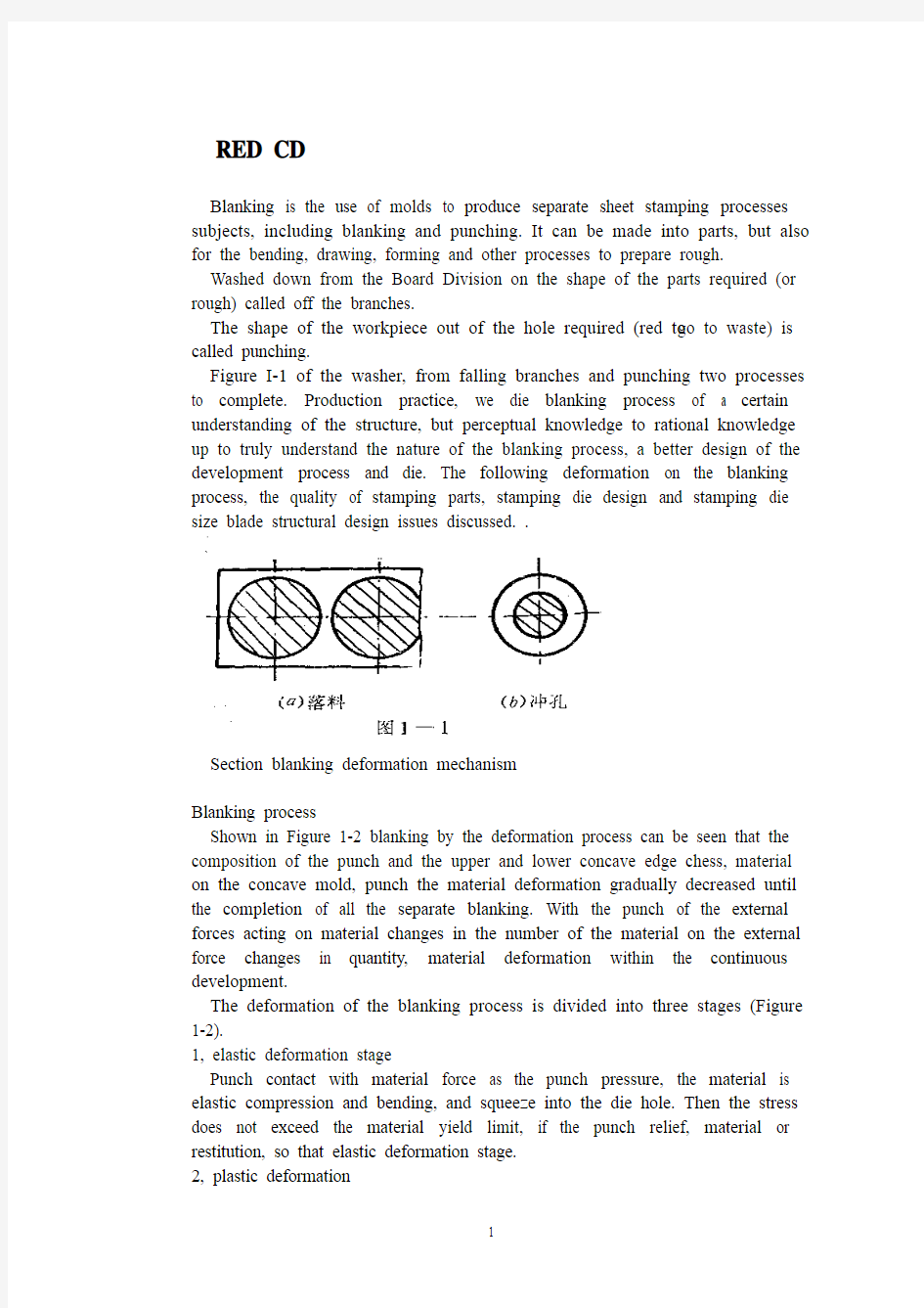
Figure I-1 of the washer, from falling branches and punching two processes to complete. Production practice, we die blanking process of a certain understanding of the structure, but perceptual knowledge to rational knowledge up to truly understand the nature of the blanking process, a better design of the development process and die. The following deformation on the blanking process, the quality of stamping parts, stamping die design and stamping die size blade structural design issues discussed. .
Section blanking deformation mechanism
Blanking process
Shown in Figure 1-2 blanking by the deformation process can be seen that the composition of the punch and the upper and lower concave edge chess, material on the concave mold, punch the material deformation gradually decreased until the completion of all the separate blanking. With the punch of the external forces acting on material changes in the number of the material on the external force changes in quantity, material deformation within the continuous development.
The deformation of the blanking process is divided into three stages (Figure 1-2).
1, elastic deformation stage
Punch contact with material force as the punch pressure, the material is elastic compression and bending, and squeeze into the die hole. Then the stress does not exceed the material yield limit, if the punch relief, material or restitution, so that elastic deformation stage.
2, plastic deformation
Punch to pressure, the stress reaches the yield limit of material, some metal is squeezed into the die hole, producing plastic shear deformation, are shining maggot cut surface. For convex, concave feel there is room between the depression, it is the plastic shear deformation is also accompanied by the bending and stretching.
3, fault isolation stage
Materials continue to increase external and internal stress increasing, convex, because the incision die stress concentration, shear strength over the first internal stress, micro-crack appears. Mold continuing under pressure, convex, concave mold cavities of the micro-crack edge to the material constantly within the share capital, then pulled off material separation. Such as convex, concave die gap was reasonable, the upper and lower crack coincide with each other. ' Stress and strain
Further analysis of blanking time of stress and strain state of deformation zone and help to the understanding of the blanking process. Die and punch in the edge of the joint line to take 'cell body, "whose stress-strain diagram shown in Figure 1-3. Can be seen from the figure, it seems
Metal fracture line AB that is cutting edge on-line) at 45 degrees. The main uranium direction I was pulling stress and tensile deformation, tensile stress the gold
Is a fiber elongation; its vertical axis 2 is the compression stress direction and compressive deformation, the fiber extrusion pressure; in the tangential direction of the stress and strain is very small, negligible; and principal stress direction at 45. Direction to the direction of maximum shear stress between the punch and die clearance, elongation and tear off the metal, resulting in broken fracture surface roughness, and with a burr.
The process can also blanking blanking force deformation curves of the figure is confirmed. Figure 2-9 (materials), is punching a 3 mm thick material punching power and punch of the curve. Can be seen from the diagram:
In the process of blanking blanking force size is constantly changing. AB section of the equivalent of punching the elastic deformation stage, BC Section for the plastic deformation stage. When the material internal stress to shear strength began to crack when the material, CD segment for the crack propagation until the material isolated rupture in order teams, DE Dan launch materials introduced die mouth piece.
Cut section of
See Figure 2-10
The deformation process of blanking the red plant parts are not smooth vertical section, the section has three areas, namely, with rounded corners, bright band and the fault zone.
Rounded band is in the process of blanking the beginning of plastic deformation. Since the bending and stretching metal fibers formed, soft material than hard Branch rounded large.
Light zone is the second phase of deformation produced plastic shear deformation of metal forming, has a smooth vertical surface, bright band of the entire cross section of 1 / 2 to 1 / 3 of the light bandwidth of soft materials, hard materials with a narrow bright . With the mechanical properties of materials, space, mold structural changes.
Fault is equivalent to the third stage of the blanking process, mainly due to the role of tensile stress, the continuous expansion of China cracks down payments second fiber extension, so a very rough surface is not smooth, and there Liaoduo. In the section on the same punch with these characteristics, but the distribution of the three regions opposite position and blanking.
Blanking addition to drag a section of rough dimensions, there are points dome curved, not flat, face a burr, so blanking requirements apply only to an Blanking.
Section Drawing gap
Blanking time requires not only the shape of call times out of line drawing parts, there should be a certain quality requirements, quality of stamping pieces is cut surface quality, dimensional accuracy and form error. Cut surface should be flat, smooth, no crack and tear, mezzanine and other defects, glitches small parts, the surface should be flat as possible, that is a small vaulted arch, size, degree of precision required to ensure the drawings do not exceed the tolerance range.
Factors that affect the quality of stamping pieces range from the actual production that, convex, concave die gap size and power uniformity, pattern edge state, the mold structure and manufacturing precision, quality materials, and so on all affect Na blanking. However, we must find out which plays a decisive role in the quality of the blanking factor. Gap is a.
Section 1 on the quality of blanking
Comparison of straight, smooth, and no burr. In this case, the quality of parts that is a good cross section.
When the gap is too hours of up and down the crack does not coincide with each other. . . .
When the gap is too large cracks do not overlap. . . . (See 2-11)
If the gap uneven distribution of local spikes. . . Uneven wear, increased, so clearance is not only to use reasonable and die on the manufacture and adjustment of space even when the guarantee.
2. Gap on the Dimensional Accuracy
Blanking Stamping dimensional accuracy refers to the actual size and nominal size of the margin, the difference is smaller the higher the precision.
difference between living in two areas packet error, one blanking punch or die with the size of the deviation, one mold itself create bias.
Blanking and convex, die size deviation was mainly due to:
Workpiece (waste) from the concave mold release, as caused by elastic recovery. Deviation may be positive, it could be negative.
Factors affecting the value of this deviation are:
1, convex, concave mold gap. Big gap. . . Tensile obvious effect, elastic recovery materials and parts to drop less than the die size, punching pieces. . Small gap. . .
2, material properties. Material properties and dimensional accuracy of packages since it will then determine the material properties of its material form in the amount of blanking. Outline of the elastic deformation of the soft small amount of elastic recovery after blanking also small, so the workpiece accuracy. Hard steel elastic recovery greater precision on the lower parts.
3, workpiece shape and size. Workpiece thickness and shape of post degree only-J also have an impact, thin elastic recovery of material punching shield large,-t pieces of low accuracy. The more complex the shape of the workpiece, die and create and adjust the gap when the more difficult to ensure uniform, so the greater the size of deviations.
See Figure 2-13
4. Blade-like quality video straight to the section noon
5. Gap on the impact of blanking force
The smaller the gap, blanking deformation area of the higher hydrostatic pressure, the greater the material change Kang force. Blanking force, the greater the contrary, when the gap increases, lower resistance, blanking force also
decreases, but the value is not reduced (see Figure 2-14)
Life on the sidelines of the impact of mold (see materials abbreviated talk)
Section III to determine clearance punch and die
Thus, convex and concave clearance on blanking die quality morning, punching power, tool life has a great impact, so the mold design - will select a reasonable gap to ensure Blanking section of good quality punching required is small, high-die life. But the difference of quality, precision, blanking force requirements in many aspects of cooperation were identified gap is not limited to the same - a value, but close to each other, taking into account the deviation
of model county manufacturing and use of wear and tear,
Therefore, production is often to select an appropriate range of reasonable space, as long as the gap falls within this range can be out of good parts, the scope of the minimum value, said minimum clearance Zmin reasonably small. Most reasonable position that the biggest gap Zmax. At least a reasonable gap Z Mi n can be with the board perpendicular to the section, without a significant glitch. In the largest gap Zmax "section can still be satisfied with the quality: just not with the board vertical. Taking into account the die wear and tear during use to increase the gap, so when the design and manufacture a new model to use the smallest reasonable space Zmin
Reasonable methods to determine gap calculated with the experience to determine and French.
One theory to define the law
Theory to define the main basis for the law is to ensure that cracks coincide in order to get a good cross section. Group 1 began the process of blanking the instantaneous crack q triangles from the graph we can find space z AB c
Type in: A, - convex molded into the depth; β - the maximum shear stress direction and the angle between the vertical;
Can be seen from the above formula, gap z and the material thickness t, the relative cut into the depth h. / T and the crack orientation day. Relevant, but to another with the material properties and β is related to the more rigid material, h. / T smaller. Therefore, we can see from the style, the main factors affecting the
value gap is the material properties and thickness. The more rigid material more thick, the necessary and reasonable value of the larger gap. Table 1-3 for the popular press materials, h. / T and β approximation.
A variety of materials h. / T and β value is still no accurate determination of value, and. Production is not convenient to use this method, so widely used empirical formula with the graph method.
Second, the experience to determine methods
Experience to determine the nature of law is based on the material and thickness, press-type to determine
The formula: K-factor related with the material properties. t - thickness of
material.
Soft materials such as 08, l0, brass, copper Z = (0.08-0.1) t
In hardwood Section: A3, A 4,20,25. Z = (0.1-0.I 2) t
Hard materials such as A5, 50 ... ... and so Z = (0.1-0.14) t
Lower limit of thin materials which take.
Third, the chart method
In addition, you can directly determine the space look-up table values (such as teaching materials 2-3,2-4,2-5 table) Table 2-5 is the former Ministry of Machinery Industry, "blanking clearance," Technical Guidance Document (JB/z271-86 ) recommended clearance value.
Over the past China's general information on using Soviet gap value, from the use of the experience, the gap value is generally small. One reason for this is the classification space is not used according to the characteristics of production, the other is only as the main basis for precision stamping parts, without considering the King and the chess section with a life of quality and other important factors, so many problems exist in production. For example: Wear + blanking force. . .
Therefore, in practice, in addition to special requirements of the workpiece outside the vertical section, as far as possible large gap.
In addition, my experience in practice should:
(1) z-punching to take the value of bigger than expected drop.
(2) red holes get bigger when the z value, to prevent broken punch.
(3) Carbide Die z value should be 30% larger than the steel.
(4)J die orifice is cone-shaped than straight smaller z value.
(5) high-speed stamping dies easily when the heat, f value should get bigger.
(6) when the punch and die wall thin. To prevent cracking up, should be enlarged punching z.
IV Size Calculation of Cutting Edge
Die edge dimensions and tolerances directly affect the dimensional accuracy of Blanking, also is sufficient to guarantee a reasonable gap. Therefore, the correct calculation of the mold edge mold design dimensions and tolerances are small - the work of great importance.
Dimensions and tolerances in calculating the cutting edge should follow the following principles:
1. Taking into account the drop size depends on the materials and parts die size, while punching pieces depends on the size of the punch dimensions of the blanking die design should be to die as the base is difficult to stay in the punch on the gap; Design Punching model should be based on the punch as the base, orange on the gap left in the concave. (There is a taper section, and the big end blanking parts die size = size, empty pieces of red punch small end size = size)
2. Taking into account the wear and tear will foot a larger die, the punch size decreases, in order to ensure the life of mold, the basic blanking die size should be taken close to or equal to the minimum limit of size of the workpiece; Piercing Punch basic dimensions shall be taken as close to the or equal to the maximum limit of size of workpiece, using the smallest reasonable gap value.
3. Sampling edge of manufacturing tolerances, the workpiece should be to ensure the accuracy and timeliness based clearance requirements. At the same time easy to mold manufacturing tolerance is too large, then out of the parts may be disqualified, or one can guarantee a reasonable gap; too small. And to die is difficult to mold manufacturing costs.
Accuracy and precision blanking dies relationship table
Special Note: If the size of the workpiece is not marked tolerance. I T14 without tolerances according to class to deal with, and die according to I D 11 manufacturing (non-graphic parts). Or by I T 6-7 class manufacturing (for round parts).
Mold processing method according to the different calculation methods are
divided into two kinds of edge
1. Separate punch and die machining
Separate processing: refers to the punch and die are processed separately by the respective drawings, mold the size of the gap processed by guarantee. Therefore, to calculate and mark out the punch and die dimensions and tolerances. This method is suitable for round or shape of a simple piece.
(1) Blanking Die Blanking piece size based degree d, according to the above principles, first determine the small scale and then reduce the die size in order to ensure a reasonable punch clearance. Knife-edge part of the incidence graph of the size shown.
Edge blanking die size is calculated as follows:
(2) The punching die set punching size of d. (Standard tolerance) calculated according to the principles of the punch first determine the size. Further increasing the die size in order to ensure a reasonable minimum edge clearance associated with some of the dimensions in Figure 2-13 (b) below.
Red edge aperture size is calculated as follows:
Symbol meaning:
X-tolerance zone offset factor, the purpose is to avoid all bias limit most blanking size (other omitted)
Its value and accuracy of the workpiece.
Tolerance band offset coefficient of 2-7 x to be investigated, or obtained by the following relations
Workpiece accuracy of IT10 above: x = 1
Workpiece accuracy of IT11 ~ 13: x = 1.75
Fine piece head IT14: x = 0.5
In order to ensure a reasonable space, mold manufacturing tolerances must meet the following conditions
Convex, concave mold separate processing advantages are: convex, concave
mold with interchangeable, easy to mold batch processing.
Convex, concave mold separate processing disadvantage: in order to ensure a reasonable gap. Require higher levels of mold manufacturing tolerances, mold making more difficult.
(Based on the use of examples to explain -6,2-7 table)
2. Punch and die with the processing
For complex shapes or thin material workpiece. In order to facilitate mold, should be used with the process. This method is first processed basis documents (when blanking die, punch when the punch), and then base the actual size of the Huai items to do with the other documents (when blanking punch, punch when punch), and then base the actual size of the Huai items to do with the other documents (when blanking punch, punch die when), in another space on the revised smallest reasonable value. Therefore, when used with the process, simply reference documents marked size and tolerance, another mark only basic dimensions. And marked "punch-foot small scale only by the actual preparation of the die to ensure the single gap" (blanking time); or "die size of the actual size of the preparation by the punch to ensure the side gap.." (When punching ). With the process, the base parts of the manufacturing tolerance 6f (or long) is no longer limited by the gap value, or even appropriate to enlarge manufacturing tolerances, so relatively easy to manufacture molds. Most factories have recently used this combined approach. Benchmark parts manufacturing tolerances generally preferable to A / 4
For some the shape of complex stamping parts. For each part of the size of the different nature of the wear law is different, it must be a specific analysis. Calculated separately.
Figure 2-20a for the blanking parts and die size ,2-20b for the punching pieces and punch size, in these two diagrams: A class size is worn larger size, such size should be charged formula feed die size (2 ? 2) calculation, B Class size is worn by people of such small size scale should be punching punch size formula (2-4) calculation; C Class size is worn the same size, of such size, the size of the workpiece in the middle of the basic dimensions as the mold, and then standard deviation can be symmetrical, the specific formula as follows:
V blanking force
Cutting edge technology, including separation of materials needed for
punching power and discharge power, pushing pieces of power and top pieces of power. After blanking. Washed down the workpiece (or waste) as elastic recovery and expansion will be within the infarct in the die hole. Similarly, the scrap piece〕〔or out of the hole on the elastic contraction because of tight coupling on the punch. ? Called the discharge power;? Named top material (pieces) force;? Called push material (pieces of) force.
The purpose of calculating power stamping process is it?
Reasonable choice is to press tonnage. (Of course choose not to consider the tonnage presses, as well as tables, press structure... Shut height, etc.) Select press when you press and public pressure (N) must make a big or equal to the total pressure during blanking
First, the calculation of punching force
Flat blade used in production Die Blanking, the blanking force can be calculated as follows;
K-safety factor, and generally the skin = 1.3. It takes into account mold edge wear and blunting the punch and the die gap is uneven material thickness deviation of the performance factors, such as Ko.
Blanking of high strength material or thick material and large size parts, the need to force a larger punch. If the blanking press more than the tonnage of the existing plant, it is necessary to reduce the blanking force.
1. Heating blanking
Material shear strength in the heated state decreased significantly, which can reduce the blanking force. However, heating the material will produce oxide, will be deformation, therefore applied only to thick or the surface quality and precision of less demanding jobs. Lower τ
2. Ladder arrangement blanking punch
In the multi-blanking punch in the punch made of different degrees south, a ladder Boubou set (Figure 2-18), will enable each punch the maximum blanking force of wood come together. Thereby reducing the total blanking force. Punch height difference between the thickness determined by: t <3mm, h = tt> 3mm h = 0.5t
When the punch by step layout 'symmetrically as possible. At the same time should do a small punch shorter, longer doing big punch, so to avoid a small punch side material flow because the pressure caused by tilt or break situation.
3. Oblique incision Die Blanking Figure 2-u-shaped cloth ladder A model aimed Knife-edge blanking level, the entire flat edge on the contact sheet to the rather oblique knife edge blanking die, because edge is inclined, not simultaneously cut into the knife-edge blanking time, but gradually punching material, so very dry by punching a small section of the post. Thus lower. Second, the calculation of other blanking force
Many factors affect these forces, mainly the mechanical properties and thickness, die gap, the workpiece shape and size and lubrication conditions. The effects of these factors is very complex to quantify accurately reflect the size of these forces is difficult. Therefore, the general experience with the following formula:
Fx = KF (K look-up table 2-10)
The overall strength based on the actual die stamping process concrete analysis of the structure.
外文资料译文
冲裁
冲裁是利用模具使板科产生分离的冲压工序,包括落料与冲孔。它可以制成零件,也可为弯曲、拉延、成形等工序准备毛坯。
从板科上冲下所需形状的零件(或毛坯)叫落科。
在工件上冲出所需形状的孔(冲去的为废料)叫冲孔。
如图I一1的垫圈,即由落科与冲孔两道工序完成。通过生产实践,我们对冲裁工序及其模具结构有了一定的了解,但感性认识上升到理性认识,才能真正了解冲裁过程的本质,更好地制定工艺和设计模具。下面就冲裁变形过程、冲裁件质量、冲裁模刀口尺寸设计及冲裁模结构设计等问
题进行分析讨论。 .
第一节冲裁变形机理
冲裁过程
由图1—2所示的冲裁变形过程可以看出,凸模与凹棋组成上下刃口,材料放在凹模上,凸模逐步下降使材料产生变形,直至全部分离完成冲裁。随着凸模作用在材料上的外力在数量上的变化,材料上的外力在数量上的变化,材料内部的变形不断发展。
整个冲裁过程的变形分为三个阶段(图1—2)。
1、弹性变形阶段
凸模接触材队由于凸模加压,材料发生弹性压缩与弯曲并挤入凹模洞口。这时材料内应力没有超过屈服极限,若凸模卸压,材料即恢复原状,故称弹性变形阶段。
2、塑性变形阶段
凸模继续加压,材料内应力达到屈服极限,部份金属被挤入凹模洞口,产生塑剪变形,得到光亮的蛆切断面。因凸、凹摸间存在间陷,故在塑剪变形的同时还伴有材料的弯曲与拉伸。
3、断裂分离阶段
外力继续增加材料内应力不断增大,在凸、凹模刀口处由于应力集中,内应力首先越过抗剪强度,出现微裂。模继续下压,凸、凹模刃凹处的微裂不断向材料内部扩股,材料随即被拉断分离。如凸、凹模间隙合理时,上下裂纹互相重合。
应力应变状态
进一步分析冲裁时变形区的应力应变状态,有助予对冲裁过程的了解。在凹模和凸模刃口的联线上取’单元体“,其应力应变图如图1—3所示。从图中可看出,似
金属断裂线AB即刃口联线)成45度。的主铀方向I是拉应力与拉伸变形,拉应力使金属纤维伸长;
与其垂直的主轴方向2是压应力与压缩变形,使纤维受压挤;在切线方向的应力与应变很小,略去不计;与主应力方向成45。方向为最大剪应力方向而凸凹模之间存在间隙,使金属伸长并撕断,致使破断裂面粗糙,并带有毛刺。
上述冲裁变形过程还可通过冲裁力的变化曲线图中得到确认。图2-9(教材),是冲裁厚为3毫米的材料时冲裁力与凸模行程的关系曲线。从图中可看出:
在冲裁过程中冲裁力的大小是不断变化的。AB段相当于冲裁的弹性变形阶段,BC段为塑性变形阶段。当材料内应力达到抗剪强度时材料开始产生裂纹,CD段为裂纹扩展直至材料分离的断型阶队,DE段位推出材料件推出凹模口。
剪切断面分析参见2-10图
上述冲裁变形过程得到的冲栽件断面并不是光滑垂直的,断面存在三个区域,即圆角带、光亮带与断裂带。
圆角带是在冲裁过程中塑性变形开始时.由于金属纤维的弯曲与拉伸而形成的,软料比硬科的圆角大。
光亮带是在变形过程的第二阶段金属产生塑剪变形时形成,有光滑垂直的表面,光亮带占全断面的1/2~1/3,软材料的光亮带宽,硬材料的光亮带窄。随材料机械性能,间隙,模具结构变化。
断裂带相当于冲裁过程的第三阶段,主要是由于拉应力的作用,裂纹不断扩民金届纤维断扩展,故表面极糙不光滑,且有料度。在冲孔的断面上同样具有上述特征,只是三个区域的分布位置与落料相反。
冲裁件除断面粗拖有维度外,还有点穹弯、不平整,端面有毛刺,所以冲裁只适用于一股要求的冲裁件。
第二节模具间隙
冲裁时不仅要求次冲出符合图纸形状叫零件,还应有一定质量要求,冲裁件质量是指切断面质量、尺寸精度及形状误差。切断面应平直,光洁、无裂纹和撕裂、夹层等缺陷、毛刺小零件,表面应尽可能平坦,即穹弓小,尺寸精度度保证不超出图纸规定的公差范围。
影响冲裁件质量的因素很多,从生产实际知道,凸、凹模间隙大小及力的均匀性、模具刃口状态、模具结构与制造精度、材料品质等,对冲裁件都有影呐。但我们必须从其中找出对冲裁质量起着决定性作用的因素。间隙就是一个。
1对冲裁断面质量的影响
比较平直、光洁,且无毛刺。在这种情况下零件断面质量认为是良好的。
当间隙过小时,则上下裂纹互不重合。
当间隙过大时,裂纹也不重合。(参见2-11)
若间隙分布不均,局部毛刺,磨损不均,加剧,所以间隙不仅要选用
合理,而且在制造和调整冲模时保证间隙均匀。
2.间隙对尺寸精度的影响
冲裁件的尺寸精度指冲件的实际尺寸与公称尺寸的差值,差值越小则精度越高。这个差值包活两方面的偏差,一是冲裁件与凸模或凹模尺寸的偏差,一是模具本身的制造偏差。
冲裁件与凸、凹模尺寸的偏差主要是由于:
制件(废料)从凹模内推出,由于材料的弹性恢复造成的。偏差值可能是正,也可能是负的。
影响这个偏差值的因素有:
1、凸、凹模间隙间隙大,拉伸作用明显,弹性恢复使落料件小于凹模尺寸,冲孔件间隙小。
2、材料性质材料性质对尺寸精度包有影响,因为材料性质其接决定了材料在冲裁形量。软纲的弹性变形量较小,冲裁后的弹性恢复量也就小,故工件精度较高。硬钢弹性恢复较大,工件精度就较低。
3、工件形状与尺寸。材料厚度与工件形状对只—J哨度也有影响,薄材料冲裁盾的弹性恢复大,—t件精度低。工件形状越复杂,模具创造及调整时就越难保证间隙匀,故尺寸偏差也越大。
参见图2-13
4.刃口状恋对断面质量的影晌
5.间隙对冲裁力的影响
间隙愈小,冲裁变形区的静水压力愈高,材料的变亢力愈大.冲裁力也就愈大,反之,当间隙增大时抗力降低,冲裁力也就减小,但减小的数值不大。(见图2-14)
间隙对对模具寿命的影响(见教材略讲)
第三节凸凹模间隙的确定
由此可见,凸、凹模间隙对冲裁件质晨、冲裁力、模具寿命都有很大的影响,因此设计模具时—定选择个合理的间隙,以保证冲裁件的断面质量好、所需冲裁小、模具寿命高。但是分别从质量、精度、冲裁力多方面的要求分别确定的合限间隙并不是同—个数值,而是彼此接近,同时考虑到模县制造中的偏差及使用中的磨损,故生产中常是选择一个适当的范围为合理间隙,只要间隙落在这个范围内就可以冲出良好制件,这个范围的最小值称最小合理间隙Zmin小.最大位称最大合理间隙Zmax。在最小合理隙Z Mi n时可以得到与板面垂直的断面,而不产生显著的毛刺。在最大间隙Zmax”仍能得到满意断面质量:只是个与板面不垂直。考虑到模具在使用过程中的磨损使间隙增大,故设计与制造新模时要采用最小合理间隙Zmin。
确定合理间隙的方法有理论计算与经验确定法两种。
一、理论确定法
理论确定法的主要依据是要保证裂纹重合,以便获得良好的断面。团1冲裁过程中开始产生裂纹的瞬时状态q从图中的三角形AB c可求得间隙z
式中:A,——凸模压入深度;β——最大剪应力方向与垂线间夹角;
从上式可看出,间隙z与材料厚度t、相对切入深度h。/t以及裂纹方向日。有关,而以与β又与材料性质有关,材料愈硬,h。/t愈小。因
此从上式可看出,影响间隙值的主要因素是材料性质和厚度。材料愈硬愈厚,所需合理间隙值愈大。表1—3为常用冲压材料的h。/t与β的近似值。
由于各种材料的h。/t与β值目前还没有准确的测定数值,而且.生产中使用这种法也不方便,故广泛采用经验公式与图表法。
二、经验确定法
经验确定法也是根据材料性质与厚度,按下式确定
式中: K—与材料性质有关的系数。
t——材料厚度。
软材料如08,l0,黄铜,紫铜Z=(0.08—0.1)t
中硬材科:A3,A 4,20,25.Z=(0.1—0.I 2)t
硬材如A5,50……等Z=(0.1-0.14)t
其中薄料取下限。
三、图表法
此外也可以直接查表确定间隙值(如教材2-3,2-4,2-5表)表2—5是原机械工业部的《冲裁间隙》指导性技术文件(JB/z271-86)推荐的间隙值。
过去我国一般采用苏联资料介绍的间隙值,从使用的经验来看,其间隙值一般较小。原因之一是这种间隙没有根据生产特点分类选用,其二是只以冲裁件精度作为主要依据,而没有考虑断面质景及棋具寿命等其他重要因素,所以在生产中存在不少问题。例如:磨损+冲裁力。。。
所以,在实际应用中,除了特别要求断面垂直的制件以外,尽量采用大间隙。
另外,实践中根据我的经验,还应:
(1)冲孔的z值可比落料取大些。
(2)冲小孔时z值取大些,以防凸模折断。
(3)硬质合金模z值应比钢模大30%。
(4)J凹模孔口为锥形的比直形的z值小些。
(5)高速冲压时模具易发热,f值应取大些。
(6)凸凹模壁薄时.为防止涨裂,应放大冲孔的z。
第四节冲裁模刃口尺寸的计算
模具的刃口尺寸和公差,直接影响到冲裁件的尺寸精度,合理间隙也要靠它来保证。因此,正确地计算模具的刃口尺寸和公差是模具设计小的—项十分重要的工作。
在计算刃口尺寸和公差时应遵循以下原则:
1.考虑到落料件的尺寸取决于凹模尺寸,而冲孔件的尺寸取决于凸模尺寸,故设计落料模时,应以凹模为基难,间隙留在凸模上;设计冲孔模时,应以凸模为基准,间隙留在凹橙上。(断面是有锥度的,落料件大端尺寸=凹模尺寸,冲空件小端尺寸=凸模尺寸)
2.考虑到磨损会使凹模尺个增大、凸模尺寸减小,为保证模具的寿命,落料凹模的基本尺寸应取靠近或等于工件的最小极限尺寸;冲孔凸模的基本尺寸应取靠近或等于工件的最大极限尺寸,并采用最小合理间隙值。
3.选样刃口的制造公差时,应保证工件的精度和合型间隙的要求.同时要便于模具制造公差过大,则冲出的件可能不合格,或个能保证合理间隙;过小.则模具制造难并使模具成本增加。
模具精度与冲裁件精度的关系见表
特别说明:若工件尺寸没有标注公差。则按未注公差I T14级来处理,而模具则按I丁11级制造(对非图形件).或按I T 6—7级制造(对圆形件)。
按模具加工方法的不同,刃口计算方法分为两种
1.凸模与凹模分开加工
分开加工:是指凸模与凹模分别按各自的图纸单独加工,模具间隙靠加工出的尺寸保证。因此,要分别计算和标注出凸模、凹模的尺寸和公差。此法适用于圆形或形状简单的工件。
(1)落料模设落料件尺寸度d,根据上述原则,先确定凹模尺小再减
小凸模尺寸以保证合理间隙。刀口部分各尺寸关联图如图所示。
(2)落料模的刃口尺寸计算公式如下
:
(2)冲孔模设冲孔尺寸为d。(标公差)根据上述计算原则先确定凸模尺寸。再增大凹模尺寸以保证最小合理间隙刃口部分各尺寸关联图如图2—13(b)所示。
冲孔径的刃口尺寸计算公式如下:
符号意义:
x-公差带偏移系数,目的是为避免多数冲裁件都偏向极限尺寸(其他略) 其值与工件精度有关。
公差带偏移系数x可查2—7,或按下列关系取
工件精度IT10以上:x=1
工件精度IT11~13: x=1.75
工件精目IT14:x=0.5
为了保证合理间隙,模具制造公差必须满足下列条件
凸、凹模分开加工的优点是:凸、凹模具有互换性,便于模具成批加工。
凸、凹模分开加工的缺点是:为了保证合理间隙.需要较高的模具制造公差等级,模具制造比较困难。
(根据例题讲解-6,2-7表的运用)
2.凸模与凹模配合加工
对于形状复杂或薄材料工件.为了便于模具制造,应采用配合加工。此方法是先加工基准件(落料时为凹模,冲孔时为凸模),然后根据基淮件的实际尺寸,来配做另一件(落料时为凸模、冲孔时为凸模),然后根据基淮件的实际尺寸,来配做另一件(落料时为凸模、冲孔时为凹模),在另一件上修出最小合理间隙值。故采用配合加工时,只需在基准件上标注尺寸和公差,另一件只标注基本尺寸.并注明“凸模尺小按凹模实际尺才配制,
保证单面间隙”(落料时);或“凹模尺寸按凸模实际尺寸配制,保证单面间隙。。”(冲孔时)。
配合加工时,基准件的制造公差6f(或久)不再受间隙值的限制,甚至可以适当放大制造公差,故模具比较容易制造。日前一般工厂都采用这种加上方法。基准件的制造公差一般可取A/4
对于一些形状复杂的冲裁件.出于各部分尺寸性质不同,其磨损规律也不同,故必须具体分析.分别计算。
如图2-20a为落料件和凹模尺寸,2—20b为冲孔件和凸模尺寸,在这两个图中:A类尺寸为磨损后变大的尺寸,这类尺寸应按落料凹模尺寸公式(2?2)计算,B类尺寸是磨损后受小的尺人这类尺寸应按冲孔凸模尺寸公式(2—4)计算;C类尺寸为磨损后不变的尺寸,对这类尺寸,把工件的中间尺寸作为模具的基本尺寸,然后标对称偏差即可,具体计算公式见下表:
第五节冲裁工艺力
冲裁工艺力包括分离材料所需的冲裁力以及卸料力、推件力和顶件力。冲裁后.冲下的工件(或废料)由于弹性恢复而扩张、会梗塞在凹模洞口内。同样、废料〔或工件〕上冲出的孔会因弹性收缩而箍紧在凸模上。?叫卸料力;?叫顶料(件)力;?叫推料(件)力。
计算冲压工艺力的目的是什么呢?
就是为合理选择压力机的吨位。(当然选择压力机不仅要考虑吨位,还有工作台,压机结构。。。闭合高度等)选择压力机时,压力机的公你压力(N)必须大干或等于冲裁时的总压力
一、冲裁力的计算
生产中常用平刀口模具冲裁,其冲裁力可按下式计算;
K -安全系数,一般取皮=1.3。它考虑到模具刃口磨损变钝、凸模与凹模间隙不均匀、材料性能柯厚度偏差波动等因素。
冲裁高强度材料或厚料和大尺寸工件时,需要的冲裁力较大。如果冲
模具毕业设计外文翻译(英文+译文)
Injection Molding The basic concept of injection molding revolves around the ability of a thermoplastic material to be softened by heat and to harden when cooled .In most operations ,granular material (the plastic resin) is fed into one end of the cylinder (usually through a feeding device known as a hopper ),heated, and softened(plasticized or plasticized),forced out the other end of the cylinder, while it is still in the form of a melt, through a nozzle into a relatively cool mold held closed under pressure.Here,the melt cools and hardens until fully set-up. The mold is then opened, the piece ejected, and the sequence repeated. Thus, the significant elements of an injection molding machine become: 1) the way in which the melt is plasticized (softened) and forced into the mold (called the injection unit); 2) the system for opening the mold and closing it under pressure (called the clamping unit);3) the type of mold used;4) the machine controls. The part of an injection-molding machine, which converts a plastic material from a sold phase to homogeneous seni-liguid phase by raising its temperature .This unit maintains the material at a present temperature and force it through the injection unit nozzle into a mold .The plunger is a combination of the injection and plasticizing device in which a heating chamber is mounted between the plunger and mold. This chamber heats the plastic material by conduction .The plunger, on each stroke; pushes unbelted plastic material into the chamber, which in turn forces plastic melt at the front of the chamber out through the nozzle The part of an injection molding machine in which the mold is mounted, and which provides the motion and force to open and close the mold and to hold the mold close with force during injection .This unit can also provide other features necessary for the effective functioning of the molding operation .Moving
概率论毕业论文外文翻译
Statistical hypothesis testing Adriana Albu,Loredana Ungureanu Politehnica University Timisoara,adrianaa@aut.utt.ro Politehnica University Timisoara,loredanau@aut.utt.ro Abstract In this article,we present a Bayesian statistical hypothesis testing inspection, testing theory and the process Mentioned hypothesis testing in the real world and the importance of, and successful test of the Notes. Key words Bayesian hypothesis testing; Bayesian inference;Test of significance Introduction A statistical hypothesis test is a method of making decisions using data, whether from a controlled experiment or an observational study (not controlled). In statistics, a result is called statistically significant if it is unlikely to have occurred by chance alone, according to a pre-determined threshold probability, the significance level. The phrase "test of significance" was coined by Ronald Fisher: "Critical tests of this kind may be called tests of significance, and when such tests are available we may discover whether a second sample is or is not significantly different from the first."[1] Hypothesis testing is sometimes called confirmatory data analysis, in contrast to exploratory data analysis. In frequency probability,these decisions are almost always made using null-hypothesis tests. These are tests that answer the question Assuming that the null hypothesis is true, what is the probability of observing a value for the test statistic that is at [] least as extreme as the value that was actually observed?) 2 More formally, they represent answers to the question, posed before undertaking an experiment,of what outcomes of the experiment would lead to rejection of the null hypothesis for a pre-specified probability of an incorrect rejection. One use of hypothesis testing is deciding whether experimental results contain enough information to cast doubt on conventional wisdom. Statistical hypothesis testing is a key technique of frequentist statistical inference. The Bayesian approach to hypothesis testing is to base rejection of the hypothesis on the posterior probability.[3][4]Other approaches to reaching a decision based on data are available via decision theory and optimal decisions. The critical region of a hypothesis test is the set of all outcomes which cause the null hypothesis to be rejected in favor of the alternative hypothesis. The critical region is usually denoted by the letter C. One-sample tests are appropriate when a sample is being compared to the population from a hypothesis. The population characteristics are known from theory or are calculated from the population.
毕业设计外文翻译资料
外文出处: 《Exploiting Software How to Break Code》By Greg Hoglund, Gary McGraw Publisher : Addison Wesley Pub Date : February 17, 2004 ISBN : 0-201-78695-8 译文标题: JDBC接口技术 译文: JDBC是一种可用于执行SQL语句的JavaAPI(ApplicationProgrammingInterface应用程序设计接口)。它由一些Java语言编写的类和界面组成。JDBC为数据库应用开发人员、数据库前台工具开发人员提供了一种标准的应用程序设计接口,使开发人员可以用纯Java语言编写完整的数据库应用程序。 一、ODBC到JDBC的发展历程 说到JDBC,很容易让人联想到另一个十分熟悉的字眼“ODBC”。它们之间有没有联系呢?如果有,那么它们之间又是怎样的关系呢? ODBC是OpenDatabaseConnectivity的英文简写。它是一种用来在相关或不相关的数据库管理系统(DBMS)中存取数据的,用C语言实现的,标准应用程序数据接口。通过ODBCAPI,应用程序可以存取保存在多种不同数据库管理系统(DBMS)中的数据,而不论每个DBMS使用了何种数据存储格式和编程接口。 1.ODBC的结构模型 ODBC的结构包括四个主要部分:应用程序接口、驱动器管理器、数据库驱动器和数据源。应用程序接口:屏蔽不同的ODBC数据库驱动器之间函数调用的差别,为用户提供统一的SQL编程接口。 驱动器管理器:为应用程序装载数据库驱动器。 数据库驱动器:实现ODBC的函数调用,提供对特定数据源的SQL请求。如果需要,数据库驱动器将修改应用程序的请求,使得请求符合相关的DBMS所支持的文法。 数据源:由用户想要存取的数据以及与它相关的操作系统、DBMS和用于访问DBMS的网络平台组成。 虽然ODBC驱动器管理器的主要目的是加载数据库驱动器,以便ODBC函数调用,但是数据库驱动器本身也执行ODBC函数调用,并与数据库相互配合。因此当应用系统发出调用与数据源进行连接时,数据库驱动器能管理通信协议。当建立起与数据源的连接时,数据库驱动器便能处理应用系统向DBMS发出的请求,对分析或发自数据源的设计进行必要的翻译,并将结果返回给应用系统。 2.JDBC的诞生 自从Java语言于1995年5月正式公布以来,Java风靡全球。出现大量的用java语言编写的程序,其中也包括数据库应用程序。由于没有一个Java语言的API,编程人员不得不在Java程序中加入C语言的ODBC函数调用。这就使很多Java的优秀特性无法充分发挥,比如平台无关性、面向对象特性等。随着越来越多的编程人员对Java语言的日益喜爱,越来越多的公司在Java程序开发上投入的精力日益增加,对java语言接口的访问数据库的API 的要求越来越强烈。也由于ODBC的有其不足之处,比如它并不容易使用,没有面向对象的特性等等,SUN公司决定开发一Java语言为接口的数据库应用程序开发接口。在JDK1.x 版本中,JDBC只是一个可选部件,到了JDK1.1公布时,SQL类包(也就是JDBCAPI)
毕业论文外文翻译模版
吉林化工学院理学院 毕业论文外文翻译English Title(Times New Roman ,三号) 学生学号:08810219 学生姓名:袁庚文 专业班级:信息与计算科学0802 指导教师:赵瑛 职称副教授 起止日期:2012.2.27~2012.3.14 吉林化工学院 Jilin Institute of Chemical Technology
1 外文翻译的基本内容 应选择与本课题密切相关的外文文献(学术期刊网上的),译成中文,与原文装订在一起并独立成册。在毕业答辩前,同论文一起上交。译文字数不应少于3000个汉字。 2 书写规范 2.1 外文翻译的正文格式 正文版心设置为:上边距:3.5厘米,下边距:2.5厘米,左边距:3.5厘米,右边距:2厘米,页眉:2.5厘米,页脚:2厘米。 中文部分正文选用模板中的样式所定义的“正文”,每段落首行缩进2字;或者手动设置成每段落首行缩进2字,字体:宋体,字号:小四,行距:多倍行距1.3,间距:前段、后段均为0行。 这部分工作模板中已经自动设置为缺省值。 2.2标题格式 特别注意:各级标题的具体形式可参照外文原文确定。 1.第一级标题(如:第1章绪论)选用模板中的样式所定义的“标题1”,居左;或者手动设置成字体:黑体,居左,字号:三号,1.5倍行距,段后11磅,段前为11磅。 2.第二级标题(如:1.2 摘要与关键词)选用模板中的样式所定义的“标题2”,居左;或者手动设置成字体:黑体,居左,字号:四号,1.5倍行距,段后为0,段前0.5行。 3.第三级标题(如:1.2.1 摘要)选用模板中的样式所定义的“标题3”,居左;或者手动设置成字体:黑体,居左,字号:小四,1.5倍行距,段后为0,段前0.5行。 标题和后面文字之间空一格(半角)。 3 图表及公式等的格式说明 图表、公式、参考文献等的格式详见《吉林化工学院本科学生毕业设计说明书(论文)撰写规范及标准模版》中相关的说明。
机械毕业设计英文外文翻译588柱塞式液压缸、起重器和柱塞
附录A译文 (一) 柱塞式液压缸、起重器和柱塞 液压缸、起重器和柱塞的基本术语可以被看作为同义词。通常首先描述的是其基本质特征,“jack”通常用来描述,应用于起重器中的液压缸,而且在大多数应用驱动器的特定工业场合来提供起重装置,“ram”经常被应用于高输出力的大型、重型液压缸,其它一些权威书籍可能将“ram”定义为活塞和杆是相同直径的液压缸,尽管这种液压缸更准确的应该被叫做柱塞式油缸,或置换式液压缸,这些形式的液压缸单一作用式并有其相对的应用局限。 液压缸可为单作用式,在单作用液压缸情况下,运动由弹簧或某种外力或重力使活塞返回到起始位置时释放压力来完成,在这种情况下弹簧返回,再液压条件下可获得的输出力可以被弹簧抗力所减轻。 双作用液压缸再普通应用场合是最常用的,液流上被安装液压缸两端,被选择器交替实现输入口,输出口作用。最大的可获得的输出的仅比单作用液压缸所获得的输出稍小些,因为当液体压力被反向加压时组织泄露,因而增加了摩擦力抵抗运动。 在反向运动时,可获得的力会由于活塞和杆面积的不同而降低了活塞作用面积减少,反向压力也是存在的,这种性能损失也许会很小,但在实际中明显地减少理论性能,而且液压缸的理论性能是有一定规格的,允许的公称公差以适应摩擦损失。 大多数的液压缸是单杆式的,双杆式的液压缸可能被应用在要求特高刚度下。对于双作用式液压缸,冲压力在伸出和缩回是相等的,这里可以估计到相比在相同直径的液压缸由于杆的封闭作用,摩擦力也会两端的密封杆和密封轴承而增大。 液压缸被广泛用于工业液体系统中,这些液压缸也别称为线性原动机或往复原动机。通常液压缸由循环管,活塞和杆运动处两侧的密封组织,活塞杆可被设计在液压缸的一侧或两侧,围绕活塞杆向液压缸外的液体温度可以由正确设计的还有密封垫用途的应用。再这当中我们将学习各种类型的液压缸以及它们是如何应用的液压缸的用途会对工业水利学的学习有很大帮助。
毕业论文参考文献格式示例
例: 参考文献: [1]毛蕴诗. 跨国公司战略竞争与国际直接投资[M].广州: 中山大学出版社 [2]ALEXANDER N. International Retailing [M].Oxford:Blackwell Business,1997 .日本税法[M].战宪斌,郑林根,译.北京:法律出版社.信息技术与信息服务[M]//许厚泽,赵其国.信息技术与应用.,於方,蒋红强,等. 建立中国绿色GDP 核算体系:机遇、挑战与对策[C]//潘岳,绿色GDP 核算体系国际研讨会论文集. 北京:中国环境科学出版社, 2004:35-42. 黄祖洽.软凝聚态物理研究进展[J].北京师范大学学报:自然科学版,2005,41(1) :N, MYERS H. European Retail Expansion in South East Asia[J].European 1999,34(2): 45-50. 丁文祥.数字革命与竞争国际化[N]. 中国青年报, 2000-11-20 (15). 张志祥.间断动力系统的随机扰动及其在守恒律方程中的应用[D].北京:北京大学数学学院,1998. 冯西桥.核反应堆压力管 道与压力容器的LBB 分析[R].北京:清华大学核能技术设计研究院莫少强.数字式中文全文文献格式的设计与研究[J/OL].情报学报,1999,18(4):https://www.360docs.net/doc/7913392688.html,/periodical/qbxb/qbxb990407.htm. 奚纪荣,邱志方.武略文韬:军事知识趣谈[M/OL].上海: 汉语大词典出版社, 2001: [13]杜莲.“9·11”事件影响英国出版news/20010929/200109290016.htm. 英文作者姓名全部 用大写字母
模具毕业设计外文翻译7081204
(此文档为word格式,下载后您可任意编辑修改!) 冷冲模具使用寿命的影响及对策 冲压模具概述 冲压模具--在冷冲压加工中,将材料(金属或非金属)加工成零件(或半成品)的一种特殊工艺装备,称为冷冲压模具(俗称冷冲模)。冲压--是在室温下,利用安装在压力机上的模具对材料施加压力,使其产生分离或塑性变形,从而获得所需零件的一种压力加工方法。 冲压模具的形式很多,一般可按以下几个主要特征分类: 1?根据工艺性质分类 (1)冲裁模沿封闭或敞开的轮廓线使材料产生分离的模具。如落料模、冲孔模、切断模、切口模、切边模、剖切模等。 (2)弯曲模使板料毛坯或其他坯料沿着直线(弯曲线)产生弯曲变形,从而获得一定角度和形状的工件的模具。 (3)拉深模是把板料毛坯制成开口空心件,或使空心件进一步改变形状和尺寸的模具。 (4)成形模是将毛坯或半成品工件按图凸、凹模的形状直接复制成形,而材料本身仅产生局部塑性变形的模具。如胀形模、缩口模、扩口模、起伏成形模、翻边模、整形模等。2?根据工序组合程度分类 (1)单工序模在压力机的一次行程中,只完成一道冲压工序的模具。 (2)复合模只有一个工位,在压力机的一次行程中,在同一工位上同时完成两道或两道以上冲压工序的模具。 (3)级进模(也称连续模) 在毛坯的送进方向上,具有两个或更多的工位,在压力机的一次行程中,在不同的工位上逐次完成两道或两道以上冲压工序的模具。 冲冷冲模全称为冷冲压模具。 冷冲压模具是一种应用于模具行业冷冲压模具及其配件所需高性能结构陶瓷材料的制备方法,高性能陶瓷模具及其配件材料由氧化锆、氧化钇粉中加铝、错元素构成,制备工艺是将氧化锆溶液、氧化钇溶液、氧化错溶液、氧化铝溶液按一定比例混合配成母液,滴入碳酸氢铵,采用共沉淀方法合成模具及其配件陶瓷材料所需的原材料,反应生成的沉淀经滤水、干燥,煅烧得到高性能陶瓷模具及其配件材料超微粉,再经过成型、烧结、精加工,便得到高性能陶瓷模具及其配件材料。本发明的优点是本发明制成的冷冲压模具及其配件使用寿命长,在冲压过程中未出现模具及其配件与冲压件产生粘结现象,冲压件表面光滑、无毛刺,完全可以替代传统高速钢、钨钢材料。 冷冲模具主要零件冷冲模具是冲压加工的主要工艺装备,冲压制件就是靠上、下模具的相对运动来完成的。 加工时由于上、下模具之间不断地分合,如果操作工人的手指不断进入或停留在模具闭合区,便会对其人身安全带来严重威胁。 1
毕业设计外文翻译附原文
外文翻译 专业机械设计制造及其自动化学生姓名刘链柱 班级机制111 学号1110101102 指导教师葛友华
外文资料名称: Design and performance evaluation of vacuum cleaners using cyclone technology 外文资料出处:Korean J. Chem. Eng., 23(6), (用外文写) 925-930 (2006) 附件: 1.外文资料翻译译文 2.外文原文
应用旋风技术真空吸尘器的设计和性能介绍 吉尔泰金,洪城铱昌,宰瑾李, 刘链柱译 摘要:旋风型分离器技术用于真空吸尘器 - 轴向进流旋风和切向进气道流旋风有效地收集粉尘和降低压力降已被实验研究。优化设计等因素作为集尘效率,压降,并切成尺寸被粒度对应于分级收集的50%的效率进行了研究。颗粒切成大小降低入口面积,体直径,减小涡取景器直径的旋风。切向入口的双流量气旋具有良好的性能考虑的350毫米汞柱的低压降和为1.5μm的质量中位直径在1米3的流量的截止尺寸。一使用切向入口的双流量旋风吸尘器示出了势是一种有效的方法,用于收集在家庭中产生的粉尘。 摘要及关键词:吸尘器; 粉尘; 旋风分离器 引言 我们这个时代的很大一部分都花在了房子,工作场所,或其他建筑,因此,室内空间应该是既舒适情绪和卫生。但室内空气中含有超过室外空气因气密性的二次污染物,毒物,食品气味。这是通过使用产生在建筑中的新材料和设备。真空吸尘器为代表的家电去除有害物质从地板到地毯所用的商用真空吸尘器房子由纸过滤,预过滤器和排气过滤器通过洁净的空气排放到大气中。虽然真空吸尘器是方便在使用中,吸入压力下降说唱空转成比例地清洗的时间,以及纸过滤器也应定期更换,由于压力下降,气味和细菌通过纸过滤器内的残留粉尘。 图1示出了大气气溶胶的粒度分布通常是双峰形,在粗颗粒(>2.0微米)模式为主要的外部来源,如风吹尘,海盐喷雾,火山,从工厂直接排放和车辆废气排放,以及那些在细颗粒模式包括燃烧或光化学反应。表1显示模式,典型的大气航空的直径和质量浓度溶胶被许多研究者测量。精细模式在0.18?0.36 在5.7到25微米尺寸范围微米尺寸范围。质量浓度为2?205微克,可直接在大气气溶胶和 3.85至36.3μg/m3柴油气溶胶。
大学毕业论文---软件专业外文文献中英文翻译
软件专业毕业论文外文文献中英文翻译 Object landscapes and lifetimes Tech nically, OOP is just about abstract data typing, in herita nee, and polymorphism, but other issues can be at least as importa nt. The rema in der of this sect ion will cover these issues. One of the most importa nt factors is the way objects are created and destroyed. Where is the data for an object and how is the lifetime of the object con trolled? There are differe nt philosophies at work here. C++ takes the approach that con trol of efficie ncy is the most importa nt issue, so it gives the programmer a choice. For maximum run-time speed, the storage and lifetime can be determined while the program is being written, by placing the objects on the stack (these are sometimes called automatic or scoped variables) or in the static storage area. This places a priority on the speed of storage allocatio n and release, and con trol of these can be very valuable in some situati ons. However, you sacrifice flexibility because you must know the exact qua ntity, lifetime, and type of objects while you're writing the program. If you are trying to solve a more general problem such as computer-aided desig n, warehouse man ageme nt, or air-traffic con trol, this is too restrictive. The sec ond approach is to create objects dyn amically in a pool of memory called the heap. In this approach, you don't know un til run-time how many objects you n eed, what their lifetime is, or what their exact type is. Those are determined at the spur of the moment while the program is runnin g. If you n eed a new object, you simply make it on the heap at the point that you n eed it. Because the storage is man aged dyn amically, at run-time, the amount of time required to allocate storage on the heap is sig ni fica ntly Ion ger tha n the time to create storage on the stack. (Creat ing storage on the stack is ofte n a si ngle assembly in structio n to move the stack poin ter dow n, and ano ther to move it back up.) The dyn amic approach makes the gen erally logical assumpti on that objects tend to be complicated, so the extra overhead of finding storage and releas ing that storage will not have an importa nt impact on the creati on of an object .In additi on, the greater flexibility is esse ntial to solve the gen eral program ming problem. Java uses the sec ond approach, exclusive". Every time you want to create an object, you use the new keyword to build a dyn amic in sta nee of that object. There's ano ther issue, however, and that's the lifetime of an object. With Ian guages that allow objects to be created on the stack, the compiler determines how long the object lasts and can automatically destroy it. However, if you create it on the heap the compiler has no kno wledge of its lifetime. In a Ianguage like C++, you must determine programmatically when to destroy the
模具专业外文文献最新
济南大学泉城学院 毕业设计外文资料翻译 题目现代快速经济制造模具技术 专业机械制造及其自动化 班级专升本1302班 学生刘计良 学号2013040156 指导教师刘彦 二〇一五年三月十六日
Int J Adv Manuf Technol ,(2011) 53:1–10DOI 10.1007/s00170-010-2796-y Modular design applied to beverage-container injection molds Ming-Shyan Huang & Ming-Kai Hsu Received: 16 March 2010 / Accepted: 15 June 2010 / Published online: 25 June 2010 # Springer-Verlag London Limited 2010 Modular design applied to beverage-container injection molds The Abstract: This work applies modular design concepts to designating beverage-container injection molds. This study aims to develop a method of controlling costs and time in relation to mold development, and also to improve product design. This investigation comprises two parts: functional-ity coding, and establishing a standard operation procedure, specifically designed for beverage-container injection mold design and manufacturing. First, the injection mold is divided into several modules, each with a specific function. Each module is further divided into several structural units possessing sub-function or sub-sub-function. Next, dimen-sions and specifications of each unit are standardized and a compatible interface is constructed linking relevant units. This work employs a cup-shaped beverage container to experimentally assess the performance of the modular design approach. The experimental results indicate that the modular design approach to manufacturing injection molds shortens development time by 36% and reduces costs by 19 23% compared with the conventional ap-proach. Meanwhile, the information on
毕业论文 外文翻译#(精选.)
毕业论文(设计)外文翻译 题目:中国上市公司偏好股权融资:非制度性因素 系部名称:经济管理系专业班级:会计082班 学生姓名:任民学号: 200880444228 指导教师:冯银波教师职称:讲师 年月日
译文: 中国上市公司偏好股权融资:非制度性因素 国际商业管理杂志 2009.10 摘要:本文把重点集中于中国上市公司的融资活动,运用西方融资理论,从非制度性因素方面,如融资成本、企业资产类型和质量、盈利能力、行业因素、股权结构因素、财务管理水平和社会文化,分析了中国上市公司倾向于股权融资的原因,并得出结论,股权融资偏好是上市公司根据中国融资环境的一种合理的选择。最后,针对公司的股权融资偏好提出了一些简明的建议。 关键词:股权融资,非制度性因素,融资成本 一、前言 中国上市公司偏好于股权融资,根据中国证券报的数据显示,1997年上市公司在资本市场的融资金额为95.87亿美元,其中股票融资的比例是72.5%,,在1998年和1999年比例分别为72.6%和72.3%,另一方面,债券融资的比例分别是17.8%,24.9%和25.1%。在这三年,股票融资的比例,在比中国发达的资本市场中却在下跌。以美国为例,当美国企业需要的资金在资本市场上,于股权融资相比他们宁愿选择债券融资。统计数据显示,从1970年到1985年,美日企业债券融资占了境外融资的91.7%,比股权融资高很多。阎达五等发现,大约中国3/4的上市公司偏好于股权融资。许多研究的学者认为,上市公司按以下顺序进行外部融资:第一个是股票基金,第二个是可转换债券,三是短期债务,最后一个是长期负债。许多研究人员通常分析我国上市公司偏好股权是由于我们国家的经济改革所带来的制度性因素。他们认为,上市公司的融资活动违背了西方古典融资理论只是因为那些制度性原因。例如,优序融资理论认为,当企业需要资金时,他们首先应该转向内部资金(折旧和留存收益),然后再进行债权融资,最后的选择是股票融资。在这篇文章中,笔者认为,这是因为具体的金融环境激活了企业的这种偏好,并结合了非制度性因素和西方金融理论,尝试解释股权融资偏好的原因。
毕业设计外文翻译
毕业设计(论文) 外文翻译 题目西安市水源工程中的 水电站设计 专业水利水电工程 班级 学生 指导教师 2016年
研究钢弧形闸门的动态稳定性 牛志国 河海大学水利水电工程学院,中国南京,邮编210098 nzg_197901@https://www.360docs.net/doc/7913392688.html,,niuzhiguo@https://www.360docs.net/doc/7913392688.html, 李同春 河海大学水利水电工程学院,中国南京,邮编210098 ltchhu@https://www.360docs.net/doc/7913392688.html, 摘要 由于钢弧形闸门的结构特征和弹力,调查对参数共振的弧形闸门的臂一直是研究领域的热点话题弧形弧形闸门的动力稳定性。在这个论文中,简化空间框架作为分析模型,根据弹性体薄壁结构的扰动方程和梁单元模型和薄壁结构的梁单元模型,动态不稳定区域的弧形闸门可以通过有限元的方法,应用有限元的方法计算动态不稳定性的主要区域的弧形弧形闸门工作。此外,结合物理和数值模型,对识别新方法的参数共振钢弧形闸门提出了调查,本文不仅是重要的改进弧形闸门的参数振动的计算方法,但也为进一步研究弧形弧形闸门结构的动态稳定性打下了坚实的基础。 简介 低举升力,没有门槽,好流型,和操作方便等优点,使钢弧形闸门已经广泛应用于水工建筑物。弧形闸门的结构特点是液压完全作用于弧形闸门,通过门叶和主大梁,所以弧形闸门臂是主要的组件确保弧形闸门安全操作。如果周期性轴向载荷作用于手臂,手臂的不稳定是在一定条件下可能发生。调查指出:在弧形闸门的20次事故中,除了极特殊的破坏情况下,弧形闸门的破坏的原因是弧形闸门臂的不稳定;此外,明显的动态作用下发生破坏。例如:张山闸,位于中国的江苏省,包括36个弧形闸门。当一个弧形闸门打开放水时,门被破坏了,而其他弧形闸门则关闭,受到静态静水压力仍然是一样的,很明显,一个动态的加载是造成的弧形闸门破坏一个主要因素。因此弧形闸门臂的动态不稳定是造成弧形闸门(特别是低水头的弧形闸门)破坏的主要原是毫无疑问。
电子信息工程专业毕业论文外文翻译中英文对照翻译
本科毕业设计(论文)中英文对照翻译 院(系部)电气工程与自动化 专业名称电子信息工程 年级班级 04级7班 学生姓名 指导老师
Infrared Remote Control System Abstract Red outside data correspondence the technique be currently within the scope of world drive extensive usage of a kind of wireless conjunction technique,drive numerous hardware and software platform support. Red outside the transceiver product have cost low, small scaled turn, the baud rate be quick, point to point SSL, be free from electromagnetism thousand Raos etc.characteristics, can realization information at dissimilarity of the product fast, convenience, safely exchange and transmission, at short distance wireless deliver aspect to own very obvious of advantage.Along with red outside the data deliver a technique more and more mature, the cost descend, red outside the transceiver necessarily will get at the short distance communication realm more extensive of application. The purpose that design this system is transmit cu stomer’s operation information with infrared rays for transmit media, then demodulate original signal with receive circuit. It use coding chip to modulate signal and use decoding chip to demodulate signal. The coding chip is PT2262 and decoding chip is PT2272. Both chips are made in Taiwan. Main work principle is that we provide to input the information for the PT2262 with coding keyboard. The input information was coded by PT2262 and loading to high frequent load wave whose frequent is 38 kHz, then modulate infrared transmit dioxide and radiate space outside when it attian enough power. The receive circuit receive the signal and demodulate original information. The original signal was decoded by PT2272, so as to drive some circuit to accomplish