外文翻译----步进电机基础
资料翻译
英文资料
Stepper Motor Basics
[TieluoLin.Jianxun Zhang.DSP-based microstep controller of stepper motor.Intelligent Control and Automation, 2004.Fifth World Congress on Volume 5, 15-19 June 2004.]
A stepper motor is an electromechanical device which converts electrical pulses into discrete mechanical movements. The shaft or spindle of a stepper motor rotates in discrete step increments when electrical command pulses are applied to it in the proper sequence. The motors rotation has several direct relationships to these applied input pulses. The sequence of the applied pulses is directly related to the direction of motor shafts rotation. The speed of the motor shafts rotation is directly related to the frequency of the input pulses and the length of rotation is directly related to the number of input pulses applied.
Stepper Motor Advantages and Disadvantages
Advantages
1. The rotation angle of the motor is proportional to the input pulse.
2. The motor has full torque at standstill (if the windings are energized)
3. Precise positioning and repeatability of movement since good stepper motors have an accuracy of 3 – 5% of a step and this error is non cumulative from one step to the next.
4. Excellent response to starting/stopping/reversing.
5. Very reliable since there are no contact brushes in the motor. Therefore the life of the motor is simply dependant on the life of the bearing.
6. The motors response to digital input pulses provides open-loop control, making the motor simpler and less costly to control.
7. It is possible to achieve very low speed synchronous rotation with a load that is directly coupled to the shaft.
8. A wide range of rotational speeds can be realized as the speed is proportional to the frequency of the input pulses.
Disadvantages
1. Resonances can occur if not properly controlled.
2. Not easy to operate at extremely high speeds.
Open Loop Operation
One of the most significant advantages of a stepper motor is its ability to be accurately controlled in an open loop system. Open loop control means no feedback information about position is needed. This type of control eliminates the need for expensive sensing and feedback devices such as optical encoders. Your position is known simply by keeping track of the input step pulses.
Stepper Motor Types
There are three basic stepper motor types. They are :
? Variable-reluctance
? Permanent-magnet
? Hybrid
Variable-reluctance (VR)
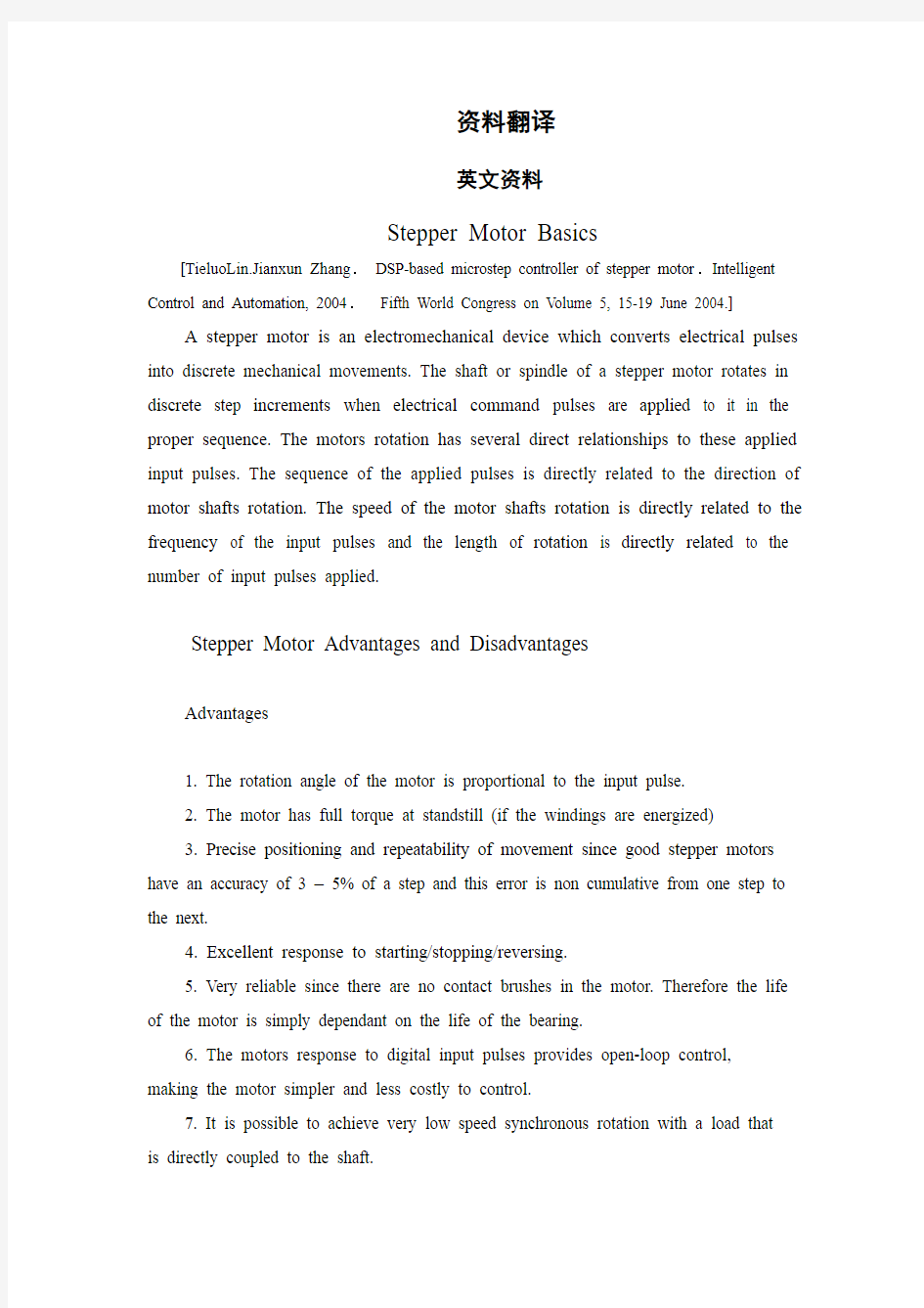
This type of stepper motor has been around for a long time. It is probably the easiest to understand from a structural point of view. Figure 1 shows a cross section of a typical V.R. stepper motor. This type of motor consists of a soft iron multi-toothed rotor and a wound stator. When the stator windings are energized with DC current the poles become magnetized. Rotation occurs when the rotor teeth are attracted to the energized stator poles.
Figure 1. Cross-section of a variablereluctance(VR) motor.
Permanent Magnet (PM)
Often referred to as a “tin can” or “canstock” motor the permanent magnet step motor is a low cost and low resolution type motor with typical step angles of 7.5° to 15°. (48 –24steps/revolution) PM motors as the name implies have permanent magnets added to the motor structure. The rotor no longer has teeth as with the VR motor. Instead the rotor is magnetized with alternating north and south poles situated in a straight line parallel to the rotor shaft. These magnetized rotor poles provide an increased magnetic flux intensity and because of this the PM motor exhibits improved torque characteristics when compared with the VR type.
Hybrid (HB)
The hybrid stepper motor is more expensive than the PM stepper motor but provides better performance with respect to step resolution, torque and speed. Typical step angles for the HB stepper motor range from 3.6°to 0.9°(100 –400 steps per revolution). Thehybrid stepper motor combines the best features of both the PM and VR type stepper motors. The rotor is multi-toothed like the VR motor and contains an axially magnetized concentric magnet around its shaft. The teeth on the rotor provide an even better path which helps guide the magnetic flux to preferred locations in the
airgap. This further increases the detent, holding and dynamic torque characteristics of the motor when compared with both the VR and PM types.
The two most commonly used types of stepper motors are the permanent magnet and the hybrid types. If a designer is not sure which type will best fit his applications requirements he should first evaluate the PM type as it is normally several times less expensive. If not then the hybrid motor may be the right choice.
There also excist some special stepper motor designs. One is the disc magnet motor. Here the rotor is designed sa a disc with rare earth magnets, See fig. 5 . This motor type has some advantages such as very low inertia and a optimized magnetic flow path with no coupling between the two stator windings. These qualities are essential in some applications.
Size and Power
In addition to being classified by their step angle stepper motors are also classified according to frame sizes which correspond to the diameter of the body of the motor. For instance a size 11 stepper motor has a body diameter of approximately 1.1 inches. Likewise a size 23 stepper motor has a body diameter of 2.3 inches (58 mm), etc. The body length may however, vary from motor to motor within the same frame size classification. As a general rule the available torque output from a motor of a particular frame size will increase with increased body length.
Power levels for IC-driven stepper motors typically range from below a watt for very small motors up to 10 –20 watts for larger motors. The maximum power dissipation level or thermal limits of the motor are seldom clearly stated in the motor manufacturers
data. To determine this we must apply the relationship P=V×I For example, a size 23 step motor may be rated at 6V and 1A per phase. Therefore, with two phases energized
the motor has a rated power dissipation of 12 watts. It is normal practice to rate a stepper motor at the power dissipation level where the motor case rises 65°C above the ambient in still air. Therefore, if the motor can be mounted to a heatsink it is often
possible to increase the allowable power dissipation level. This is important as the motor is designed to be and should be used at its maximum power dissipation ,to be efficient from
a size/output power/cost point of view.
When to Use a StepperMotor
A stepper motor can be a good choice henever controlled movement is equired. They can be used to advantage in applications where you need to control rotation angle, speed, position and synchronism. Because of the inherent advantages listed previously, stepper motors have found their place in many different applications. Some of these include printers, plotters, highend office equipment, hard disk drives, medical equipment, fax machines, automotive and many more.
The Rotating Magnetic Field
When a phase winding of a stepper motor is energized with current a magnetic flux is developed in the stator. The d When a phase winding of a stepper motor is energized with current a magnetic flux is developed irection of this flux is determined by the “Right Ha nd
Rule” which states: “If the coil is grasped in the right hand with the fingers pointing in the direction of the current in the winding (the thumb is extended at a 90°angleto the fingers), then the thumb will point in the direction of the magnetic field.”
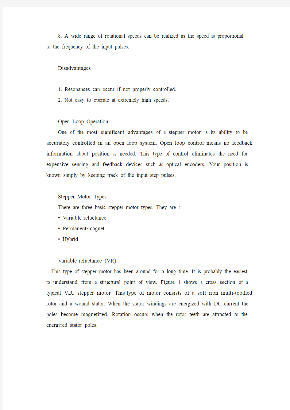
Figure 2 shows the magnetic flux path developed when phase B is energized with winding current in the direction shown. The rotor then aligns itself so that the flux opposition is minimized. In this case the motor would rotate clockwise so that its south pole aligns with the north pole of the stator B at position 2 and its north pole aligns with the south pole of stator B at position 6. To get the motor to rotate we can now see that we must provide a sequence of energizing the stator windings in such a fashion that provides a rotating magnetic flux field which the rotor follows due to magnetic attraction.
Figure 2 Magnetic flux path through atwo-pole stepper motor with a lag betweenthe rotor and stator.
Torque Generation
The torque produced by a stepper motor depends on several factors.
? The step rate
? The drive current in the windings
? The drive design or type
In a stepper motor a torque is developed when the magnetic fluxes of the rotor and stator are displaced from each other. The stator is made up of a high permeability magnetic material. The presence of this high permeability material causes the magnetic flux to be confined for the most part to the paths defined by the stator structure in the same fashion that currents are confined to the conductors of an electronic circuit. This serves to concentrate the flux at the stator poles. Thetorque output produced by the motor is proportional to the intensity of the magnetic flux generated when the winding is energized.
The basic relationship which defines the intensity of the magneticflux is defined by:
H = (N ×i) ÷ l where:
N = The number of winding turns
i = current
H = Magnetic field intensity
l = Magnetic flux path length
This relationship shows that the magnetic flux intensity and consequently the torque is proportional to the number of winding turns and the current and inversely proportional to the length of the magnetic flux path. From this basic relationship one can see that the same frame size stepper motor could have very different torque output capabilities simply by changing the winding parameters. More detailed information on how the winding parameters affect the output capability of the motor can be found in the application note entitled “DriveCircuit Basics”.
Stepping Modes
The following are the most common drive modes.
? Wave Drive (1 phase on)
? Full Step Drive (2 phases on)
? Half Step Drive (1 & 2 phases on)
? Micro stepping (Continuously varying motor currents)
For the following discussions please refer to the figure 3.
Figure 3 Unipolar and bipolar wound stepper motors.
In Wave Drive only one winding is energized at any given time. The stator is energized according to the sequence A B A B and the rotor steps from position
8 2 4 6. For unipolar and bipolar wo und motors with the same winding parameters this excitation mode would result in the same mechanical position. The disadvantage of this drive mode is that in the unipolar wound motor you are only using 25% and in the bipolar motor only 50% of the total motor winding at any given time. This means that you are not getting the maximum torque output from the motor.
In Full Step Drive you are energizingtwo phases at any given time.The stator is energized according to the sequence AB A B A B AB and the rotor steps from position 1 3 5 7 . Full step mode results in the same angular movement as 1 phase on drive but the mechanical position is offset by one half of a full
step. The torque output of the unipolar wound motor is lower than the bipolar motor (for motors with the same winding parameters) since the unipolar motor uses only 50% of the available winding while the bipolar motor uses the entire winding.
Half Step Drive combines both wave and full step (1&2 phases on) drive modes. Every second step only
one phase is energized and during the other steps one phase on each stator. The stator is energized according to the sequence AB B A B A A B B A B A and the rotor steps from position 1 2 3 4 5 6 7 8. This results in angular movements that are half of those in 1- or 2-phases-on drive modes. Half stepping can reduce a phenomena referred to as resonance which can be experienced
in 1- or 2-phases-on drive modes.
The excitation sequences for the above drive modes are summarized in Table 1. Table 1. Excitation sequences for different drive modes
In Microstepping Drive the currents in the windings are continuously varying to be able to break up one full step into many smaller discrete steps. More information on microstepping can be found in the microstepping chapter.
Single Step Response and Resonances
The single-step response characteristics of a stepper motor is shown in figure 4.
Figure 4 Single step response vs. time.
When one step pulse is applied to a stepper motor the rotor behaves in a manner as defined by the above curve.The step time t is the time it takes the motor shaft to rotate one step angle once the first step pulse is applied. This step time is highly dependent on the ratio of torque to inertia (load) as well as the type of driver used.
Since the torque is a function of the displacement it follows that the acceleration will also be. Therefore, when moving in large step increments a high torque is developed and consequently a high acceleration. This can cause overshots and ringing as shown. The settling time T is the time it takes these oscillations or ringing to cease. In certain applications this phenomena can be undesirable. It is possible to reduce or eliminate this behaviour by microstepping the stepper motor. For more information on micro stepping please consult the microstepping note.
Stepper motors can often exhibit a phenomena refered to as resonance at certain step rates. This can be seen as a sudden loss or drop in torque at certain speeds which can result in missed steps or loss of synchronism. It occurs when the input step pulse
rate coincides with the natural oscillation frequency of the rotor. Often there is a resonance area around the 100 – 200 pps region and also one in the high step pulse rate region. The resonance phenomena of a stepper motor comes from its basic construction and therefore it is not possible to eliminate it completely. It is also dependent upon the load conditions. It can be reduced by driving the motor in half or micro stepping modes.
中文译文
步进电机基础
[林铁国,张建勋.基于DSP的微控制器的步进电机控制和自动化, 2004 。第五次世界代
表大会第五册15-19日, 2004年6月.]
步进电机是一种机电设备,它把电气转换成脉冲离散机械动作。当电器指挥脉冲以正确的顺序应用时,轴或主轴步进电机旋转一步离散增量。电动机转动对这些应用输入脉冲有几种直接联系。应用脉冲的序列与电机轴旋转方向直接相关。电机轴旋转的速度与输入脉冲的频率直接相关,旋转的长度与应用输入脉冲的数字输入直接相关。
步进电机的优点和缺点:
优点:1. 电机旋转的角度与脉冲输入成正比;
2. 如果绕组被加强,电机转距会完全静止;
3.因为良好的步进电机有3%-5%的准确率而且即使有错误,也不是从一步
累计到另一步的,所以步进机能够精确定位并且可重复性运动;
4.对启动/停止/旋转有良好的反应;
5. 因为电机上没有连接点,所以它非常可靠。电机的寿命是由轴承的寿命决定
的;
6.电机对数字输入脉冲的反应提供提供开放环路的控制,这使得电机控制起来比
较容易而且不那么昂贵;
7.在直接地结合对轴的装载时,它是可能达到非常低速的同步自转的;
8. 当速度与输入脉冲的频率成比例时,就可以实现大范围的旋转速度
缺点:1. 如果不恰当地控制可能会发生共鸣;
2. 如果速度太快就不易操纵;
开环操作:
步进机的一个显著优势就是它的功能能在开环系统中被准确控制。开环控制意味着对需要的位置是没有反馈信息的。这类型的控制系统消除了对昂贵感应与反馈设置例如对光学编码器等的需要。通过跟踪输入脉冲就能很容易地知晓您所处的位置。
步进机类型:
有三种步进机类型,它们是:
1.可变磁阻型;
2.永久磁场型;
3.杂交复合型;
可变磁阻型:
这种步进电机已存在了很长的时间.从结构的观点来看它可能是最容易理解的。图1显示了典型的可变磁阻型步进机的截面。这种电机是由一个软铁多齿转子和创伤定子构成的。当定子绕组电源被直流电强化,电机的两极就被磁化了。当转子齿被吸引到磁化的两极时,电机就转动了。
图1 可变磁阻型步进机的截面
永久磁场型:
这种电机通常被称作“罐”或“倾斜”电机。这种永久磁场型电机是一种低成本和低分辨率类型的电机,它典型的分辨角度是7.5°到15°。永久磁场型步进电机顾名思义有永磁材料添加到电机结构中。与可变磁阻型电机相比,这种类型的电机转子不再有齿,取而带之的是转子随着电机南北两极交替位于一条直线平行于转子轴而磁化。这些磁化的转子级为电机提供一种增加的磁性涨潮强度,也因此这种类型的步进机与可变磁阻型步进机相比具有更高级的转距特征。
杂交复合型:
混合型步进机比永久磁场型步进机要贵,但是因为考虑到了步距,转距以及速度,它的表现要比永久磁场型步进机表现优良。对于杂交复合型步进机而言,典型的步距角度是从 3.6°到 0.9°。混合式步进机中和了可变磁阻型步进机和永久磁场型步进机的优良特征。转子像可变磁阻型步进机一样是多齿型的,并含有磁化轴同心圆磁铁绕其轴。转子上的齿提供了一条更好的路径,它有助于有助于引导磁通量为首选地点气隙。与以上两种类型的步进机相比,这进一步增加了定位、控股及动态转矩特性。
两种最常用类型的步进机是永久磁场型步进机和混合型步进机。如果一个设计师不知道哪种步进机是最适合其应用需求的,他应该首先评估挑选永久磁场型的,因为它通常是最便宜的。如果永久磁场型步电机不行的话,那么混合型的也许会是合适的选择。
同样,还存在一些特殊类型的步进机。一种是盘式永磁步进机。这里的转子是用稀土永磁材料制成的,设计得像一张唱片。(见图2)这型发动机具有一些优势,例如很低的惰性和没有围绕在两定子之间的优化磁流路。这些品性在某些应用中是必不可少的。
图2 磁通通过两杆步进电机的转子和定子之间
尺寸和功能:
除了按自己的步距角度分类之外,步进机也按与电机直径相关的整体尺寸来分类。例如一个尺寸为11的步进机直径大约为1.1英寸。同样大小为23的步进机直径为2.3英寸( 58毫米)。整体大小相同的步进机由于属于不同的机子在机身长度上可能会有变化,作为一般规则,某一特定尺寸电动机的可供输出力矩随机身长度的增加而增加。
功率级集成电路驱动步进电机一般由对非常小电机的1瓦特到对大型电机的10-20瓦特。在汽车制造商的资料里,电机的最高功耗水平和热量限制很少明确表示出来。为了证明这一点,我们必须运用关系式P=V×I,例如:大小为23的步进电机,每阶段可在额定的6V和1A,因此,两相电源的电动机的额定功耗为12瓦特。测量步进机的热量挥发水平,这是通常的做法。在静止的空气中,步进机的热量上升到65°。如果电动机可以挂载到一个散热器也常常能够增加允许功耗水平,这一点很重要,因为步进机的设计要求它应该从它的最高功耗、尺寸输出功率或者尺寸输出成本的角度来加以使用。
何时使用步进电机
当需要控制运动时,步进电机可以成为很好的选择。当你需要控制旋转角度,速度,位置和同步时,它们能够在应用中发挥优势。因为自身固有的优势,步进电机在多种不同的应用种都找到了它们的位置。其中一些项目包括打印机、绘图仪、精品办公设备、电脑硬盘、医疗设备、传真机,汽车和更多。
旋转磁场
当一相绕组的步进电机电源电流与磁是发达的定子,电流的方向是由“右手定则”决定的。“右手定则”规定:“若磁力线垂直进入右手,四指所指方向为导线中感应电流的方向,则大拇指所指的方向就是磁场的方向。”
图5显示了磁通路径发展,B阶段随着所示绕组电流的方向而加强。转子控制自己使反向流量最低。在这种情况下将电机顺时针转动,使南极配合北极的定子B在位置2和北极配合南极定子B在位置6 ,获得电机轮换。为了让步进电机转
动,我们现在可以看到,我们必须提供一组序列定子,这组定子可以提供一个旋转磁场,由于磁吸引力,带动定子转动。
扭矩代转矩控制取决于若干因素:
.步距;
.绕组驱动电流;
.驱动设计或类型;
在一个步进电机中,当定子和转子的磁流量彼此取代时,扭距才发生变化。定子是由高渗透磁性物质组成的,这种高渗透磁性物质的存在导致磁流量被部分地限定,这有助于磁流量集中在定子两极。当绕组加强时,电机的扭力输出与磁流量产生的强度成比例。
界定磁流量的基本项:
H = (N ×i) ÷ l
N :匝数
i :电流
H:磁场强度
L:磁流量路径长度
这种关系表明磁场强度与扭距同匝数和电流成正比,与磁流量路径长度成反比。从这一基本关系可以看出可以看出同样的磁流量路径长度,不同的步进电机通过改变绕组参数可以有不同的输出力矩。更详细的资料关于绕组参数如何影响步进机输出量可以在题为“驱动电流基础”的应用说明中找到。
步进模式
下列各项是最通常的驱动模式
1. 波动驱动(在1 状态)
2. 半步驱动(在2状态)
3. 全步驱动(在1和2状态)
4. 细分步进(不断地改变电机的电流)
对于下列的讨论如图3所示
图3 单极步进电机
在波动驱动中只有一个线圈转动在任何接通时间。按照A → B → A → B的顺序驱动和转子的转动为8 → 2 → 4→ 6。对于和相同的参数的单极和有两极的电机,这一个脉冲模式会运行相同的机械位置。这一个驱动模式的缺点是在单极的电机只有在只有25% 被使用和在有两极的电机中在任何的运行时间的只有 50% 的总计电机转动。这表示你没有在从电机运行中得到最大的转力矩输出。
在全步驱动时在任何接同时间有2个脉冲周期。按照AB → A B→ AB→A B和转子的转动为1 → 3 → 5 → 7。全部驱动在驱动方式和1状态相同有角动但是机械的移动位置全部被弥补一半。因为单极的电机使用,单极电机的转力矩输出比两极的电机 (对于和相同的参数马达) 低只有 50% , 有两极的电机可以用全周期。
半步驱动整合了波动和全部驱动 (在1和2 脉冲)的驱动形式。每两个脉冲逐步运行被激活并在其他运行周期在每个固定的状态。按照AB → B → AB → A→ AB → B → AB → A和转子转动为1 → 2 → 3→ 4 → 5 → 6 → 7 → 8结果在角运动,有一半是在1或2阶段--驱动方式. 半步驱动,可以减少的现象称为共振,可以在经历了1或2阶段的驱动方式。
上述驱动方式激发触发顺序如表1
表1 驱动方式激发触发顺序
步进驱动电流绕组不断改变形成许多较小的离散步骤. 更多信息细分,可以发现在步进。
单步响应
步进电机单步响应特性如图4所示
如图4 步进电机单步响应特性
当脉冲采用了步进电机转子的运行方式到上述步骤曲线时间t的时候,它采取的电机轴转动一个步距角,第一步是脉冲应用. 这一步的时间是高度依赖比率转矩惯性(负载) ,以及使用的驱动种类。由于扭矩是一个函数的位移所以接下来的加速度也将. 因此,当移动大型梯级递增高转矩发达,因此一个高加速度. 这可引起了长鸣所示. 沉降时间T是要花时间,因此这些振荡或铃声停止. 在某些应用这一现象可不可取. 它可以减少或消除这种行为的细分步进电机. 由于扭矩是一个函数的位移所以接下来的加速度也将. 因此,当移动大型梯级递增高转矩发达,因此一个高加速度. 沉降时间T是要花时间,因此这些振荡或周期停止. 在某些应用这一现象. 它可以减少或消除这种行为的细分步进电机.
步进电机往往能表现出的现象称为共振, 这可以看作一个突然丧失或下降时转矩转速一定能够导致漏步骤或失去同步. 当它发生时,输入阶跃脉冲率刚好与自然振荡频率有关. 共振现象的一个步进电机来自其基础设施建设,因此不可能消除. 这也是取决于负载的情况. 它可以减少电机驱动在半步或微步进模式。
企业成本控制外文翻译文献
企业成本控制外文翻译文献(文档含英文原文和中文翻译)
译文: 在价值链的成本控制下减少费用和获得更多的利润 摘要: 根据基于价值链的成本管理理念和基于价值的重要因素是必要的。首先,必须有足够的资源,必须创造了有利的价值投资,同时还需要基于客户价值活动链,以确定他们的成本管理优势的价值链。其次,消耗的资源必须尽量减少,使最小的运营成本价值链和确保成本优势是基于最大商业价值或利润,这是一种成本控制系统内部整个视图的创建和供应的具实践,它也是一种成本控制制度基于价值链,包括足够的控制和必要的资源投资价值的观点,创建和保持消费的资源到合理的水平,具有价值的观点主要对象的第一个因素是构造有利的价值链,从创造顾客价值开始;第二个因素是加强有利的价值链,从供应或生产客户价值开始。因此它是一个新型的理念,去探索成本控制从整个视图的创建和供应的商品更盈利企业获得可持续的竞争优势。 关键词:成本控制,价值链,收益,支出,收入,成本会计 1、介绍 根据价值链理论,企业的目的是创造最大的顾客价值;和企业的竞争优势在于尽可能提供尽可能多的价值给他们的客户,作为低成本可能的。这要求企业必须首先考虑他们是否能为顾客创造价值,和然后考虑在很长一段时间内如何创造它。然而,竞争一直以“商品”(或“产品”)作为最直接的载体,因此,传统的成本控制方法主要集中在对“产品”和生产流程的过程。很显然,这不能解决企业的问题,企业是否或如何能为客户创造价值。换句话说,这至少不能从根本上解决它。 因此,企业必须首先投入足够的资源,以便他们能够创建客户值取向,然后提供它以最少的资源费用。所以在整个视图中对价值创造和提供整体的观点来控制成本,它可以为客户提供完美的动力和操作运行机制运行成本的控制,也可以从根本上彻底克服了传统的成本控制方法的缺点,解决了无法控制的创造和供应不足的真正价值。基于此,本文试图从创作的整体观讨论成本控制提供价值并探讨实现良性循环的策略,也就是说,“创造价值投资成本供应价值创造价值”。 2、成本及其控制的基于价值链理念 2.1基于价值链的成本观念 根据价值链理论,如果企业是要被客户接受,它必须创造和提供能满足其客户的价值。因此,成本(价值或资源支付费用)这不离为创造和提供顾客价值的活动,其活动的价值链。因此,我们应该从价值链角度看成本的重要。
步进电机常识与矩频曲线
步进常识 1. 什么是步进电机? 步进电机是一种将电脉冲转化为角位移的执行机构。通俗一点讲:当步进驱动器接收到一个脉冲信号,它就驱动步进电机按设定的方向转动一个固定的角度(及步进角)。您可以通过控制脉冲个数来控制角位移量,从而达到准确定位的目的;同时您可以通过控制脉冲频率来控制电机转动的速度和加速度,从而达到调速的目的。 2. 步进电机分哪几种? 步进电机分三种:永磁式(PM ,反应式(VR和混合式(HB 永磁式步进一般为两相,转矩和体积较小,步进角一般为7.5 度或15 度;反应式步进一般为三相,可实现大转矩输出,步进角一般为1.5 度,但噪声和振动都很大。在欧美等发达国家80 年代已被淘汰;混合式步进是指混合了永磁式和反应式的优点。它又分为两相和五相:两相步进角一般为1.8 度而五相步进角一般为0.72 度。这种步进电机的应用最为广泛。 3. 什么是保持转矩(HOLDING TORQUE? 保持转矩(HOLDINGORQUE是指步进电机通电但没有转动时,定子锁住转子的力矩。它是步进电机最重要的参数之一,通常步进 电机在低速时的力矩接近保持转矩。由于步进电机的输出力矩随速度的增大而不断衰减,输出功率也随速度的增大而变化,所以保持转矩就成为
了衡量步进电机最重要的参数之一。比如,当人们说2N.m 的步进电机,在没有特殊说明的情况下是指保持转矩为2N.m 的步进电机。 4. 什么是DETENT TORQU起动转扭) DETENTTORQU是指步进电机没有通电的情况下,定子锁住转子的力矩。DETEN T ORQUEE国内没有统一的翻译方式,容易使大家产生误解;由于反应式步进电机的转子不是永磁材料,所以它没有DETENT TORQ U E 5. 一般步进电机的精度为步进角的3-5%,且不累积。 6. 步进电机温度过高首先会使电机的磁性材料退磁,从而导致力矩下降乃至 于失步,因此电机外表允许的最高温度应取决于不同电机磁性材料的退磁点;一般来讲,磁性材料的退磁点都在摄氏130 度以上,有的甚至高达摄氏200 度以上,所以步进电机外表温度在摄氏80-90 度完全正常。7. 当步进电机转动时,电机各相绕组的电感将形成一个反向电动势;频率越 高,反向电动势越大。在它的作用下,电机随频率(或速度)的增大而相电流减小,从而导致力矩下降。 8. 为什么步进电机低速时可以正常运转, 但若高于一定速度就无法启动, 并伴 有啸叫声?
机器人外文翻译
英文原文出自《Advanced Technology Libraries》2008年第5期 Robot Robot is a type of mechantronics equipment which synthesizes the last research achievement of engine and precision engine, micro-electronics and computer, automation control and drive, sensor and message dispose and artificial intelligence and so on. With the development of economic and the demand for automation control, robot technology is developed quickly and all types of the robots products are come into being. The practicality use of robot products not only solves the problems which are difficult to operate for human being, but also advances the industrial automation program. At present, the research and development of robot involves several kinds of technology and the robot system configuration is so complex that the cost at large is high which to a certain extent limit the robot abroad use. To development economic practicality and high reliability robot system will be value to robot social application and economy development. With the rapid progress with the control economy and expanding of the modern cities, the let of sewage is increasing quickly: With the development of modern technology and the enhancement of consciousness about environment reserve, more and more people realized the importance and urgent of sewage disposal. Active bacteria method is an effective technique for sewage disposal,The lacunaris plastic is an effective basement for active bacteria adhesion for sewage disposal. The abundance requirement for lacunaris plastic makes it is a consequent for the plastic producing with automation and high productivity. Therefore, it is very necessary to design a manipulator that can automatically fulfill the plastic holding. With the analysis of the problems in the design of the plastic holding manipulator and synthesizing the robot research and development condition in recent years, a economic scheme is concluded on the basis of the analysis of mechanical configuration, transform system, drive device and control system and guided by the idea of the characteristic and complex of mechanical configuration,
步进电机的单片机控制外文翻译
附录2:英文资料及其中文翻译 Stepper motor is an electrical pulse will be converted into angular displacement of the implem enting agencies. Put it in simple language-speaking: When the stepper drive pulse signal to a r eceiver, it drives stepper motor rotation direction by setting a fixed point of view (and the ste p angle). You can control the number of pulses to control the amount of angular displacement, so as to achieve the purpose of accurate positioning; At the same time, you can by controllin g the pulse frequency to control the motor rotation speed and acceleration, so as to achieve th e purpose of speed. Stepper motor directly from the AC-DC power supply, and must use special equipment - stepp er motor drive. Stepper motor drive system performance, in addition to their own performance with the motor on the outside, but also to a large extent depend on the drive is good or bad. A typical stepper motor drive system is operated by the stepper motor controller, stepper mot or drives and stepper motor body is composed of three parts. Stepper motor controller stepper pulse and direction signal, each made of a pulse, stepper motor-driven stepper motor drives a rotor rotating step angle, that is, step-by-step further. High or low speed stepper motor, or spe ed, or deceleration, start or stop pulses are entirely dependent on whether the level or frequenc y. Decide the direction of the signal controller stepper motor clockwise or counterclockwise rot ation. Typically, the stepper motor drive circuit from the logic control, power driver circuit, pr otection circuit and power components. Stepper motor drive controller, once received from the direction of the signal and step pulse, the control circuit on a pre-determined way of the electr ical power-phase stepper motor excitation windings of the conduction or cut-off signal. Control circuit output signal power is low, can not provide the necessary stepping motor output powe r, the need for power amplifier, which is stepper motor driven power drive part. Power stepper motor drive circuit to control the input current winding to form a space for rotating magnetic field excitation, the rotor-driven movement. Protection circuit in the event of short circuit, ove rload, overheating, such as failure to stop the rapid drive and motor. Motor is usually for the permanent magnet rotor, when the current flows through the stator wi ndings, the stator windings produce a magnetic field vector. The magnetic field will lead to a rotor angle of rotation, making a pair of rotor and stator magnetic field direction of the magne tic field direction. When the stator rotating magnetic field vector from a different angle. Also as the rotor magnetic field to a point of view. An electrical pulse for each input, the motor r otation angle step. Its output and input of the angular displacement is proportional to the pulse s, with pulse frequency proportional to speed. Power to change the order of winding, the elect rical will be reversed. We can, therefore, control the pulse number, frequency and electrical po wer windings of each phase to control the order of rotation of stepper motor. Stepper motor types: Permanent magnet (PM). Magnetic generally two-phase stepper, torque and are smaller and gen erally stepping angle of 7.5 degrees or 15 degrees; put more wind for air-conditioning. Reactive (VR), the domestic general called BF, have a common three-phase reaction, step angl e of 1.5 degrees; also have five-phase reaction. Noise, no torque has been set at a large numb er of out. Hybrid (HB), common two-phase hybrid, five-phase hybrid, three-phase hybrid, four-phase hybri d, two-phase can be common with the four-phase drive, five-phase three-phase must be used w ith their drives;
智能汽车中英文对照外文翻译文献
智能汽车中英文对照外文翻译文献 (文档含英文原文和中文翻译) 翻译: 基于智能汽车的智能控制研究 摘要:本文使用一个叫做“智能汽车”的平台进行智能控制研究,该小车采用飞思卡尔半导体公司制造的MC9S12DG128芯片作为主要的控制单元,同时介绍了最小的智能控制系统的设计和实现智能车的自我追踪驾驶使用路径识别算法。智能控制智能车的研究包括:提取路径信息,自我跟踪算法实现和方向和速度控制。下文介绍了系统中不同模块的各自实现功能,最重要部分是智能车的过程智能控制:开环控制和闭环控制的应用程序包括增量式PID控制算法和鲁棒控制算法。最后一步是
基于智能控制系统的智能测试。 关键词:MC9S12DG128;智能控制;开环控制;PID;鲁棒; 1.背景介绍 随着控制理论的提高以及信息技术的快速发展,智能控制在我们的社会中发挥着越来越重要的作用。由于嵌入式设备有小尺寸、低功耗、功能强大等优点,相信在这个领域将会有一个相对广泛的应用,如汽车电子、航空航天、智能家居。如果这些技术一起工作,它将会蔓延到其他领域。为了研究嵌入式智能控制技术,“智能汽车”被选为研究平台,并把MC9S12DG128芯片作为主控单元。通过智能控制,智能汽车可以自主移动,同时跟踪的路径。 首先,本文给读者一个总体介绍智能车辆系统的[2、3]。然后,根据智能车辆的智能控制:提取路径信息,自我跟踪算法实现中,舵机的方向和速度的控制。它提供包括了上述四个方面的细节的智能车系统信息。此外,本文强调了智能车的控制过程应用程序包括开环控制、闭环增量PID算法和鲁棒算法。 2.智能车系统的总体设计 该系统采用MC9S12DG128[4]作为主芯片,以及一个CCD传感器作为交通信息收集的传感器。速度传感器是基于无线电型光电管的原理开发。路径可以CCD传感器后绘制收集的数据,并且系统计算出相应的处理。在同时,用由电动马达速度测试模块测量的智能汽车的当前速度进行响应的系统。最后,路径识别系统利用所述路径信息和当前的速度,以使智能汽车在不同的道路条件的最高速度运行。图1示出了智能车辆系统的框图。
步进电机基本知识
步进电机基本知识(2009-01-08 13:51:30) 1、步进电机:是一种将电脉冲转化为角位移或线位移的执行机构。其特点是没有积累误差(精度为100%),广泛应用于各种开环控制。 2、步进电机分类:永磁式(PM),反应式(VR),混合式(HB)。 3、保持转矩:是指步进电机通电,但没有转动时,定子锁住转子的力矩。 4、精度:为步进角的3~5%,且不累积。 5、细分驱动器:是通过改变相邻(A,B)电流的大小,以改变合成磁场的夹角来控制步进电机的运转的。细分功能完全是由驱动器靠精确控制电机的相电流所产生的,与电机无关。对于2,4相电机,细分后的步距角等于电机的整步步距角除以细分数。对于3相反应式电机,细分后的步距角等于电机的半步步距角除以细分数。 6、步距角:对应一个脉冲信号,电机转子转过的角位移用θ表示。0.9°/1.8°(表示半步工作时为0.9°,整步工作时为1.8°)此步距角为电机固有步距角。 7、相数:产生不同对极N、S磁场的激磁线圈对数。常用m表示。 8、失步:电机运转时运转的步数,不等于理论上的步数。称之为失步。 9、最大空载起动频率:电机在某种驱动形式、电压及额定电流下,在不加负载的情况下,能够直接起动的最大频率。 10、最大空载运行频率:电机在某种驱动形式,电压及额定电流下,电机不带负载的最高转速频率。 11、步进电机最好不使用整步状态,整步状态时振动大。 12、电机的位置和速度由导电次数(脉冲数)和频率成一一对应关系。方向由导电顺序决定。控制步进脉冲信号的频率,可以对电机进行精确调速;控制步进脉冲的个数,可以对电机进行精确定位。
13、步进电机驱动器:是把计算机控制系统提供的弱信号放大为步进电机能够接受的强电流信号。 14、拍数:是完成一个磁场周期性变化所需脉冲数。指电机转过一个齿距角所需脉冲数。 15、脱机信号free:此信号为选用信号,并不是必须要用的,只有在一些特殊情况下使用,此端为低电平有效,这时电机处于无力矩状态;此端为高电平或悬空不接时此功能无效,电机可正常运行,此功能若用户不采用,只需将此端悬空即可。 16、CP脉冲宽度一般要求不小于2us。 17、CP电平方式:对于共阳接法的驱动器要求为负脉冲方式,脉冲状态为低电平,无脉冲时为高电平;对于共阴接法的驱动器要求为正脉冲方式,脉冲状态为高电平,无脉冲时为低电平。 18、dir信号:一定要在电机降速停止后再换向。 19、步进电机在启动时,必须有升速过程;在停止时必须有降速过程,一般来说升速过程和降速过程规律相同。特例:步进电机运行速度不超过突跳频率,这时不存在升降速问题。 20、自动半电流功能:驱动机在步进脉冲信号停止施加2S左右,会自动进入半电流状态,这时电机相电流为运行时的一半,以减少功耗和保护电机。 21、细分优点:完全消除了电机的低频振荡。 22、步进电机的工作性能在很大程度上取决于所使用的驱动电路的类型和参数。 23、常用的有两相,四相混合式步进电机。 24、电机是有内阻的感性负载。 25、步进电机驱动方式:恒压,恒流,恒流斩波,使同样电机输出更大速度和功率。 26、步进电机启动:A、低初速度,低加速度阶段
外文翻译(土木专业)
模拟在火灾情况下加载对构造柱行为的影响 作者: 阿尼尔阿加瓦尔,普渡大学西拉法叶,在47906,anilag@https://www.360docs.net/doc/9110541875.html, 阿米特阁下瓦玛,普渡大学西拉法叶,在47906,ahvarma@https://www.360docs.net/doc/9110541875.html, 本文介绍了在光纤梁柱的有限元建模发展的基础上,模拟梁柱和其他构件在火灾高温情况下受荷的结构行为。几个这样的单元可以结合起来:(一)模型结构构件和框架(二)在火灾情况下分析它们,有限元程序是在一个土著有限元分析程序,使用改进的牛顿拉夫逊(星期日)迭代求解算法进行非线性分析。该文件还为简单的基准的方案问题以及钢柱在最近进行的火灾测试提供了有限元的有限验证。审定、采用有限元参数进行分析,以探讨在火灾情况下钢柱负荷强度的结构参数和约束作用 1.0简介 目前的建筑法规(例如,国际生物伦理委员会2005年)强调规范建筑钢结构防火抗震设计。用标准的ASTM E119进行测试以确定各组成部分的防火等级。由于工具简单,火灾的标准测试结果的适用性是有限的,通过这些测试推断出结果,提供一个在现实的火灾情况下洞察整个结构和各个组成部分的基本行为的途径。目前,急需一个简单的分析模型和方法,以用来从一定精度上模拟在标准火灾作用下,个别结构构件的行为以及它们之间相互作用。这些模型必须基于基本原则,适用于参数研究,同时能容易地探索设计方案。本文论述了一个结论的发展和验证,即一个简单的2个节点的有限梁柱元素,可以用来模拟和分析在火灾荷载下整个结构。对一些参数进行研究,探讨边界条件和其它的约束作用,以及钢柱受到的轴向和热负荷作用下的破坏。 2.0纤维配方基于2 -节点有限元 一个2节点有限元已制订的c0曲率在节点的连续性和一个三次埃尔米特多项式形函数。荷载被假定为只作用在一个元素的节点上,这个元素有两个结合点,在每个端部各一个,拟议的梁柱元素设计是考虑到结构的几何非线性和材料非线性。完整的工具,包括元素和计算程序,有能力对只承受弯曲变形或轴向变形的任何截面做出分析。以下分节讨论了该模型的突出问题。 2.1热负荷 该元素能将热膨胀的影响和由于温度变化所引起的材料性能的改变结合起来。全截面纤维可以被分配在不同的温度和在温度非均匀情况下分布,压力和弯曲的情况也是全截面分布的,使截面图保持水平,外部作用平衡外部作用。香港开发的分析程序(2007)可以用来计算给定播映时间的温度曲线整个路段的温度。计算工具得到了进一步的修改,以允许用户通过宽翼缘部分(图1)给定的7个点,输入时间温度曲线。该方案在特定值中插值以计算每个截面纤维的温度。 2.2材料性能 该方案有能力建模钢、钢筋混凝土,以及诸如钢管混凝土管(桂林工学院)的复合元素。变温单轴应力应变曲线必须是一节中使用的特定的材料。目前的工作,重点是在钢柱。博爱医院所提出的温度依赖性钢的应力应变曲线(2001)已用
基于单片机的步进电机控制系统设计外文翻译
毕业设计(论文)外文资料翻译 学院:机械工程学院 专业:机械设计制造及其自动化 姓名: 学号:XXXXXXXXXX 外文出处:《Computational Intelligence and (用外文写)Design》 附件: 1.外文资料翻译译文;2.外文原文。 注:请将该封面与附件装订成册。
附件1:外文资料翻译译文 基于微型计算机的步进电机控制系统设计 孟天星余兰兰 山东理工大学电子与电气工程学院 山东省淄博市 摘要 本文详细地介绍了一种以AT89C51为核心的步进电机控制系统。该系统设计包括硬件设计、软件设计和电路设计。电路设计模块包括键盘输入模块、LED显示模块、发光二极管状态显示和报警模块。按键可以输入设定步进电机的启停、转速、转向,改变转速、转向等的状态参数。通过键盘输入的状态参数来控制步进电机的步进位置和步进速度进而驱动负载执行预订的工作。运用显示电路来显示步进电机的输入数据和运行状态。AT89C51单片机通过指令系统和编译程序来执行软件部分。通过反馈检测模块,该系统可以很好地完成上述功能。 关键词:步进电机,AT89C51单片机,驱动器,速度控制 1概述 步进电机因为具有较高的精度而被广泛地应用于运动控制系统,例如机器人、打印机、软盘驱动机、绘图仪、机械式阀体等等。过去传统的步进电机控制电路和驱动电路设计方法通常都极为复杂,由成本很高而且实用性很差的电器元件组成。结合微型计算机技术和软件编程技术的设计方法成功地避免了设计大量复杂的电路,降低了使用元件的成本,使步进电机的应用更广泛更灵活。本文步进电机控制系统是基于AT89C51单片机进行设计的,它具有电路简单、结构紧凑的特点,能进行加减速,转向和角度控制。它仅仅需要修改控制程序就可以对各种不同型号的步进电机进行控制而不需要改变硬件电路,所以它具有很广泛的应用领域。 2设计方案 该系统以AT89C51单片机为核心来控制步进电机。电路设计包括键盘输入电路、LED显示电路、发光二极管显示电路和报警电路,系统原理框图如图1所示。 At89c51单片机的P2口输出控制步进电机速度的时钟脉冲信号和控制步进电机运转方向的高低电平。通过定时程序和延时程序可以控制步进电机的速度和在某一
毕业设计外文翻译
本科生毕业设计(论文)外文翻译毕业设计(论文)题目:悬架系统设计与分析 外文题目:An Overview of Disarray in Active Suspension System 译文题目:主动悬架系统杂谈 学生姓名: XXX 专业:车辆工程1002班 指导教师姓名:田国富 评阅日期:
主动悬架系统杂谈 帕蒂尔,维杰河帕蒂尔,加尼甚 助理教授,机械工程系,A.D.C.E.T,阿什达 摘要:当设计一个悬挂系统时,它的双重目标是尽量减少传到乘客的垂直力量和最大限度地提高轮胎与道路接触以提高操控性和安全性。乘客的舒适性与从车身传递的垂直力有关。这个目标可以通过最小化车身的垂直加速度来实现。过度的车轮行驶,将导致轮胎相对路面的非最佳姿态,从而导致差的操控性和附着力。此外,为了保持良好的操控性,轮胎与路面的最佳接触必须保持在四个轮子上。在传统的悬架系统中,这些特点是冲突的,不符合所有条件。因此,在被动悬架系统的基础上,为了改善主动悬架系统,各种各样的研究工作正在进行中。在本文中各种作品的概述已经完成。考虑到季度汽车模型,本文试图给出关于以往的研究和他们的发现对被动和主动悬架系统的参数。 关键词:主动悬架系统,控制系统,动态,被动悬架,车辆。 1.引言 汽车悬架系统的目的是在不同路况下,能保持良好的操控特性和改善乘坐品质。不同的悬架,满足上述要求的程度不同。虽然,可由设计者的聪明才智来改善,就平均而言,悬架的性能主要取决于悬架使用的类型。按改进的性能可以以升序区分为:与被动,半主动和全主动悬架系统,输入的力通常由液压致动器提供。为主动悬架系统设计的机电致动器的另一种方法将在电子控制和悬架系统之间提供直接接口。 目前,公认的主动悬架有两种形式,一种是制动器和钢板弹簧平行的高带宽主动悬架。第二种是低带宽主动悬架,它的致动器带有一系列的钢板弹簧并且能够控制车身的运动,而簧下质量控制是通过被动阻尼器控制的。汽车悬架的主动控制在传统悬架的基础上又提出了新的改进。主动悬架,包括创建悬挂系统中力的液压致动器。由液压致动器产生的力被用来控制簧上质量的运动,以及簧上和簧下质量之间的相对速度。为了提高车辆的特色,以后将主要对主动悬架的高带宽型进行研究。
步进电机原理介绍
步进电机也叫步进器,它利用电磁学原理,将电能转换为机械能,人们早在20世纪20年代就开始使用这种电机。随着嵌入式系统(例如打印机、磁盘驱动器、玩具、雨刷、震动寻呼机、机械手臂和录像机等)的日益流行,步进电机的使用也开始暴增。不论在工业、军事、医疗、汽车还是娱乐业中,只要需要把某件物体从一个位置移动到另一个位置,步进电机就一定能派上用场。步进电机有许多种形状和尺寸,但不论形状和尺寸如何,它们都可以归为两类:可变磁阻步进电机和永磁步进电机。本文重点讨论更为简单也更常用的永磁步进电机。 步进电机的构造 如图1所示,步进电机是由一组缠绕在电机固定部件--定子齿槽上的线圈驱动的。通常情况下,一根绕成圈状的金属丝叫做螺线管,而在电机中,绕在齿上的金属丝则叫做绕组、线圈、或相。如果线圈中电流的流向如图1所示,并且我们从电机顶部向下看齿槽的顶部,那么电流在绕两个齿槽按逆时针流向流动。根据安培定律和右手准则,这样的电流会产生一个北极向上的磁场。
现在假设我们构造一个定子上缠绕有两个绕组的电机,内置一个能够绕中心任意转动的永久磁铁,这个可旋转部分叫做转子。图2给出了一种简单的电机,叫做双相双极电机,因为其定子上有两个绕组,而且其转子有两个磁极。如果我们按图2a所示方向给绕组1输送电流,而绕组2中没有电流流过,那么电机转子的南极就会自然地按图中所示,指向定子磁场的北极。 再假设我们切断绕组1中的电流,而按图2b所示方向给绕组2输送电流,那么定子的磁场就会指向左侧,而转子也会随之旋转,与定子磁场方向保持一致 接着,我们再将绕组2的电流切断,按照图2c的方向给绕组1输送电流,注意:这时绕组1中的电流流向与图2a所示方向相反。于是定子的磁场北极就会指向下,从而导致转子旋转,其南极也指向下方。 然后我们又切断绕组1中的电流,按照图2d所示方向给绕组2输送电流,于是定子磁场又会指向右侧,从而使得转子旋转,其南极也指向右侧。。 最后,我们再一次切断绕组2中的电流,并给绕组1输送如图2a所示的电流,
外文翻译译文
对整体叶盘加工柔性磨削头的自适应性 Pengbing Zhao & Yaoyao Shi 收稿日期:20135月21日 接受:2013年10月15日 在线发表时间:2013年11月8日 #施普林格出版社伦敦2013 摘要:为提高机械加工时的质量、稳定性、一致性,以及其他加工表面的机械性能,现设计出一款新式的气动的柔性磨头,现分析这款柔性磨头的工作原理,可加工的区域以及实时定位技术。考虑到非直线区域加工死区、未知系统功能以及气动伺服系统性能的不确定干扰的影响,提出一种基于扩张状态观测器(ESO)的自适应滑模控制(ASMC),ESO是被用来估计系统状态变量以及采用一种自适应率来补偿输入加工死区。最后,闭环系统的稳定性由李亚普诺夫理论(Lyapunov theory)确定。实验结果表明了ESO的完美估计,以及ASMC与传统的PID控制相比有着更强的抗干扰能力,ASMC可以实现亚微粒级别之内控制的精确程度。磨削实验说明这种方法可以缩减近乎50%的叶片表面波状起伏和粗糙度,以及降低大约22.93%的形状误差。 关键词:叶片磨削工艺气动系统滑模控制 1 介绍 叶片是为航空发动机设计的一种新式零件,是一种薄壁整体结构的复杂零件,复杂曲面以及难切割材料。考虑到不同的几何尺寸,材料以及叶片的批量大小,以下有几种加工方法,例如磨削,电化学加工(ECM),以及可以分为水槽电火花加工(SEDM)和电缆电火花加工(WEDM)的电火花加工(EDM)。有几种铣削加工过程依靠特殊的叶片几何形状。次摆线铣削是其中一种最新发展的方法,这种方法可以实现很高的材料切除速率和低的工具磨损。SEDM是一种经
济的叶片粗加工方式,特别是Ni基合金材料的叶片。随着电机的发展,WEDM 可以实现高的材料切除率和切割率,同时也可以应用于叶片的粗加工上。为了大批量生产,ECM或许是叶片生产最高效的方法,ECM没有工具磨损而且可以实现更好的表面加工质量同时不会产生白层或者热影响区。 以上提到的几种加工方法主要是用于叶片的粗加工,且对叶片的表面质量有很高的需求。本文的重点是叶片表面的加工完成过程,例如最后的加工,通过磨削来保证尺寸精度和表面质量,这个过程可以提升表面平滑度和完整性,改善残余应力分布,也可以增强疲劳强度和抗腐蚀性。超声振动磨削的作用已经清楚,其可以显著降低工件表面的粗糙度而且在加工硬脆性材料时特别有效。实验证明超声振动磨削可以减少磨削时的正应力和相当的热损害。现提出电缆电火花磨削和一种由此而生的表面粗糙度在线估计方法。金刚石电火花磨削将金刚石磨削和电火花加工结合起来,是一种加工电传导性硬质材料的新式加工工艺。在实现超精密表面硬化和电解磨削修整的脆性材料的加工过程中,其有效地增加了材料切除效率以及砂轮的磨损。对于提出的电化学磨削(ECG),和电解液浓度、工作电压、切割深度的影响,以及加工过程中的电解液流动速率已经做了研究,以及依靠响应曲面法的ECG多响应优化已经被设计出来了。流动磨料加工是用来完成加工高的内表面质量,难以进入的零件,以及外轮廓的一种方法。由阿尔门试片被介质影响完成可塑性变形振动模型的过程调查,和数值模型的边缘舍入的脆性材料振动建立完成。拖动研磨表面改性的研究,以及减少径向前角和拖后整理工序前沿的准备导致硬质合金立铣刀刀具寿命增加。机械化学磨削是一个优异的加工过程,是将化学和机械磨削的优点相结合的固定磨料加工。一种机器人的从几何复杂的工件去除材料的砂带磨削的有效过程,以及仿真平台设计的最优区磨削参数。为了在整个磨削过程中保持一个恒定的接触力,提出了一种机器人砂带磨削的新方法。 本文提出了一个新式的多轴数控磨削方法,可以提高加工质量,稳定性,一致性以及叶片其他表面的机械性能,降低生产成本,提高加工效率。作为一个必要的装配,在这个数控磨削试机时,柔性磨头是一个复杂的气动伺服系统,表面的加工精度取决于磨头的定位精度。然而,可压缩气体,活塞与气缸壁之间的摩擦,阀的死区,和其他非线性区域严重影响系统的控制精度,许多文献都集中在
步进电机及单片机英文文献及翻译
外文文献: Knowledge of the stepper motor What is a stepper motor: Stepper motor is a kind of electrical pulses into angular displacement of the implementing agency. Popular little lesson: When the driver receives a step pulse signal, it will drive a stepper motor to set the direction of rotation at a fixed angle (and the step angle). You can control the number of pulses to control the angular displacement, so as to achieve accurate positioning purposes; the same time you can control the pulse frequency to control the motor rotation speed and acceleration, to achieve speed control purposes. What kinds of stepper motor sub-: In three stepper motors: permanent magnet (PM), reactive (VR) and hybrid (HB) permanent magnet stepper usually two-phase, torque, and smaller, step angle of 7.5 degrees or the general 15 degrees; reaction step is generally three-phase, can achieve high torque output, step angle of 1.5 degrees is generally, but the noise and vibration are large. 80 countries in Europe and America have been eliminated; hybrid stepper is a mix of permanent magnet and reactive advantages. It consists of two phases and the five-phase: two-phase step angle of 1.8 degrees while the general five-phase step angle of 0.72 degrees generally. The most widely used Stepper Motor. What is to keep the torque (HOLDING TORQUE) How much precision stepper motor? Whether the cumulative: The general accuracy of the stepper motor step angle of 3-5%, and not cumulative.
Background of Control Theory(控制理论基础) 外文翻译
Background of Control Theory System and Control Theory According to the Encyclopedia Americana,a system is "an aggregation ox assemblage of things so combined by nature or man as to form an integral and complex whale". Mathematical systems theory is the study,of the interruptions and behavior of such an assemblage of "things'* when subjected to certain conditions or inputs. The abstract nature of systems theory is due to the fact that it is concerned with mathematical properties rather than the physical faun of the constituent parts. Control theory is mare often concerned with physical applications. A control system is considered to he any system which exists for the purpose or regulating or controlling the flow of energy,information, money,or other quantities in some desired fashion. In more general terms,a control system is an interconnection of many components or functional units in such a way as to produce a desired result. In this book,control theory is assumed to encompass all questions related to design and analysis of control systems. Fig. 37. 1 is a general representation of an open loop control system, the ingot or control u(t) is selected hayed on the goals for the system and all available a priori knowledge about the system, The input is in no way influenced by the output of the system,represented by y(t),If unexpected disturbances act upon an open-loop system, or if its behavior is not completely understood,them the output will not behave precisely as expected.