美制NPT螺纹标准
1860
AMERICAN PIPE THREADS
PIPE AND HOSE THREADS
The types of threads used on pipe and pipe fittings may be classed according to their intended use: 1) threads that when assembled with a sealer will produce a pressure-tight joint; 2) threads that when assembled without a sealer will produce a pressure-tight joint;3) threads that provide free- and loose-fitting mechanical joints without pressure tight-ness; and 4) threads that produce rigid mechanical joints without pressure tightness.
American National Standard Pipe Threads
American National Standard pipe threads described in the following paragraphs provide taper and straight pipe threads for use in various combinations and with certain modifica-tions to meet these specific needs.
Thread Designation and Notation.—American National Standard Pipe Threads are des-ignated by specifying in sequence the nominal size, number of threads per inch, and the symbols for the thread series and form, as: 3?8—18 NPT. The symbol designations are as follows: NPT—American National Standard Taper Pipe Thread; NPTR—American National Standard Taper Pipe Thread for Railing Joints; NPSC—American National Stan-dard Straight Pipe Thread for Couplings; NPSM—American National Standard Straight Pipe Thread for Free-fitting Mechanical Joints; NPSL—American National Standard Straight Pipe Thread for Loose-fitting Mechanical Joints with Locknuts; and NPSH—American National Standard Straight Pipe Thread for Hose Couplings.
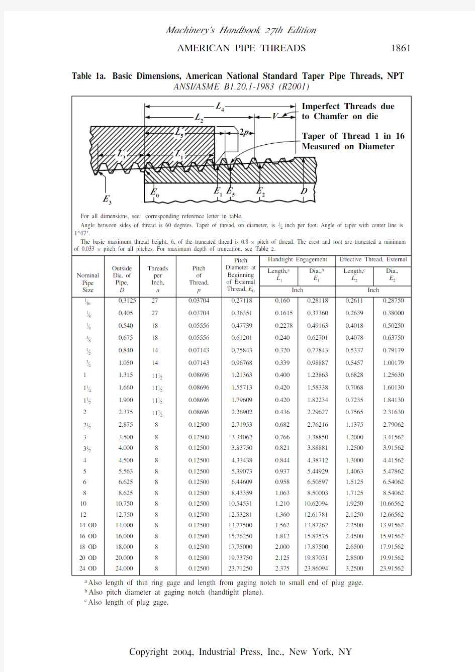
American National Standard Taper Pipe Threads.—The basic dimensions of the ANSI Standard taper pipe thread are given in Table 1a .
Form of Thread: The angle between the sides of the thread is 60 degrees when measured in an axial plane, and the line bisecting this angle is perpendicular to the axis. The depth of the truncated thread is based on factors entering into the manufacture of cutting tools and the making of tight joints and is given by the formulas in Table 1a or the data in Table 2obtained from these formulas. Although the standard shows flat surfaces at the crest and root of the thread, some rounding may occur in commercial practice, and it is intended that the pipe threads of product shall be acceptable when crest and root of the tools or chasers lie within the limits shown in Table 2.
Pitch Diameter Formulas: In the following formulas, which apply to the ANSI Standard taper pipe thread, E 0 = pitch diameter at end of pipe; E 1 = pitch diameter at the large end of the internal thread and at the gaging notch; D = outside diameter of pipe; L 1 = length of hand-tight or normal engagement between external and internal threads; L 2 = basic length of effective external taper thread; and p = pitch = 1 ÷ number of threads per inch.
Thread Length: The formula for L 2 determines the length of the effective thread and includes approximately two usable threads that are slightly imperfect at the crest. The nor-mal length of engagement, L 1, between external and internal taper threads, when assem-bled by hand, is controlled by the use of the gages.
Taper:The taper of the thread is 1 in 16, or 0.75 inch per foot, measured on the diameter and along the axis. The corresponding half-angle of taper or angle with the center line is 1degree, 47 minutes.
E 0D 0.05D 1.1+()p –=E 1E 00.0625L 1
+=L 20.80D 6.8+()p
=
AMERICAN PIPE THREADS1861 Table 1a. Basic Dimensions, American National Standard Taper Pipe Threads, NPT
ANSI/ASME B1.20.1-1983 (R2001)
a Also length of thin ring gage and length from gaging notch to small end of plug gage.
b Also pitch diameter at gaging notch (handtight plane).
c Also length of plug gage.
1862
AMERICAN PIPE THREADS
All dimensions given in inches.
Increase in diameter per thread is equal to 0.0625/n .
The basic dimensions of the ANSI Standard Taper Pipe Thread are given in inches to four or five decimal places. While this implies a greater degree of precision than is ordinarily attained, these dimensions are the basis of gage dimensions and are so expressed for the purpose of eliminating errors in computations.
Engagement Between External and Internal Taper Threads.—The normal length of engagement between external and internal taper threads when screwed together handtight is shown as L 1 in Table 1a . This length is controlled by the construction and use of the pipe thread gages. It is recognized that in special applications, such as flanges for high-pressure work, longer thread engagement is used, in which case the pitch diameter E 1 (Table 1a ) is maintained and the pitch diameter E 0 at the end of the pipe is proportionately smaller.Tolerances on Thread Elements.—The maximum allowable variation in the commer-cial product (manufacturing tolerance) is one turn large or small from the basic dimen-sions.
The permissible variations in thread elements on steel products and all pipe made of steel,wrought iron, or brass, exclusive of butt-weld pipe, are given in Table 3. This table is a
Table 1b. Basic Dimensions, American National Standard Taper Pipe Threads, NPT
ANSI/ASME B1.20.1-1983 (R2001)
Nominal Pipe Size
Wrench Makeup Length for Internal Thread Vanish Thread,(3.47 thds.),
V Overall Length External Thread,L 4
Nominal Perfect External Threads a Height of Thread,h Basic Minor Dia. at Small End of Pipe,b
K 0
Length,c
L 3Dia.,E 3Length,L 5Dia.,E 51?160.11110.264240.12850.38960.18700.282870.029630.24161?80.11110.356560.12850.39240.18980.375370.029630.33391?40.16670.466970.19280.59460.29070.495560.044440.43293?80.16670.601600.19280.60060.29670.630560.044440.56761?20.21430.745040.24780.78150.39090.782860.057140.70133?4
0.21430.954290.24780.79350.40290.992860.057140.910510.2609 1.197330.30170.98450.5089 1.245430.06957 1.144111?40.2609 1.540830.3017 1.00850.5329 1.590430.06957 1.487611?20.2609 1.779780.3017 1.02520.5496 1.830430.06957 1.726520.2609 2.252720.3017 1.05820.5826 2.305430.06957 2.199521?20.2500d 2.703910.4337 1.57120.8875 2.775000.100000 2.619530.2500d 3.325000.4337 1.63370.9500 3.400000.100000 3.240631?20.2500 3.821880.4337 1.6837 1.0000 3.900000.100000 3.737540.2500 4.318750.4337 1.7337 1.0500 4.400000.100000 4.234450.2500 5.375110.4337 1.8400 1.1563 5.463000.100000 5.290760.2500 6.430470.4337 1.9462 1.2625 6.525000.100000 6.346180.25008.417970.4337 2.1462 1.46258.525000.1000008.3336100.250010.529690.4337 2.3587 1.675010.650000.10000010.4453120.250012.517190.4337 2.5587 1.875012.650000.10000012.432814 OD 0.250013.759380.4337 2.6837 2.000013.900000.10000013.675016 OD 0.250015.746880.4337 2.8837 2.200015.900000.10000015.662518 OD 0.250017.734380.4337 3.0837 2.400017.900000.10000017.650020 OD 0.250019.721880.4337 3.2837 2.600019.900000.10000019.637524 OD
0.2500
23.69688
0.4337
3.6837
3.0000
23.90000
0.100000
23.6125
a The length L
5 from the end of the pipe determines the plane beyond which the thread form is imper-
fect at the crest. The next two threads are perfect at the root. At this plane the cone formed by the crests of the thread intersects the cylinder forming the external surface of the pipe. L 5 = L 2? 2p .b Given as information for use in selecting tap drills.
c Three threads for 2-inch size an
d smaller; two threads for larger sizes.
d Military Specification MIL—P—7105 gives th
e wrench makeup as three threads for 3 in. and smaller. The E 3 dimensions are then as follows: Size 21?2 in., 2.69609 and size 3 in., 3.31719.
英制管螺纹美制管螺纹对照表
分类:专业知识 字号:大中小 英制管螺纹美制管螺纹对照表 英制管螺纹英制管螺纹美制管螺纹 规格标准径钻孔径 规格 标准径有交牙 部之长度(最 小)中之毋螺 牙内径 标准长 度(最小)中 之毋螺牙内径 规格 钻孔径 最大最小使用纹刀时 不用纹刀 时 NPT NPS 使用绞刀时不用绞刀时 PS 1/16-28 6.50 6.632 6.490 PT 1/16-28 6.10 6.20 6.244 6.384 1/16 - 27 6.10 6.25 6.35 PS 1/8-28 8.50 8.637 8.495 PT 1/8-28 8.10 8.20 8.249 8.388 1/8 - 27 8.33 8.43 8.74 PS 1/4-19 11.40 11.549 11.341 P T 1/4-19 10.70 11.0 10.962 11.174 1/4 - 18 10.72 11.13 11.13 PS 3/8-19 15.00 15.054 14.846 P T 3/8-19 14.20 14.5 14.448 14.658 3/8 - 18 14.27 14.27 14.68 PS 1/2-14 18.50 18.773 18.489 P T 1/2-14 17.60 18.0 17.979 18.263 1/2 - 14 17.48 17.86 18.26 PS 3/4-14 24.00 24.259 23.975 P T 3/4-14 23.00 23.5 23.378 23.663 3/4 - 14 22.63 23.01 23.42 PS 1-11 30.20 30.471 30.111 P T 1-11 29.00 29.5 29.459 29.822 1 - 11-1/2 28.58 28.98 29.36
美制螺纹标准手册
螺纹一般状况 : 螺纹提供紧固件使之能作负荷之转移. 1何谓螺纹 : 所谓螺纹即为在一圆柱物体上作出突起之螺旋山状物,外螺纹适用于螺栓, 螺丝及螺桩, 内螺纹适用于螺帽及螺纹孔. 2螺纹之组成 : 主要分为三部份螺峰, 螺谷及螺腹. 螺纹部顶端称之为螺峰, 螺纹部底端称为螺谷, 二者之间称为螺腹. 三者组成一V字型之构造. 螺峰与螺谷之直线距离为螺纹高H, 螺峰与螺峰之距离为螺距P, 在UN螺纹方面H = 0.866025 x P ( 假设状况螺峰与螺谷均为V字型尖锐端 ). 3完全与不完全螺纹 : 螺纹同时具有螺峰及螺谷之完整形状时称为完全螺纹, 若螺谷或螺峰未完全成型则称为不完全螺纹. 4螺距 : 螺距P即垂直于螺丝(帽)轴螺纹上之任一点与邻近螺纹同一点之水平距离. 在UN螺纹系统中, 通常以每寸几个螺纹表示. 5大径及小径 : 在外螺纹系统中, 螺峰之外径称为大径, 螺谷之外径称为小径. 内螺纹类则正好相反, 螺峰之内径为小径, 螺谷之外径为最大径. 6螺腹 : 螺腹与轴部所成之角度称为螺腹角( Flank Angle ), 轴部双边角度相等者称为对称, 在UN螺纹系统中, 螺腹角通常为30度且对称, 故UN 螺纹之角度均为60度. 7有效径 : 理论上而言为垂直于轴而通过螺峰螺谷某点之径. 对标准螺纹而言, 此点正好位于中点. 但对非标准螺纹而言, 此点可能位于中点附近之任一点, 视实际制造状况而定.
8裕度 : 螺纹配合之裕度意味外螺纹及内螺纹均以其最大上限制造且结合时之宽裕度. 对紧固件而言, 裕度通常由外螺纹提供, 这表示外螺纹之大径, 有效径, 小径均需比基本螺纹型为小. 而内螺纹之三径则等于基本螺纹型. 9制造公差 : 公差之配合则视制造而定. 公差即上限与下限之差. 对外螺纹而言, 其公差为上限减去公差即为下限, 内螺纹则正好相反. 10螺纹长及结合深度 : 紧固件结合时, 外螺纹部之完全螺纹部之轴距为其螺纹长, 旋进内螺纹之距离为其结合深度, 螺纹长及结合深度对其强度有深切之影响. 11螺距 : 螺距一般以每寸几个螺纹表示, 常用有英制统一粗螺纹, 细螺纹及8-螺纹三种. 12螺纹强度 : 螺纹支撑转移负荷之力量决定于四个强度. 抗拉强度应力面积为螺纹支撑抵抗拉力之面积. 抗剪应力面积为计算径剪断力之面积. 防松应力面积为内螺纹及外螺纹结合互相松脱时之强度应力面积. 螺纹选择 : 螺纹选择之三要素 : 螺纹型式, 螺纹数及等级. 1螺纹型式 : IFI所承认之螺纹型式共有三种 : UN, UNR, UNJ. 它们全为60度螺纹, 不同之处仅在螺谷处. 1.1UN 螺纹 : UN螺纹型为最早之设计, 外螺纹螺谷为平底或圆底均可.
美制螺纹对照表
美制螺纹尺寸表单位:mm 外螺纹内螺纹公称 螺纹牙牙螺公差螺纹外径螺纹中径螺纹小径公差螺纹小径螺纹中径螺纹外径钻孔直径规格数高距代号Max Min Max Min Max代号Min Max Min Max Min直径 0.073(#1)1-64UNC640.2360.3972A 1.83896 1.74244 1.58242 1.53162 1.366522B 1.42494 1.58242 1.59766 1.6637 1.8542 1.397 1.8543A 1.8542 1.75768 1.59766 1.55956 1.381763B 1.42494 1.58242 1.59766 1.64592 1.8542 1.397 1-72UNF720.210.3532A 1.83896 1.75006 1.61036 1.5621 1.419862B 1.4732 1.6129 1.6256 1.6891 1.8542 1.5113 3A 1.8542 1.7653 1.6256 1.59004 1.43513B 1.4732 1.6129 1.6256 1.67386 1.8542 1.5113 0.086(#2)2-56UNC560.2710.4542A 2.16916 2.06502 1.87452 1.82118 1.630682B 1.69418 1.87198 1.88976 1.96088 2.1844 1.7018 2.1843A 2.1844 2.08026 1.88976 1.84912 1.645923B 1.69418 1.87198 1.88976 1.9431 2.1844 1.7018 2-64UNF640.2360.3972A 2.16916 2.07264 1.91262 1.86182 1.696722B 1.75514 1.91262 1.92786 1.99644 2.1844 1.778 3A 2.1844 2.08788 1.92786 1.88976 1.711963B 1.75514 1.91262 1.92786 1.97866 2.1844 1.778 0.099(3#))3-48UNC480.3150.5292A 2.49682 2.38252 2.15392 2.0955 1.864362B 1.94056 2.1463 2.1717 2.2479 2.5146 1.9939 2.5153A 2.5146 2.4003 2.1717 2.12852 1.882143B 1.94056 2.1463 2.1717 2.22758 2.5146 1.9939 3-56UNF560.2710.4542A 2.49682 2.39268 2.20218 2.1463 1.958342B 2.02438 2.1971 2.21996 2.29108 2.5146 2.0574 3A 2.5146 2.41046 2.21996 2.17932 1.976123B 2.02438 2.1971 2.21996 2.2733 2.5146 2.0574 0.112(#4)4-40UNC400.3780.6352A 2.82448 2.69494 2.413 2.3495 2.067562B 2.15646 2.38506 2.43332 2.51714 2.8448 2.1844 2.8453A 2.8448 2.71526 2.43332 2.38506 2.087883B 2.15646 2.38506 2.43332 2.49428 2.8448 2.1844 4-48UNF480.3150.5292A 2.82702 2.71272 2.48412 2.42316 2.194562B 2.27076 2.45872 2.5019 2.58064 2.8448 2.2606 3A 2.8448 2.7305 2.5019 2.45618 2.212343B 2.27076 2.45872 2.5019 2.56032 2.8448 2.2606 0.125(#5)5-40UNC400.3780.6352A 3.15468 3.02514 2.7432 2.67716 2.397762B 2.48666 2.69748 2.76352 2.84734 3.175 2.5273 3.1753A 3.175 3.04546 2.76352 2.71526 2.418083B 2.48666 2.69748 2.76352 2.82702 3.175 2.5273 5-44UNF440.3440.5772A 3.15722 3.0353 2.7813 2.7178 2.468882B 2.55016 2.74066 2.79908 2.88036 3.175 2.5781 3A 3.175 3.05308 2.79908 2.75082 2.486663B 2.55016 2.74066 2.54508 2.86004 3.175 2.5781 0.138(#6)6-32UNC320.4720.7942A 3.48488 3.33248 2.96926 2.89814 2.542B 2.6416 2.8956 2.98958 3.08356 3.5052 2.7051 3.5053A 3.5052 3.3528 2.98958 2.93624 2.560323B 2.6416 2.8956 2.98958 3.05816 3.5052 2.7051 6-40UNF400.3780.6352A 3.48488 3.35534 3.0734 3.00736 2.727962B 2.8194 3.0226 3.09372 3.18008 3.5052 2.8702 3A 3.5052 3.37566 3.09372 3.04292 2.748283B 2.8194 3.01244 3.09372 3.15722 3.5052 2.8702 0.164(#8)8-32UNC320.4720.7842A 4.14274 3.99034 3.62712 3.55346 3.197862B 3.302 3.5306 3.64998 3.7465 4.1656 3.4544
美制螺纹标准手册
YESWIN螺纹教材螺纹一般状况: 螺纹提供紧固件使之能作负荷之转移. 1 何谓螺纹 : 所谓螺纹即为在一圆柱物体上作出突起之螺旋山状物,外螺纹适用于螺栓, 螺丝及螺桩, 内螺纹适用于螺帽及螺纹孔. 2 螺纹之组成: 主要分为三部份螺峰, 螺谷及螺腹. 螺纹部顶端称之为螺峰, 螺纹部底端称为螺谷, 二者之间称为螺腹. 三者组成一V字型之构造. 螺峰与螺谷之直线距离为螺纹高H, 螺峰与螺峰之距离为螺距P, 在UN螺纹方面H = 0.866025 x P ( 假设状况螺峰与螺谷均为V字型尖锐端 ). 完全与不完全螺纹 : 螺纹同时具有螺峰及螺谷之完整形状时称为完全螺纹, 若螺谷或螺3 峰未完全成型则称为不完全螺纹. 螺距 : 螺距P 即垂直于螺丝(帽)轴螺纹上之任一点与邻近螺纹同一点之水平距离. 在UN4 螺纹系统中, 通常以每寸几个螺纹表示. 大径及小径 : 在外螺纹系统中, 螺峰之外径称为大径, 螺谷之外径称为小径. 内螺纹类5 则正好相反, 螺峰之内径为小径, 螺谷之外径为最大径. 螺腹: 螺腹与轴部所成之角度称为螺腹角( Flank Angle ), 轴部双边角度相等者称为对称, 6 在UN螺纹系统中, 螺腹角通常为30度且对称, 故UN螺纹之角度均为60度. 7 有效径 : 理论上而言为垂直于轴而通过螺峰螺谷
某点之径. 对标准螺纹而言, 此点正好位于中点. 但对非标准螺纹而言, 此点可能位于中点附近之任一点, 视实际制造状况而定. 8 裕度 : 螺纹配合之裕度意味外螺纹及内螺纹均以其最大上限制造且结合时之宽裕度. 对紧固件而言, 裕度通常由外螺纹提供, 这表示外螺纹之大径, 有效径, 小径均需比基本螺纹型为小. 而内螺纹之三径则等于基本螺纹型. 9 制造公差 : 公差之配合则视制造而定. 公差即上限与下限之差. 对外螺纹而言, 其公差为上限减去公差即为下限, 内螺纹则正好相反. 10 螺纹长及结合深度: 紧固件结合时, 外螺纹部之完全螺纹部之轴距为其螺纹长, 旋进内螺纹之距离为其结合深度, 螺纹长及结合深度对其强度有深切之影响. 11 螺距: 螺距一般以每寸几个螺纹表示, 常用有英制统一粗螺纹, 细螺纹及8-螺纹三种. 12 螺纹强度 : 螺纹支撑转移负荷之力量决定于四个强度. 抗拉强度应力面积为螺纹支撑抵抗拉力之面积. 抗剪应力面积为计算径剪断力之面积. 防松应力面积为内螺纹及外螺纹结合互相松脱时之强度应力面积. 螺纹选择 :螺纹选择之三要素: 螺纹型式, 螺纹数及等级. 1 螺纹型式: IFI所承认之螺纹型式共有三种: UN, UNR, UNJ. 它们全为60度螺纹, 不同之处仅在螺谷处. 1.1 UN 螺纹: UN螺纹型为最早之设计, 外螺纹螺谷为平底或圆底均
英、美制螺纹标准直径、螺距参照表
英、美制标准螺纹直径、螺距参照系列表 UNC-粗牙UNF-细牙 标准国别美制ANSI BI.1-1982英国标准BS84-1956 规格直径UNC牙数/寸UNF牙数/寸BSW牙数/寸BSF牙数/寸0# 1.52 / 80 / / 1# 1.85 64 72 / / 2# 2.18 56 64 / / 3# 2.51 48 56 / / 4# 2.84 40 48 / / 5#,(1/8”) 3.18 40 44 40 / 6# 3.51 32 40 / / 8# 4.17 32 36 / / 10#(3/16”) 4.83 24 32 24 32 12#(7/32”) 5.49 24 28 / 28 1/4” 6.35 20 28 20 26 5/16”7.94 18 24 18 22 3/8”9.53 16 20 16 20 7/16”11.11 14 20 14 18 1/2”12.70 13 18 12 16 9/16”14.29 12 18 12 16 5/8”15.88 11 / 11 14 11/16”17.46 / 16 11 14 3/4”19.05 10 / 10 12 13/16”20.64 / 14 / / 7/8”22.23 9 / 9 11 15/16”23.81 / 12 / / 1”25.40 8 12 8 10 1 1/8”28.58 7 1 2 7 9
1 1/4”31.75 7 1 2 7 9 1 3/8”34.93 6 1 2 / 8 1 1/2" 38.10 6 1 2 6 8 1 5/8”41.28 / / / 8 1 3/4”44.45 5 / 5 7 1 7/8”47.63 / / / 2”50.80 4.5 / 5 7 螺纹站孔的直径的计算 一般按下列公式: 1.攻公制螺纹:螺距t<1毫米,dz=d-t t>1毫米,dz=d-(1.04~1.06)t 式中t——螺距(毫米) dz——攻丝前钻孔直径(毫米) d——螺纹公称直径(毫米) 2.攻英制螺纹: 螺纹公称直径铸铁与青铜钢与黄铜 3/16"~5/8" dz=25(d-1/n) dz=25(d-1/n)+0.1 3/4"~11/2" dz=25(d-1/n) dz=25(d-1/n) +0.2 式中dz——攻丝前钻孔直径(毫米) d——螺纹公称直径(英寸)n——每英寸牙数
公制,英制,美制螺纹尺寸对照表
螺纹简介:
1.1螺纹的起源 一般认为,阿基米德(公元前287-212年)是首先将螺纹用于工业目的,即将低处的水移到高处的一种工具。1659年法国人贝兹逊发明螺纹切割机;其后,经过英国的威阿特、亨利?莫斯列,到其子弟约瑟夫?惠氏于1841年才统一原本混乱的螺纹,促进螺纹制品的全球普及;因此,惠氏螺纹也随英国工业的发达而广泛传播世界。 美制螺纹依据塞勒氏螺纹(Seller's thread)而问世于1924年;二次世界大战中,美国、英国、加拿大三国协定发展成统一制螺纹Unified thread。随着国际交流的频繁,1947年成立的ISO国际标准化组织(International standard organization)成为推动国际标准化的重要力量。 1.2螺纹概述 按用途分类,可分为紧固螺纹、密封螺纹、传动螺纹、管螺纹、专用螺纹。 1.3螺纹的分类 A、公制螺纹 表示螺纹的记号为M,公称直径d或D与螺距P是以mm毫米来标识,螺纹牙尖角为60度。这是我国GB标准所规定使用的螺纹,也是常见到的。 B、英美制统一螺纹 表示螺纹的记号为U,公称直径d或D为英寸,螺距是以每英寸(25.4mm)的牙树来标识,螺纹牙尖角为60度。这是通俗成为美制规格的螺纹。 C、惠氏螺纹 表示螺纹的记号为W,螺纹直径为英寸,螺距以每英寸(25.4mm)的牙树来标识,螺纹牙尖角为55度。这是英国采用的标准,牙尖角有点特殊的螺纹。 D、管用螺纹 主要指英国BSP螺纹系统,用在管接头,分为推拔螺纹(记号为PT)和平和螺纹(记号为PS),牙尖角为55度,螺距以每英寸(25.4mm)的牙树来标识;公称方法依据所配的钢管的公称方法(英寸),因此,实际的螺纹外径与公称直径不同。 E、自行车用螺纹
美制螺纹标准对照表
美制螺纹标准对照表 美制外螺纹(2A)常用规格极限尺寸表(粗牙) 公称尺寸和每英寸牙 数螺纹系 列代号 大径极限中径极限 小径max 螺胚直径最小最大最小最大最小最大 8-32 UNC 0.1571 0.1631 0.1399 0.1428 0.1248 3.58 3.61 (0.164-32) 3.9903 4.1427 3.5535 3.6271 3.1699 10-24 0.1818 0.1890 0.1586 0.1619 0.1379 4.07 4.10 (0.190-24) 4.6177 4.8006 4.0284 4.1123 3.5027 12-24 0.2078 0.2150 0.1845 0.1879 0.1639 4.72 4.75 (0.216-24) 5.2781 5.4610 4.6863 4.7727 4.1631 1/4-20 0.2408 0.2489 0.2127 0.2164 0.1876 5.45 5.48 (0.250-20) 6.1163 6.3221 5.4026 5.4966 4.7650 5/16-18 0.3026 0.3113 0.2712 0.2752 0.2431 6.94 6.98 (0.3175-18) 7.6860 7.9070 6.8885 6.9901 6.1747 3/8-16 0.3643 0.3737 0.3287 0.3331 0.2970 8.40 8.44 (0.375-16) 9.2532 9.4920 8.3490 8.4607 7.5438 7/16-14 0.4258 0.4361 0.3850 0.3897 0.3485 9.83 9.87 (0.4375-14) 10.8153 11.0769 9.7790 9.8984 8.8519 1/2-13 0.4876 0.4985 0.4435 0.4485 0.4041 11.34 11.38 (0.50-13) 12.3850 12.6619 11.2649 11.3919 10.2641 9/16-12 0.5495 0.5609 0.5016 0.5068 0.4587 12.80 12.84 (0.5625-12) 13.9573 14.2469 12.7406 12.8727 11.6510 5/8-11 0.6113 0.6234 0.5589 0.5644 0.5119 14.27 14.32 (0.625-11) 15.5270 15.8344 14.1961 14.3358 13.0023 3/4-10 0.7353 0.7482 0.6773 0.6832 0.6255 17.28 17.33 (0.750-10) 18.6766 19.0043 17.2034 17.3533 15.8877 7/8-9 0.8592 0.8731 0.7946 0.8009 0.7368 20.27 20.32 (0.875-9) 21.8237 22.1767 20.1828 20.3429 18.7147 1"-8 0.9830 0.9980 0.9100 0.9168 0.8446 23.22 23.27 (1.000-8) 24.9682 25.3492 23.1140 23.2867 21.4528 1.螺胚直径指滚丝前的尺寸,数值为依经验公式计算而得,在实践中需验证。 2.标记示例:10-24UNC-2A(或0.190-24UNC-2A)、3/8-16UNC-2A(或0.375-16UNC-2A) (注:表中上行斜体数值单位为英寸,下行为毫米) 美制外螺纹(2A)常用规格极限尺寸表(细牙) 公称尺寸和每英寸牙数螺纹系 列代号 大径极限中径极限 小径max 螺胚直径最小最大最小最大最小最大 8-36 UNF 0.1577 0.1632 0.1424 0.1452 0.1291 3.65 3.67 (0.164-36) 4.0056 4.1453 3.6170 3.6881 3.2791 10-32 0.1831 0.1891 0.1658 0.1688 0.1508 4.24 4.27 (0.190-32) 4.6507 4.8031 4.2113 4.2875 3.8303 12-28 0.2085 0.2150 0.1886 0.1918 0.1712 4.82 4.85 (0.216-28) 5.2959 5.4610 4.7904 4.8717 4.3485
公制美制英制螺纹对照表
公制/美制/英制螺纹对照表 A型美制螺纹(UNF)常用规格 外螺纹内螺纹 -4 9/16"-19牙 14.28 13.08 -6 11/16''-16 17.46 16.1 -8 13/16''-16 20.64 19.28 -10 1''-14 25.40 23.57 -12 1(3/16)''-12 30.00 28.32 -16 1(7/16)''-12 36.51 34.67 -20 1(11/16)''-12 42.86 41.02 C型JIC37度美制UNF螺纹常用规格-4 7/16”-20 11.11 10.03 -5 1/2”-20 12.70 11.32 -6 9/16”-18 14.28 13.08 -8 3/4”-16 19.00 17.68 -10 7/8”-14 22.22 20.68 -12 1(1/16)"-12 26.98 25.15 -16 1(5/16)"-12 33.33 31.5 -20 1(5/8)"-12 41.28 39.44 -24 1(7/8)"-12 47.62 45.8 -32 2(1/2)"-12 63.5 61.67 英制圆柱管螺纹(BSPP)常用规格 -4 1/4”-19 13.157 11.55 -6 3/8”-19 16.662 14.95 -8 1/2”-14 20.955 18.63 -12 3/4”-14 26.441 24.11 -16 1”-11 33.249 30.29 -20 1(1/4)''-11 41.91 38.95 英制圆锥管螺纹(BSPT)常用规格基面大径基准距离 1/4”-19 13.157 6 3/8”-19 16.662 6.4 1/2”-14 20.955 8.2 3/4”-14 26.441 9.5 1”-11 33.249 10.4 1(1/4)''-11 41.91 12.7
美制螺纹最齐全大全
美制外螺纹(2A)常用规格极限尺寸表(粗牙) 公称尺寸和每英寸牙数螺纹系 列代号 大径极限中径极限 小径max 螺胚直径最小最大最小最大最小最大 8-32 UNC 0.1571 0.1631 0.1399 0.1428 0.1248 3.58 3.61 (0.164-32) 3.9903 4.1427 3.5535 3.6271 3.1699 10-24 0.1818 0.1890 0.1586 0.1619 0.1379 4.07 4.10 (0.190-24) 4.6177 4.8006 4.0284 4.1123 3.5027 12-24 0.2078 0.2150 0.1845 0.1879 0.1639 4.72 4.75 (0.216-24) 5.2781 5.4610 4.6863 4.7727 4.1631 1/4-20 0.2408 0.2489 0.2127 0.2164 0.1876 5.45 5.48 (0.250-20) 6.1163 6.3221 5.4026 5.4966 4.7650 5/16-18 0.3026 0.3113 0.2712 0.2752 0.2431 6.94 6.98 (0.3175-18) 7.6860 7.9070 6.8885 6.9901 6.1747 3/8-16 0.3643 0.3737 0.3287 0.3331 0.2970 8.40 8.44 (0.375-16) 9.2532 9.4920 8.3490 8.4607 7.5438 7/16-14 0.4258 0.4361 0.3850 0.3897 0.3485 9.83 9.87 (0.4375-14) 10.8153 11.0769 9.7790 9.8984 8.8519 1/2-13 0.4876 0.4985 0.4435 0.4485 0.4041 11.34 11.38 (0.50-13) 12.3850 12.6619 11.2649 11.3919 10.2641 9/16-12 0.5495 0.5609 0.5016 0.5068 0.4587 12.80 12.84 (0.5625-12) 13.9573 14.2469 12.7406 12.8727 11.6510 5/8-11 0.6113 0.6234 0.5589 0.5644 0.5119 14.27 14.32 (0.625-11) 15.5270 15.8344 14.1961 14.3358 13.0023 3/4-10 0.7353 0.7482 0.6773 0.6832 0.6255 17.28 17.33 (0.750-10) 18.6766 19.0043 17.2034 17.3533 15.8877 7/8-9 0.8592 0.8731 0.7946 0.8009 0.7368 20.27 20.32 (0.875-9) 21.8237 22.1767 20.1828 20.3429 18.7147 1"-8 0.9830 0.9980 0.9100 0.9168 0.8446 23.22 23.27 (1.000-8) 24.9682 25.3492 23.1140 23.2867 21.4528 1.螺胚直径指滚丝前的尺寸,数值为依经验公式计算而得,在实践中需验证。 2.标记示例:10-24UNC-2A(或0.190-24UNC-2A)、3/8-16UNC-2A(或0.375-16UNC-2A) (注:表中上行斜体数值单位为英寸,下行为毫米) 美制外螺纹(2A)常用规格极限尺寸表(细牙) 公称尺寸和每英寸牙数螺纹系 列代号 大径极限中径极限 小径max 螺胚直径最小最大最小最大最小最大 8-36 UNF 0.1577 0.1632 0.1424 0.1452 0.1291 3.65 3.67
统一螺纹标准(美制螺纹)
统一螺纹标准(美制螺纹标准) 统一螺纹标准(UTS)规定了一种标准螺纹形式和其他一系列数据,包括公差、容差和名称,通常多用于美国和加拿大。它和世界其他地方常用的ISO公制螺纹相同,有着60°的牙型角,只是UTS螺纹的主要尺寸(外径和螺距)以英寸为单位,用分数表示,而不是以毫米为单位的整数值。UTS目前由美国机械工程师协会/美国国家标准化组织(ASME/ANSI)管理控制。 基本齿廓 在本系列螺纹中,每个螺纹由大径Dmaj和螺距P规定。UTS螺纹包括一个对称的V形螺纹。在螺纹轴线 的平面上,V形两边形成60° 的夹角,V形高度为H,其最上 的0.125和最下的0.25被切 掉。 螺距P指两个螺纹顶端之 间的距离。UTS螺纹为单线螺 纹,螺距等于导程(螺纹每 360°的轴向距离)。UTS螺纹通 常不用螺距这一参数,而用每 英寸的牙数(TPI),它与螺距 互为倒数。高度H和螺距P关系如下: 在外螺纹中(如螺栓),大直径Dmaj和小直径Dmin规定了螺纹的最大尺寸。这也就是说,外螺纹直径最大为Dmaj,但最小直径可小于小径Dmin。相反,在内螺纹中(如螺母),大径和小径为最小尺寸,因此螺纹最小尺寸为Dmin,但最大尺寸可大于Dmaj。 小径Dmin和有效中径Dp是通过大径和螺距得来的,见下式: 名称 UTS螺纹的标准名称由一个表示螺纹公称直径(大径)的数字,后跟每英寸的牙数表示。对直径小于1/4英寸的,标准中规定用一个整数表示。所有其他直
径均以英寸表示。 这组数字后可跟字母UNC、UNF或UNEF,分别表示“粗螺纹”、“细螺纹”或“超细螺纹”,或者也可跟公差级别。 例: 6-32 UNC 2B (大径:0.1380英寸,螺距:32牙/英寸) 常用尺寸 这些数字大致遵循一个对数级数,每增加一个螺纹尺寸,其螺纹抗拉强度约增加一倍。 规格大于等于0#的螺纹,可用下列公式计算其大径:大径=螺纹#×0.013"
美制螺纹标准
美制螺纹 美制标准螺纹(也称统一制螺纹)量规用于检测螺纹的内外牙,螺纹牙形角60度,由外径、每英寸牙数、精度组合表示,如1/4-20UNC-2B,表示1/4英寸外径、每英寸20牙、2B精度内螺纹塞规,若是左旋旋向,应加LH表示。美制内螺纹默认精度为2B,3B紧密级亦可提供,此外美制外螺纹的默认精度为2A,紧密级精度为3A,订货时注明精度,不提供精度按默认精度提供。美制螺纹系列众多,美制粗牙(UNC)、美制细牙(UNF)、美制特细牙(UNEF)、美制不变螺距螺纹(UN)、美制特殊螺纹(UNS)。还有一些美制牙将另外描叙。第二次世界大战中,盟军的武器和装备所使用的螺纹主要有两种:一种是英国的惠氏螺纹(BSW、BSF);另一种是美国国家螺纹(UNC、UNF、UNEF、UN、UNS);由于两种螺纹的标准不统一,给盟军造成了严重的经济损失和人员伤亡。二战结束以后,美国、英国和加拿大等盟国马上制定了统一的螺纹标准,由于当时美国的经济实力和军事实力在盟军中占主导地位,统一制螺纹主要是依据美国国家螺纹标准制定的,因此,在紧固螺纹领域,统一制螺纹开始挤占英国惠氏螺纹的使用市场,惠氏螺纹的圆弧牙顶和牙底牙型,叫英国吃了苦果;另外,澳大利亚、马来西亚、印度尼西亚、阿根廷、智利、比利时、匈牙利、意大利、瑞典、捷克等各国家也制定了惠氏螺纹国家标准。现在世界各国使用惠氏螺纹(BSW、BSF)的国家在不断减少,取而代之的是统一制螺纹(UNC、UNF、UNEF、UN、UNS)。美制螺纹(UNC、UNF、UNEF、UN、UNS)相关规格:NO:0-80UNF、NO:1-64UNC、NO:2-56UNC、NO:3-48UNC、NO:4-40UNC、NO:4-48UNF、NO:5-40UNC、NO:6-32UNC、NO:6-40UNF、NO:8-32UNC、NO:8-36UNC、NO:10-24UNC、NO:10-32UNF、NO:10-40UNS、NO:12-24UNC、NO:12-28UNF、NO:12-36UNS、1/4-20UNC、1/4-24UNS、1/4-28UNF、1/4-32UNEF、5/16-18UNC、5/16-20UN、5/16-24UNF、5/16-27UNS、5/16-32UNEF、3/8-16UNC、3/8-20UN、3/8-24UNF、3/8-32UNEF、7/16-14UNC、7/16-20UNF、 7/16-24UNS、7/16-28UNEF、1/2-12UNS、1/2-13UNC、1/2-16UN、1/2-20UNF、1/2-28UNEF、9/16-12UNC、9/16-18UNF、9/16-24UNEF、5/8-11UNC、5/8-18UNF、5/8-24UNEF、3/4-10UNC、3/4-16UNF、 3/4-20UNEF、3/4-24UNS、7/8-14UNF、7/8-20UNEF、7/8-24UNS、15/16-28UN、1"-8UNC、1"-12UNF、1"-20UNEF、1-1/8-12UNF、 1-1/8-16UN、1-1/4-7UNC、1-1/4-12UNF、1-1/2-6UNC等等。
公制美制螺纹牙距表
1,公制螺纹牙距表 公称直径牙距mm 毫米粗牙细牙 M1 0.25 0.2 M1.2 0.25 0.2 M1.6 0.35 0.2 M2 0.4 0.25 M2.5 0.45 0.35 M3 0.5 0.35 M4 0.7 0.5 M5 0.8 0.5 M6 1 0.75 M8 1.25 1 M10 1.5 1.25 M12 1.75 1.25 M14 2 1.5 M16 2 1.5 M18 2.5 1.5 M20 2.5 1.5 M22 2.5 1.5 M24 3 2 M27 3 2 M30 3.5 2 (M33) 3.5 2 M36 4 3 (M39) 4 3 M42 4.5 3 (M45) 4.5 3 M48 5 3 2,美制统一标准螺纹牙数表 公称直径直径尺寸牙距 in mm 粗牙细牙 0# 0.06 1.524 - 80 1# 0.073 1.854 64 72 2# 0.086 2.184 56 64 3# 0.099 2.515 48 56 4# 0.112 2.845 40 48 5# 0.125 3.175 40 44 6# 0.138 3.505 32 40 8# 0.164 4.166 32 36 10# 0.19 4.826 24 32 12# 0.216 5.486 24 28
1/4" 0.25 6.35 20 28 5/16" 0.3125 7.938 18 24 3/8" 0.375 9.525 16 24 7/16" 0.4375 11.113 14 20 1/2" 0.5 12.7 13 20 9/16" 0.5625 14.288 12 18 5/8" 0.625 15.875 11 18 3/4" 0.75 19.05 10 16 7/8" 0.875 22.225 9 14 1" 1 25.4 8 12 1-1/8" 1.125 28.575 7 12 1-1/4" 1.25 31.75 7 12 1-3/8" 1.375 34.925 6 12 1-1/2" 1.5 38.1 6 12 1-3/4" 1.75 44.45 5 - 2" 2 50.8 4.5 – 6-32是每英寸牙数(在25.4mm长度上的牙数) 螺距=25.4/每英寸牙数 例如:6牙 螺距=25.4/6=4.2333
美制螺纹标准对照表
最小最大最小最大最小最大 8‐320.15710.16310.13990.14280.1248(0.164‐32) 3.9903 4.1427 3.5535 3.6271 3.1699 10‐240.18180.1890.15860.16190.1379(0.190‐24) 4.6177 4.8006 4.0284 4.1123 3.5027 12‐240.20780.2150.18450.18790.1639(0.216‐24) 5.2781 5.461 4.6863 4.7727 4.1631 1/4‐200.24080.24890.21270.21640.1876(0.250‐20) 6.1163 6.3221 5.4026 5.4966 4.765 5/16‐180.30260.31130.27120.27520.2431(0.3175‐18)7.6867.907 6.8885 6.9901 6.1747 3/8‐160.36430.37370.32870.33310.297(0.375‐16)9.25329.4928.3498.46077.5438 7/16‐140.42580.43610.3850.38970.3485(0.4375‐14)10.815311.07699.7799.89848.8519 1/2‐130.48760.49850.44350.44850.4041(0.50‐13)12.38512.661911.264911.391910.26419/16/20120.54950.56090.50160.50680.4587(0.5625‐12)13.957314.246912.740612.872711.651 5/8‐110.61130.62340.55890.56440.5119(0.625‐11)15.52715.834414.196114.335813.0023 3/4‐100.73530.74820.67730.68320.6255(0.750‐10)18.676619.004317.203417.353315.8877 7/8‐90.85920.87310.79460.80090.7368(0.875‐9)21.823722.176720.182820.342918.71471"‐80.9830.9980.910.91680.8446(1.000‐8) 24.9682 25.3492 23.114 23.2867 21.4528 美制外螺纹(2A )常用规格极限尺寸表(粗牙) 公称尺寸和每英寸牙数螺纹系列代号大径极限中径极限小径max 螺胚直径4.14.72 4.755.45 5.486.94 6.988.48.449.839.8711.3411.3812.812.8414.2714.3217.2817.3320.2720.3223.22 23.27 1.螺胚直径指滚丝前的尺寸,数值为依经验公式计算而得,在实践中需验证。 2.标记示例:10‐24UNC ‐2A(或0.190‐24UNC ‐2A)、3/8‐16UNC ‐2A(或0.375‐16UNC ‐2A)UNC 3.58 3.61 4.07(注:表中上行斜体数值单位为英寸,下行为毫米) 美制螺纹标准对照表
国标,英标,美标螺纹规格表
G、RP(内) PF(日) 0.6403t 圆柱管螺纹(55°)上部H/6 下部H/6 削平ZG、R(外)、RC(内)、PT(外)、NPT(内)圆锥管螺纹(55°)上部H/6 下部H/6 削平Z 0.8t 布锥管螺纹(60°)上部0.033t下部0.033t BSP、BSPP=G 英制管螺纹(55°)上部H/6 下部H/6 削平UNC(粗)、UNF(细) 美制螺纹(60°) 上部H/8 下部H/4 削平BSW(粗)、BSF(细) 惠制螺纹(55°) 上部H/6 下部H/6 削平注意:美制与惠制螺纹均为紧固件类螺纹 圆柱管螺纹公称直径为管子内径尺寸。 公制螺纹加工表 内螺纹小径:D1=D-1.082532t 外螺纹小径:d1=d-1.082532t 公制螺纹 粗牙(60°)公制螺纹 细牙(60°) 注意:底孔尺寸均为加工螺纹孔时专用尺寸。 深度尺寸均为加工螺纹孔时孔深度尺寸。 (规定为15倍螺距)
G 英制圆柱管螺纹(55°)加工一览表 小径:d1=d-1.2807t ZG 英制锥管螺纹(55°)加工一览表 小径:d=d-1.2807t 注意:底孔尺寸均为加工螺纹孔时专用尺寸。 深度尺寸均为加工螺纹孔时孔深度尺寸。 (规定为15倍螺距)
Z 圆锥管螺纹(布锥管螺纹) (60°)小径:d1=d-1.6t 美制螺纹(UNC、UNF)参数表(60°) 底孔尺寸均为加工螺纹孔时专用尺寸。 深度尺寸均为加工螺纹孔时孔深度尺寸。 (规定为15倍螺距)
惠氏螺纹(BSW、BSF)参数表(55°)小径:d1=d-1.280655t 注意:in为英寸符号,一英寸等于25.4毫米。 底孔尺寸均为加工螺纹孔时专用尺寸。 深度尺寸均为加工螺纹孔时光孔深度尺寸。 (规定为15倍螺距) 惠氏螺纹为紧固件螺纹。公称直径为螺纹大径。
美制NPT螺纹标准
1860 AMERICAN PIPE THREADS PIPE AND HOSE THREADS The types of threads used on pipe and pipe fittings may be classed according to their intended use: 1) threads that when assembled with a sealer will produce a pressure-tight joint; 2) threads that when assembled without a sealer will produce a pressure-tight joint;3) threads that provide free- and loose-fitting mechanical joints without pressure tight-ness; and 4) threads that produce rigid mechanical joints without pressure tightness. American National Standard Pipe Threads American National Standard pipe threads described in the following paragraphs provide taper and straight pipe threads for use in various combinations and with certain modifica-tions to meet these specific needs. Thread Designation and Notation.—American National Standard Pipe Threads are des-ignated by specifying in sequence the nominal size, number of threads per inch, and the symbols for the thread series and form, as: 3?8—18 NPT. The symbol designations are as follows: NPT—American National Standard Taper Pipe Thread; NPTR—American National Standard Taper Pipe Thread for Railing Joints; NPSC—American National Stan-dard Straight Pipe Thread for Couplings; NPSM—American National Standard Straight Pipe Thread for Free-fitting Mechanical Joints; NPSL—American National Standard Straight Pipe Thread for Loose-fitting Mechanical Joints with Locknuts; and NPSH—American National Standard Straight Pipe Thread for Hose Couplings. American National Standard Taper Pipe Threads.—The basic dimensions of the ANSI Standard taper pipe thread are given in Table 1a . Form of Thread: The angle between the sides of the thread is 60 degrees when measured in an axial plane, and the line bisecting this angle is perpendicular to the axis. The depth of the truncated thread is based on factors entering into the manufacture of cutting tools and the making of tight joints and is given by the formulas in Table 1a or the data in Table 2obtained from these formulas. Although the standard shows flat surfaces at the crest and root of the thread, some rounding may occur in commercial practice, and it is intended that the pipe threads of product shall be acceptable when crest and root of the tools or chasers lie within the limits shown in Table 2. Pitch Diameter Formulas: In the following formulas, which apply to the ANSI Standard taper pipe thread, E 0 = pitch diameter at end of pipe; E 1 = pitch diameter at the large end of the internal thread and at the gaging notch; D = outside diameter of pipe; L 1 = length of hand-tight or normal engagement between external and internal threads; L 2 = basic length of effective external taper thread; and p = pitch = 1 ÷ number of threads per inch. Thread Length: The formula for L 2 determines the length of the effective thread and includes approximately two usable threads that are slightly imperfect at the crest. The nor-mal length of engagement, L 1, between external and internal taper threads, when assem-bled by hand, is controlled by the use of the gages. Taper:The taper of the thread is 1 in 16, or 0.75 inch per foot, measured on the diameter and along the axis. The corresponding half-angle of taper or angle with the center line is 1degree, 47 minutes. E 0D 0.05D 1.1+()p –=E 1E 00.0625L 1 +=L 20.80D 6.8+()p =