卡乐加湿器厂家说明书完整版
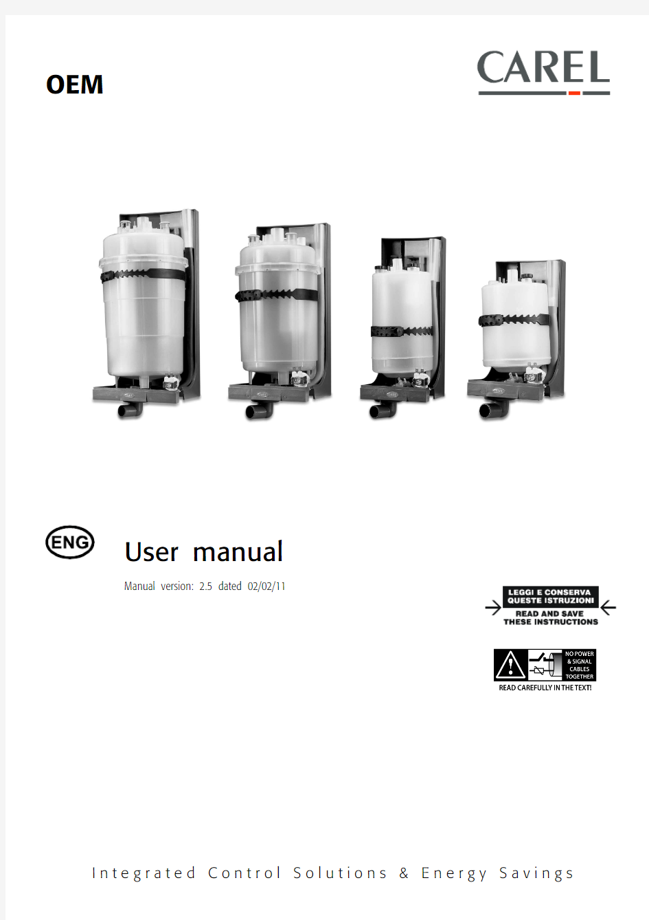

OEM
User manual
Manual version: 2.5 dated 02/02/11
I n t e g r a t e d C o n t r o l S o l u t i o n s&E n e r g y S a v i n g s
We wish to save you time and money!We wish to save you time and money!
We can assure you that th We can assure you that the thorough reading of this manual will guarantee correct installation and safe e thorough reading of this manual will guarantee correct installation and safe
use of the product https://www.360docs.net/doc/9d13199970.html,e of the product described.
WARNING: separate as much as possible the probe and digital input signal cables from the cables
carrying inductive loads and power cables to carrying inductive loads and power cables to avoid possible electromagnetic disturbance. Never
run power cables (including the electrical panel wiring) and signal cables in the same conduits run power cables (including the electrical panel wiring) and signal cables in the same conduits.
IMPORTANT WARNINGS
BEFORE INSTALLING OR HANDLING THE APPLIANCE, PLEASE CAREFULLY READ AND FOLLOW THE INSTRUCTIONS AND SAFETY REGULATIONS CONTAINED IN THIS MANUAL AND INDICATED ON THE LABELS ATTACHED TO THE UNIT.
REGULATIONS CONTAINED IN THIS MANUAL AND INDICATED ON THE LABELS ATTACHED TO THE UNIT.
INSTRUCTION SHEET +050003765 OF THE CP* CONTROL BOARD IS AN INTEGRAL PART OF THIS MANUAL!INSTRUCTION SHEET +050003765 OF THE CP* CONTROL BOARD IS AN INTEGRAL PART OF THIS MANUAL!
CAREFULLY KEEP INSTRUCTION SHEET +050003765 TOGETHER CAREFULLY KEEP INSTRUCTION SHEET +050003765 TOGETHER WITH THIS MANUAL!WITH THIS MANUAL!
WITH THIS MANUAL!
This humidifier produces non-pressurised steam by means of electrodes immersed in the water contained in the cylinder-boiler (hereafter referred to as the cylinder cylinder
cylinder). The electrodes pass electric current through water, which, acting as electrical resistance, heats up. The steam produced is used to humidify rooms or industrial processes, by means of special distributors.
As the quality of the water in use affects the evaporation process, the appliance may be supplied with untreated water a a s long as it is drinkable and not demineralised
not demineralised (refer to supply water requirements); the evaporated water is automatically topped up using of a fill valve. This appliance has been designed exclusively to humidify rooms directly or in ducts through a distribution system. Installation, use and maintenance shall be carried out according to the instructions contained in this manual.
The environmental conditions and the power supply voltage must comply with the specified values.
The environmental conditions and the power supply voltage must comply with the specified values. Any other use and modification t Any other use and modification to the appliance not expressly authorised by the manufacturer shall be considered as improper.o the appliance not expressly authorised by the manufacturer shall be considered as improper.o the appliance not expressly authorised by the manufacturer shall be considered as improper. Liability for injuries or damage caused by improper use lies exclusively with the user.
Liability for injuries or damage caused by improper use lies exclusively with the user. Please note that the unit contains live Please note that the unit contains live electrical devices and hot surface electrical devices and hot surface electrical devices and hot surfaces.s.s.
All service and/or maintenance operations must be carried out by specialist and qualified personnel aware of the necessary pr
All service and/or maintenance operations must be carried out by specialist and qualified personnel aware of the necessary precautions and ecautions and able to operate properly.able to operate properly.
Disconnect the unit from the mains before accessing any internal parts.
Disconnect the unit from the mains before accessing any internal parts. The appliance mu
The appliance must be installed in compliance with the local regulations in force.st be installed in compliance with the local regulations in force.st be installed in compliance with the local regulations in force.
The local safety regulations in force must be applied in all cases.The local safety regulations in force must be applied in all cases.
Disposal of the parts of the humidifier: the humidifier is made up of metal and plastic components. All these parts must
Disposal of the parts of the humidifier: the humidifier is made up of metal and plastic components. All these parts must be disposed of in compliance with the compliance with the local legislation on waste disposal local legislation on waste disposal local legislation on waste disposal..
Materials warranty: 2 years (from the date of production, consumable parts excluded Materials warranty: 2 years (from the date of production, consumable parts excluded –– e.g. the cylinder).e.g. the cylinder).
Certification:Certification: the quality and safety of Carel’s products are guaranteed by the ISO 9001ISO 9001ISO 9001 certified design and production system, as well as by the mark.
INDEX INDEX
1. MODELS AND DESCRIPTION OF THE COMPON MODELS AND DESCRIPTION OF THE COMPONENTS ENTS ENTS (7)
1.1 Description of the components ................................................................................................................................................................................................ 7 2. INSTALLATION INSTALLATION: dimensions, weights, hose connections : dimensions, weights, hose connections : dimensions, weights, hose connections . (1010)
2.1 Positioning (10)
2.2 Connecting the hoses (12)
2.3 Drain (13)
2.4 Supply (13)
2.5 Checks (13)
2.6 Installation of the steam hose and condensate return hose (14)
2.7 Characteristics of the water (14)
2.8 Drain water (15)
3. OEM WITH FRAME (not with 24vac fill and drain valves or with 24vac fill valve and 230vac drain pump)OEM WITH FRAME (not with 24vac fill and drain valves or with 24vac fill valve and 230vac drain pump) (1616)
3.1 Introduction (16)
3.2 Frame (16)
3.3 Control board (16)
3.4 Water fill (16)
3.5 Drain (17)
3.6 Water circuit (17)
3.7 Structure (17)
3.8 Switch and manual drain button (17)
3.9 External connections (17)
3.10 Power cable (17)
3.11 Current transformer (TAM) (17)
3.12 LED panel (17)
3.13 Technical specifications (17)
4. ELECTRICAL CONNECTIONS (with CAREL controller, model CP)ELECTRICAL CONNECTIONS (with CAREL controller, model CP) (1818)
4.1 Single-phase wiring diagram, EXTERNAL TAM (CP1 *) (18)
4.2 Single-phase wiring diagram, INTERNAL TAM (CP2 *) (19)
4.3 Single-phase wiring diagram, INTERNAL TAM with contactor (CP4 *) (20)
4.4 Single-phase wiring diagram, EXTERNAL TAM with contactor (CP3 *) (21)
4.5 Three-phase wiring diagram, EXTERNAL TAM with contactor (CP3 *) (22)
4.6 Three-phase wiring diagram, INTERNAL TAM with contactor (CP4 *) (23)
4.7 Three-phase wiring diagram, KUE with frame, INTERNAL TAM with contactor (CP4 *) (24)
4.8 Single-phase wiring diagram, KUE with frame, INTERNAL TAM with contactor (CP4 *) (25)
4.9 Three-phase wiring diagram, EXTERNAL TAM with contactor (CP3 *) (26)
5. STARTING, CONTROL AND SHUTDOWN STARTING, CONTROL AND SHUTDOWN (2727)
5.1 Preliminary checks (27)
5.2 Starting (27)
6. MAINTENANCE AND SPARE PARTS MAINTENANCE AND SPARE PARTS (2828)
6.1 Replacing the cylinder (28)
6.2 Maintenance of the other components in the water circuit (29)
6.3 Component replacement (30)
6.4 Spare parts (31)
6.5 Troubleshooting (33)
6.6 Alarms ......................................................................................................................................................................................................................................... 33 7. OPERATING PRINCIPLE, CONTROL AND OTHER FUNCTIONS OPERATING PRINCIPLE, CONTROL AND OTHER FUNCTIONS . (3434)
7.1 Operating principle (34)
7.2 Control principles (34)
8. TECHNICAL SPECIFICATIONS TECHNICAL SPECIFICATIONS (3535)
OEM
1. MODELS AND DESCRIPTION OF THE COMPONENTS
The code that identifies the model of humidifier is made up of 10 characters, with the following meaning:
* The controller is configured for the maximum capacity of the KUE selected and can be modified using humiSet.
Example:Example:
KUET3C00C0 = OEM UE KIT with three-phase cylinder, cleanable, 15 kg/h steam, for standard conductivity, revision level 0; KUE0R0MP00 = OEM UE KIT, reduced, 1.5/3 kg/h steam, no cylinder, multiple pack, revision level 0.
KUETR0CC00 = OEM UE KIT, reduced, three-phase, 1.5/3 kg/h steam, no cylinder, with frame and controller configured for 3 kg/h, 400 V three-phase.
1.1
Description of the components Description of the components
Fig. 1.a Fig. 1.a
KUE*R / KUE*1 / KUE*2 / KUE*3KUE*R / KUE*1 / KUE*2 / KUE*3
no.no. description description 1 Load-bearing frame 2 Cylinder 3 Drain solenoid valve 4 90° revolving drain connector 4a 4a Straight drain connector (supplied) 5 Supply tank + conductivity meter 6 Fill solenoid valve
Table 1.a Table 1.a
OEM
Fig. 1.b Fig. 1.b
15
2
6
4
3
Fig. 1.c Fig. 1.c
KUE***CC**KUE***CC** no.no. description description * For the details of the components see Chap.3
Table Table 1.b 1.b
KUE*4KUE*4 no.no. description description 1 Load-bearing frame 2 Cylinder 3 Drain pump 4 Supply/drain manifold 5 Supply tank + conductivity meter 6 Fill solenoid valve
Table 1.c Table 1.c
CP1* CP2* CP3* CP4*
CP* control boards (also see instruction sheet +050003765 for the boards)
Fig. 1.d Fig. 1.d
Fig. 1.e Fig. 1.e
External TAM (current transformer) (required only for boards CP1* and CP3*)
External TAM (current transformer) (required only for boards CP1* and CP3*)
Fig. 1.f refers to the following table for the description.
* Device used to prevent the water in the supply tank from exceeding the safety level (for example due to a malfunction of the controller or leaks from the fill solenoid valve, or back pressure).
The supply tank is fitted with an overflow diaphragm that releases the excess water introduced, draining it through a special pipe. The overflow diaphragm is below the fill to prevent backflow into the supply hose.
no.no. descrip description tion tion 1 fill solenoid valve 2 flow limiter 3 supply hose 4 fill hose 5
overflow pipe 6 electrodes for measuring the
conductivity 7 supply tank - overflow * 8 high level electrodes 9 steam outlet 1010 electrodes (2/6 in the single-phase
model, 3/6 in the three-phase model) 1111 cylinder casing 1212 bottom filters 1313 drain solenoid valve
1414 corrugated drain pipe
1515 drain column
1616 drain pump
Table 1.d Table 1.d
Fig. 1.f Fig. 1.f
2. INSTALLATION: DIMENSIONS, WEIGHTS, HOSE CONNECTIONS
2.1
Positioning Positioning
? To favour steam distribution, position the appliance so as to minimise the length of the steam outlet pipe (max 4 m). The unit has been designed for wall mounting; the wall must be able to support the weight of the unit during operation. ? The cylinder of the humidifier may reach temperatures above 60°C. ?
Make sure that the humidifier is level.
KUE*R / KUE*1 / KUE*2 / KUE*3
KUE*R / KUE*1 / KUE*2 / KUE*3
Fig. 2.a Fig. 2.a
Italian Italian
English English
Raccordo di alimentazione 3/4 “ Gas maschio Supply connection 3/4“ Gas male Raccordo di drenaggio diam. 32 mm Drain connector dia. 32mm N. 4 fori di fissaggio 6x10
4 fastening holes 6x10
OEM KUE*
KUE*44
V3V1
P
Fig. 2.b
Fig. 2.b
KUE***CC**
KUE***CC**
Fig. 2.c
Fig. 2.c
(1)
Maximum dimensions with cylinder.
The appliance can be either wall-mounted by using the appropriate fastening holes or installed on bracket so that the water connections can be completed.
2.2
Connecting the hoses Connecting the hoses
The installation of the humidifier requires the connection to the water supply and drain hoses.
model models s
KUE*R*KUE*R* KUE*1*KUE*1* KUE*2*KUE*2* KUE*3*KUE*3* KUE*4*KUE*4* Weights ( kg )Weights ( kg ) Empty Empty 1,2 1,6 2,9 3,5 7,2 Packaged Packaged 2,0 2,4 3,7 4,3 8,9 Installed Installed
3,7 5,5 8,9 13,8 39
Installed + frame Installed + frame 7,7 10 14,3 21 Dimensions (mm)Dimensions (mm) H
300 391 412 511 630 L
L without cylinder 160 160 185 225 390 L
L with cylinder (1)
160 160 204 260 P
P without cylinder 170 170 220 230 350 P P with cylinder (1)
175 175 230 268 ? V ? V 23-30 23-30 31 31 40 ? S ? S 32 32 32 32 40 V1V1 81 82 93 113 220 V2V2 79 78 92 112 V3V3 99 99 124 135 181 V4V4 54 54 20 26 V5V5 16-17 16-17 37 37 S1S1 45 46 54 77 28
S2S2 114 114 131 148 70
S3S3 110 110 120 118 Hose connection Hose connection S4S4 40-50 40-50 40-50 40-50
S5S5 13-15-30 13-15-30 13-15-30 13-15-30 Mounting distances Mounting distances A1A1 19,5 19,5 19,5 19,5 55 A2A2 53 53 53 53 120 X 35 35 47 68 90
X1X1 90 90 90 90 210 Dimensions of the frame (mm)Dimensions of the frame (mm) Y 146 146 213 288 494 Y1Y1 68 68 69 69 106 HC HC 380 470 490 590 LC LC 277 277 302 354 LC1LC1 196 196 221 273 LC2LC2 21 21 21 21 LC3LC3 56.5 115 115 115 LC4LC4 80 80 80 80 PC PC 198 198 248 260 INT INT 142.3 142.3 192.3 204.3
Tab. 2.a Tab. 2.a
2.3
Drain Drain
Tab. 2.b Tab. 2.b
2.4
Supply Supply
Tab. 2.c Tab. 2.c
To simplify installation, it is recommended to use the CAREL hose with an inside diameter of 6 mm and an outside diameter of 8 mm (code 1312350APN) and the revolving ?G connection, either straight (code 9995727ACA) or 90° (code 9995728ACA), available upon request.
A shut A shut--off tap and a mechanical filter should be installed to trap any solid impurities.off tap and a mechanical filter should be installed to trap any solid impurities.
The drain water is connected using a section of rubber or plastic hose resistant to 100°C, with a recommended inside diameter of 32 mm or 40 mm for the 25 to 45kg/h models (compliant with DIN 19535, UNI 8451/8452). The drain connector is suitable for heat sealing with polypropylene drain pipes.
must IMPORTANT WARNING: the drain hose must be free, without backpressure and with a drain trap immediately downstream of the connection to the humidifier.connection to the humidifier.
2.5 Checks Checks
The following conditions represent correct water connection:
? installation of a shut-off tap in the supply water line; ? presence of a mechanical filter in the supply water line; ? water temperature and pressure within the allowed values; ? drain hose resistant to temperatures of 100°C;
? minimum inside diameter of the drain hose of 25 mm or 36 mm for the 25 to 45kg/h models; ? minimum slope of the drain hose greater than or equal to 5°; ? electrically non non non--conductive
conductive sleeve. ? presence of a drain trap in the drain hose
IMPORTANT WARNING: when installation is completed, flush the supply hose for around 30 minutes by piping the water directly i IMPORTANT WARNING: when installation is completed, flush the supply hose for around 30 minutes by piping the water directly into nto nto the drain without sending it into the humidifier. This will eliminate any scale or processing residues that may block the fill va drain without sending it into the humidifier. This will eliminate any scale or processing residues that may block the fill valve or cause foam lve or cause foam when boiling.when boiling.
models models
KUE*R*KUE*R*
KUE*1*KUE*1* KUE*2*KUE*2* KUE*3*KUE*3* KUE*4*KUE*4* Max. instant drain flow l/min Max. instant drain flow l/min ~ 4 ~ 4 ~ 4 ~ 4 ~ 22.5 Darin water attachment (mm)Darin water attachment (mm) 32 32 32 32 40 Min. ID of the drain hose Min. ID of the drain hose 25
25
25
25
36
models models
KUE*R*KUE*R*
KUE*1*KUE*1* KUE*2*KUE*2* KUE*3*KUE*3* KUE*4*KUE*4* Max. instant supply flow l/min Max. instant supply flow l/min 0.6 0.6 0.6 1.2 4 Supply water attachment Supply water attachment
? ”G Male
? ”G Male
? ”G Male
? ”G Male
? ”G Male
Min. ID of the sill pipe or hose Min. ID of the sill pipe or hose
6
6
6
6
6
2.6
Installation of the steam hose and condensate return hose Installation of the steam hose and condensate return hose
The connection between humidifier and distributor must be made using a pipe suitable for this purpose, such as the CAREL hose.
Avoid the formation of pockets or traps where the condensate may accumulate. Make sure that the hose is not choked due to tight curves or twisting. Fasten the ends of the hose with screw clamps.
Fig. 2.e Fig. 2.e
The pipe may run according to either of the two following solutions:
Fig. 2.f Fig. 2.f
Italian Italian
English English Tubo convoglimento vapore Tubo condenza vapore
IMPORTANT WARNING IMPORTANT WARNING:: the length of the steam pipe shou the length of the steam pipe shou the length of the steam pipe should not exceed 4 m.ld not exceed 4 m.ld not exceed 4 m.
To allow the drain trap in the steam condensate hose to operate properly, it must be filled with water before starting the hu To allow the drain trap in the steam condensate hose to operate properly, it must be filled with water before starting the humidifier.midifier.midifier.
2.7
Characteristics of the water Characteristics of the water
2.7.1 Supply water Supply water
The humidifier must be supplied with mains water, wit the following characteristics: pressure between 0.1 and 0.8 MPa (1 to 8 bar, 14.5 to 116 psi); temperature between 1 and 40 °C;
instant flow rate not lower than the rated fill solenoid valve flow rate (refer to table 2.4.1); connection type ?”G male.
LIMIT LIMIT VALUES FOR THE SUPPLY WATER WITH VALUES FOR THE SUPPLY WATER WITH VALUES FOR THE SUPPLY WATER WITH MEDIUM MEDIUM MEDIUM--HIGH CONDUCTIVITY HIGH CONDUCTIVITY IN AN IMMERSED ELECTRODE HUMIDIFIER HUMIDIFIER
LIMITS
Min Max
Hydrogen ions
pH
- 7 8.5 Specific conductivity at 20°C σR, 20°C - μS/cm 300 1250 Total dissolved solids TDS - mg/l (1) (1) Dry residue at 180°C R 180 - mg/l (1) (1) Total hardness
TH - mg/l CaCO 3 100(2
) 400 Temporary hardness - mg/l CaCO 3 60(3) 300 Iron + Manganese - mg/l Fe + Mn 0 0.2 Chlorides - ppm Cl 0 30 Silica
- mg/l SiO 2
0 20 Residual chlorine - mg/l Cl - 0 0.2 Calcium sulphate - mg/l CaSO 4
0 100 Metallic impurities
- mg/l 0 0 Solvents, diluents, soaps, lubricants
- mg/l 0
0 Tab. 2.d Tab. 2.d
(1
) Values depending on specific conductivity; in general: TDS ? 0.93 * σ20; R 180 ? 0.65 * σ20 (2) not lower than 200% of the chloride content in mg/l of Cl - (3) not lower than 300% of the chloride content in mg/l of Cl -
LIMIT VALUES FOR THE SUPPLY WATER WITH LIMIT VALUES FOR THE SUPPLY WATER WITH MEDIUM MEDIUM MEDIUM--LOW CONDUCTIVITY LOW CONDUCTIVITY IN AN IMMERSED ELECTRODE HUMIDIFIER HUMIDIFIER
LIMITS
Min Max
Hydrogen ions
pH - 7 8.5 Specific conductivity at 20°C σR, 20°C - μS/cm 125 500 Total dissolved solids TDS - mg/l (1) (1) Dry residue at 180°C R 180 - mg/l (1) (1) Total hardness
TH - mg/l CaCO 3 50(2) 250 Temporary hardness - mg/l CaCO 3 30(3) 150 Iron + Manganese - mg/l Fe + Mn 0 0.2 Chlorides - ppm Cl 0 20 Silica
- mg/l SiO 2
0 20 Residual chlorine - mg/l Cl - 0 0.2 Calcium sulphate - mg/l CaSO 4
0 60 Metallic impurities
- mg/l 0 0 Solvents, diluents, soaps, lubricants
- mg/l
(1
) Values depending on specific conductivity; in general: TDS ? 0.93 * σ20; R 180 ? 0.65 * σ20
Tab. 2.e Tab. 2.e
Tab. 2.e (2) not lower than 200% of the chloride content in mg/l of Cl - (3) not lower than 300% of the chloride content in mg/l of Cl -
Warning Warning: no relation can be demonstrated between water hardness and conductivity.
WARNING IMPORTANT WARNING: softeners!do not treat water with softeners! This could cause corrosion of the electrodes or the formation of foam, leading to potential operating problems or failures.
Avoid:Avoid:
1. using well water, industrial water or water drawn from cooling circuits; in general, avoid using potentially contaminated water, either from a chemical or bacteriological point of view;
2. adding disinfectants or corrosion inhibiters to water, as these substances are potentially irritant.
2.8 Drain water Drain water
Inside the humidifier the water boils and is transformed into steam, without the addition of any substances. The drain water, as a result, contains the
same substances that are dissolved in the supply water, yet in greater quantities, depending on the concentration in the supply water and the set draining cycles, and 100°C may reach temperatures of 100°C. Not being toxic, it may be drained into the sewage system. The drain connector has an external diameter of 32 mm.
3. OEM WITH FRAME (only 24Vac fill and drain valves or with 24Vac fill valve and
230Vac drain pump)
3.1
Introduction Introduction
This is a special OEM version fitted on a frame, with a pre-wired control board, switch and drain button.
Italian Italian
English English Cilindro
Cylinder
Struttura idraulica Water circuit support structure Conn. elett. carico Fill elect. conn. Scheda Board Carpenteria Frame
3.2 Frame Frame
The humidifiers are supplied with a compact, openable, hot galvanised metal frame, complete with handle and screw closing. The frame includes a
case for housing the control board
3.3 Control board Control board
The controller used for these OEM units is the CP4 with microprocessor, complete with software for immersed electrode humidifiers:
- Type of configuration, ON/OFF or 0 to 10 V proportional; - Built-in current sensor; - 24 Vac power supply; - AFS antifoam algorithm;
- Possibility of remote ON/OFF (AB-AB);
- Outputs: 1 x 250 Vac relay, 5 Amp (2 Amp) for electrode power supply; - 1 x 250 Vac relay, 5 Amp (2 Amp) for alarm output;
- Possibility of RS485 serial connection (optional TACP485000); -Can be configured using the HUMISET000 programming kit.
3.4 Water fill Water fill
The fill solenoid valve with ?”G male connector is located on the right side of the frame, with the measurements shown in table 2.1.1 (LC3, LC4), so
as to make this accessible for cleaning the filter on the solenoid valve when the unit is installed.
3.5Drain
Drain
Drain assembly made up of a manifold and drain solenoid valve with 90° connector and 32 mm diameter fitting, with the possibility to replace the drain with a straight pipe, supplied.
3.6Water circuit
Water circuit
Water circuit with supply tank plus conductivity meter and cylinder fill, drain and overflow hoses.
Structure
3.7Structure
Back made from polypropylene reinforced with fibreglass, cylinder secured by convenient strap closing system.
Switch and manual drain button
3.8Switch and manual drain button
The humidifier is fitted with a switch from turning the unit on/off and a button for the manual drain function.
External connections
3.9External connections
The unit can be managed externally via 2 connectors:
? a four pin connector used to control a phase of the power supply to the external power contactor coil (terminals 1,2) and for the 24 Vac power supply to the auxiliary circuits (terminals 3, 4);
?the second 3 pin connector is used for the connection to the probe (see diagram 4.7).
3.10Power cable
Power cable
The power cable is 3 metres long, is flame retardant and is supplied with a rubber cable gland. One end has special cable terminals for connection to the cylinder, and the other end is free.
3.11Current transformer (TAM)
Current transformer (TAM)
This is fitted on the control board, and monitors one of the phases of the power supply to measure the current.
LED panel
3.12LED panel
The operation the humidifier is displayed using a panel fitted with coloured LEDs, with the following meanings
green: power present
yellow: steam production in progress
red: alarm signal
These events are indicated by sequences of flashes; for the meanings see the instruction sheet +050003765.
Technical specifications
3.13Technical specifications
Steam production, weights and dimensions see Chap. 2.
The index of protection is IP20.
CAREL code +030221791 - rel. 2.5 02/02/11
18
4. ELECTRICAL CONNECTIONS (WITH CAREL CONTROLLER, MODEL CP)
Before making the connections, make sure that the unit is disconnected from the mains power supply.
Before making the connections, make sure that the unit is disconnected from the mains power supply. For further information on the controller, refer to the corresponding instruction sheet. 4.1
Single Single--phase wiring diagram, EXTERNAL TAM (CP1 *)phase wiring diagram, EXTERNAL TAM (CP1 *)
Fig. 4.a Fig. 4.a
(*) material not supplied by CAREL;
(**) refer manual +050003765
CAREL code +030221791 - rel. 2.5 02/02/11
19
4.2
Single Single--phase wiring diagram, INTERNAL TAM (CP2 *)phase wiring diagram, INTERNAL TAM (CP2 *)
Fig. 4.b Fig. 4.b
(*) material not supplied by CAREL; (**) refer manual +050003765
CAREL code +030221791 - rel. 2.5 02/02/11 20
4.3
Single Single--phase wiring diagram, INTERNAL TAM with contactor (CP4 *)phase wiring diagram, INTERNAL TAM with contactor (CP4 *)
Fig. 4.c Fig. 4.c
(*) material not supplied by CAREL;
(**) refer manual +050003765
4.4
Single Single--phase wiring diagram, EXTERNAL TAM with contactor (CP3 *)phase wiring diagram, EXTERNAL TAM with contactor (CP3 *)
Fig. 4Fig. 4.d .d .d
(*) material not supplied by CAREL;
(**) refer manual +050003765
4.5
Three Three--phase wiring diagram, EXTERNAL TAM with contactor (CP3 *)phase wiring diagram, EXTERNAL TAM with contactor (CP3 *)
Fig. 4.e Fig. 4.e
(*) material not supplied by CAREL;
(**) refer manual +050003765
4.6
Three Three--phase wiring diagram, INTERNAL TAM with contactor (CP4 *)phase wiring diagram, INTERNAL TAM with contactor (CP4 *)
Fig. 4.f Fig. 4.f
(*) material not supplied by CAREL;
(**) refer manual +050003765
卡乐控制器IR33说明书简易概要
卡乐控制器IR33说明书 一、电源:12-24Vac/dc(开关切换) 230Vac 或115-230Vac(开关切换)。另 外所有型号配有最小功率模式免受电压下降的影响,设备里的电压低于某一阈值时机组会关闭,显示器以减少功率消耗机组还能继续正常运行主要继电器仍得电只要电压回升至正常值内。 二、继电器输出:控制器能配置1、2、3或4个输出,它们中许多都配有16A 的 继电器。 三、安装尺寸:34.4×76.2×70.5mm 和34.4×76.2×79mm,230Vac 电压,两大 型号安装面板的尺寸都是71×29mm 四、用户面板: 1、压缩机:压缩机启动时亮,压缩机在安全时间延时动作时闪烁 2、风机:风机启动亮,风机的动作因为外部信号或程序处于进程中而受到 阻止时闪烁 3、除霜:除霜动作时亮,除霜的动作因为外部信号或程序处于进程中而受 到阻止时闪烁 4、辅助加热器:防湿加湿器动作时闪烁,当所选择的辅助输出用作辅助加 热器时亮 5、报警:报警延时外部开关量输入报警预动作时亮,在正常运行条件下, 有报警事件闪烁(高/低温或立即报警事件或外部开关量输入延时) 6、时钟:如果设置了一个除霜时间段则图标亮,机组启动时也会亮几秒钟, 说明存在实时钟 7、灯光:如果防湿功能动作闪烁选择辅助输出1,作为灯光动作时亮 8、服务:有故障时闪烁如E2PROM 错误或传感器故障 9、字符显示:显示范围为-50~-150,小数点显示分辨率范围为-19.9~ 19.9。
10、HACCP:如果HACCP 功能有效亮,有新的HACCP(报警存储在显示器 上显示HA或HF)报警时闪烁 11、持续循环:持续循环功能动作时亮,持续循环动作因为外部信号或 程序处于进程中(压缩机最小停机时间表)而受到阻止时闪烁 12、PRG/MUTE - 让蜂鸣器停止鸣叫取消报警继电器动作 - 接收自动网络地址赋值请求页面期间,如果按压这一按键超过1 秒钟,就会启动地址赋值程序段(参看自动串行地址赋值程序) - 同时按压SET 键和本按键超出5 秒钟,可访问设置F 型参数菜单配置参数或下载参数 - 设备上电时按压该键超出5 秒钟,可启动设置默认参数值程序段 -同时按压和本按键能复位任何已经动作的手动复位报警(rES 信息表示报警已经复位),相关报警继电器取消动作 13、UP/AUX - 按压该键超出1 秒钟可让辅助输出1 动作或取消动作 - 同时按压UP/AUX 键和键超出5 秒钟,可动作或取消动作持续循环操作(ccbt ccE 分别表示持续循环开始和结束) - 同时按压SET 和UP/AUX 键超出1 秒钟,显示用于HACCP 相关报警的子程序段(HA、Han、HF、HFn) 14、SET - 按压该键超出1 秒钟,显示或允许设置设定点 - 同时按压和SET 键超出5 秒钟,可访问用于设置C 型参数的菜单配置 - 同时按压和SET 键超出1 秒钟,显示用于HACCP 相关报警的子程序段(HA,Han,HF,HFn) - 同时按压和SET 键超出5 秒钟,启动报告打印程序(可使用功能,管理可被执行) *注意当按压每一个按键时会发出一个简短的鸣叫声这一信号不能取消 警告: 应避免把设备安装如下环境中: 相对湿度大于90%,无凝露; 严重的振动或敲击; 持续喷射的水流下; 暴露在有攻击性或污染的气体环境下如硫氨气体盐雾烟雾,因为这些气体会引起腐蚀或氧化; 高频电磁或电波干扰如在天线附近; 暴露在阳光和空气中环境温度范围变化大的条件下; 在连接控制器时下面的警告必须要遵守; 如果电源连接不正确可严重损坏系统; 使用适合端口的电缆接头,松开母螺钉,装配好电缆接头,然后拧紧螺钉,最后用手拉一下接线,检查是否牢固。当拧紧螺钉时,不要使用自动螺丝刀。使用螺
MH-601电子版加湿器器使用说明书
WIEKURT 超声波加湿器器使用说明书 MH-601型号 工作原理------------------------------ 1 分解图-------------------------------- 2 技术参数------------------------------ 3 加湿器特点--------------------------- 3 安全与维护--------------------------- 4 使用环境------------------------------ 4 使用方法------------------------------ 5 故障检查与排除--------------------- 6 电路图--------------------------------- 7
超声波加湿器工作原理 超声波技术是世界上比较成熟的技术,已被广泛应用在各种领域.超声波加显器采用超声波高频振荡原理将水雾化为1-5微米的超微粒子,通过风动装置,将水雾扩散到风气中,从而达到均匀加湿空气的目的,清新空气,滋润肌肤,增进健康。 适宜的科学湿度 相对湿度是指一定温度及一定空间的空气中水蒸气量与饱和水蒸气量之比,一般表示为“%RH”;如室内空气相对湿度为百分之五十,表示为50%RH。我们周围的空气中,总是混有水蒸气的。水蒸气占空气的比例随着湿度不同而不同;温度越高空气吸收的水蒸气越多。这也就是为什么使用“相对湿度”这一概念。冬季,室外的冷空气进入室内,被加热到室内一定的温度,同时,它的相对湿度也随之下降,要在室内保持健康的环境湿度,这就需要人工的方法将水或水蒸气加入到空气中----这就是空气加湿。 根据科学证明各种条件下适宜的相对湿度(仅供参考): 人最舒适的环境湿度为:45%RH---65%RH 最有利的防病、治病环境湿度:40%RH---55%RH 计算机、通讯器材环境湿度:45%RH---60%RH 家具、乐器环境湿度:40%RH---60%RH 图书馆、美术馆、博物馆环境湿度:40%RH---60%RH
最新古诗词12种分类整理汇总
古诗词12种分类整理汇总 1 事理哲理类 2 1.欲穷千里目,更上一层楼。——王之焕《登鹳雀楼》 3 2.人事有代谢,往事成古今。——孟浩然《与诸子登岘山》 4 3.草木本无意,荣枯自有时。——孟浩然《江上寄山阴崔少府国辅》 5 4.蚍蜉撼大树,可笑不自量。——韩愈《调张籍》 6 5.天若有情天亦老。——李贺《金铜神仙辞汉歌》 7 6.一寸光阴一寸金。——王贞白《白鹿洞二首》 8 7.古来青史谁不见,今见功名胜古人。——岑参《轮台歌奉送封大夫出9 师西征》 10 8.年年岁岁花相似,岁岁年年人不同。——刘希夷《代悲白头翁》 11 9.请君莫奏前朝曲,听唱新翻杨柳枝。——刘禹锡《杨柳枝词》 12 10.尔曹身为名俱灭,不废江河万古流。——杜甫《戏为六尽句》 13 写作炼字类 14 1.文章千古事,得失寸心知——杜甫《偶题》 15 2.净水出芙蓉,自然往雕饰。——李白《忆旧游书怀赠江夏韦太守良宰》16 3.二句三年得,一吟双泪流。——贾岛《题诗后》 17 4.吟安一个字,拈断数茎须。——卢延让《苦吟》 18 5.为人性僻耽佳句,语不惊人死不休。——杜甫《江上值水如海势聊短19 述》 20 6.读书破万卷,下笔如有神。——杜甫《奉赠韦左丞丈二十二韵》 21 7.李杜文章在,光焰万丈长。——韩愈《调张籍》 22 学问成才类 23
1.学非探其花,要自拨其根。——杜牧《留诲曹师等诗》 24 2.十年磨一剑。——贾岛《剑客》 25 3.青春须早为,岂能长少年。——孟郊《劝学》 26 4.逢事独为贵,历代非无才。——陈子昂《郭槐》 27 5.南山栋梁益稀少,爱材养育谁复议。——柳宗元《行路难》 28 6.试玉要烧三日满,辨材须待七年期。——白居易《放言》 29 友谊爱情类 30 1.海内存知己,天涯若比邻。——王勃《送杜少府之任蜀州》 31 2.少年乐新知,衰暮思故友。——韩愈《除官赴阙至江州寄鄂岳李大夫》32 3.同是天涯沦落人,相逢何必曾相识。——白居易《琵琶行》 33 4.红豆生南国,春来发几枝。愿君多采撷,此物最相思。——王维《相34 思》 35 5.郎骑竹马来,绕床弄青梅。——李白《长干行》 36 6.身无彩凤双飞翼,心有灵犀一点通。——李商隐《无题二首》 37 7.春蚕到死丝方尽,蜡炬成灰泪始干。——李商隐《无题》 38 8.东边日出西边雨,道是无晴却有晴? ——刘禹锡《竹枝词》 39 9.曾经沧海难为水,除却巫山不是云。——元稹《离思五首》 40 10.上穷碧落下黄泉,两处茫茫皆不见。——白居易《长恨歌》 41 11.在天愿作比翼鸟,在地愿为连理枝。——白居易《长恨歌》 42 乡思离情类 43 1.谁言寸草心,报得三春晖。——孟郊《游子吟》 44 2.独在异乡为异客,每逢佳节倍思亲。——王维《玄月九日忆山东兄弟》45
mambo智能手环使用说明书
乐心mambo智能手环使用说明书 功能介绍 乐心手环怎么充电 乐心mambo智能手环怎么激活 乐心手环来电提醒设置方法 乐心手环蓝牙连接不上怎么办 乐心手环二维码丢了怎么办
功能介绍 乐心mambo 2智能手环和市面上其他产品不一样的地方就是——接入微信。 ▲什么是微信的接入: 将手环监测数据进行分享是将原本独自一个人进行的跑步、竞走、跳绳等运动变成了线上的。这满足了现代用户喜欢在网上各种晒得心理,而且还能促进了用户运动进而保证了用户的健康。 智能设备接入微信,意味着让设备本身离社交又进了一步。很多的运动计量设备都在自己的网站和客户端中设有排行榜和好友比赛的功能,然而由于平台本身的社交属性较低,这些功能很难实际起到作用,然而用户们还是喜欢选择将自己的成绩数据截图分享到微博微信上。 ▲乐心mambo 2智能手环功能体验:
在手环的包装内,有一张二维码卡片。用户通过微信的扫一扫扫描卡片,就会关注乐心微动的公众帐号,并自动与设备配对(需要打开蓝牙)。 在乐心健康的公众号中,提供了个人运动数据查询、个人信息设定和电量查询等功能。 乐心智能手环可以事实监测我们每一天的运动数据——步数、公里、卡路里,这些都需
要在数据同步的时候开启手机蓝牙装备。 另外它还能够进行一周的健康数据总结,由于使用时间不长,看样子这款手环很有可能会按月甚至按年去计算你的运动数据,从而分析出你的健康状况。 乐心的智能手环接入微信之后,会自动读取微信的好友记录生成好友的运动数据生成排
名,还可以利用微信天然的好友关系进行各种积分竞赛,这让智能手环真正不再是一个信息孤岛而是一款社交硬件。 ▲乐心mambo 2智能手环其他另类功能: 无需任何按钮,抬起手就能点亮,用这么屌的方法唤醒屏幕,你爸妈资道不!但是这个方法还需要多多练习,我第一次用的时候反应就不是特灵敏。 ▲乐心mambo 2智能手环使用时哪些细节值得注意: 注意手环的佩戴方向,三个小人的LOGO一直在最上
小熊电热水壶怎么使用
小熊电热水壶怎么使用 电热水壶是采用的是蒸气智能感应控制,过热保护,水煮沸自动断电、防干烧断电,快速沸水的一种器具。小熊电热水壶是广东小熊电器有限公司旗下众多小家电产品之一,款式新颖,美观大方,煮水快,优质温控器保证100%沸腾,是最受消费者欢迎的电热水壶品牌。公司名称:广东小熊电器有限公司成立时间:2006年 总部地点:广东顺德宗旨:精益制造、客户至上 品牌精神:务实创新开放分享品牌理念:妙想生活 目录1公司介绍 2 产品系列3使用方法4注意事项5 除垢方法 公司介绍 广东小熊电器有限公司成立于2006年,总部设在有“小家电王国”之称的广东顺德。是一家致力于精致创新小家电的研发、生产和销售为一体的专业制造销售商,多年来一直保持快速、稳定、健康的发展。公司视人才为企业的核心竞争力,拥有经验丰富的研发团队和营销团队,骨干人员具有10多年优秀小家电企业的工作经验。 “Inspired Life 妙想生活”,小熊电器以向消费者不断推出健康、时尚、创意的小家电产品为己任,努力为消费者提供快乐的全新生活方式!目前有酸奶机、冰淇淋机、煮蛋器、豆芽机、电炖盅、电汽锅、电蒸锅、电热锅、电火锅、电热饭盒、电热水壶、面包机、多士炉、咖啡机、电烤箱、蛋糕机、切碎机、打蛋器、搅拌器、榨汁机、加湿器、净化器、电吹风、洁面仪、蒸脸器等多个产品系列。所有产品自主研发并拥有知识产权,且全部获得国家强制的CCC认证(部分产品通过CE/ROHS认证)。 小熊电器致力于厂商价值一体化建设,追求与各位合作伙伴长期、和谐、共赢的发展,
努力打造精致创新小家电第一品牌。欢迎国内外客商来我公司考察、洽谈业务,加强合作,共赢未来! 产品特点 1、外观高档美观,多种型号可供选择。 2、304不锈钢与高硼硅玻璃材质,食品级材质,煮水更放心。 3、优质温控器保证百分之百沸腾,充分杀灭细菌。 4、可视化水尺,水位随时查看,水量一目了然,加水煮水更方便。 5、大功率,煮水更快速。 6、大口径壶口设计,方便清洗。 7、360°可分离式底座,取水灵活。 8、水沸自动断电,防干烧保护,煮水更安全。 9、部分型号可实现保温和调温的功能。 使用方法 1、装水前先将水壶从电源底座上取下。 2、按下开盖按钮,打开壶盖装水,装水量最少不得低于最低水位线。装水后盖好壶盖,以免水烧开后蒸汽溢出伤人。 3、按下电源开关按钮,电源指示灯亮,水壶开始加热。 4、水开后,开关自动断电,电源指示灯灭,将水壶提升离开基座即可倒水饮用。 注意事项 1、不要将水壶的壶身和电源基座放在潮湿的地方或浸入水中;手湿时,不要操作本产品。 2、请把水壶放置在平坦的桌面,不要将电热水壶靠近热源放置,也不可靠近或置于任
卡乐电极式加湿器使用手册for申菱
卡乐电极式加湿器 使用手册
目录 一、我司所用到的卡乐加湿器型号及元件描述 (1) 1.订货号与产品型号对照表 (1) 2.加湿桶型号表示方法 (2) 3.加湿控制板(CP3、CP4)技术说明 (2) 二、我司常规选用的加湿器外形及尺寸 (5) 1.外形及产品结构描述 (5) 2.各系列加湿器几何尺寸 (5) 三、加湿器的安装 (7) 1.安装步骤 (7) 2.注意事项 (8) 四、加湿器控制接线图(CP3、CP4) (10) 五、加湿控制板跳线说明 (12) 1.跳线D IP SWITCHES A(8位拨码开关) (12) 2.跳线D IP SWITCHES B(8位拨码开关) (12) 3.跳线D IPS“TA RATE”(4位拨码开关)及互感器绕线 (13) 六、加湿器开机前的检查工作 (14) 重要警告 (14) 1.初检 (14) 2.开机 (14) 七、常见器故障及处理方法 (15) 1.常见故障及解决方法: (15) 2.关于控制板报警 (16) 八、加湿器的维护 (18) 1.更换加湿桶 (18) 2.更换电极片 (18) 3.定期检查 (19) 4.其它装置的保养 (20) 九、控制板程序下载软件:HUMISET 使用说明 (22) 1.硬件连接 (22) 2.软件安装 (22) 3.软件使用 (23)
一、我司所用到的卡乐加湿器型号及元件描述 1.订货号与产品型号对照表 表1.1: 订货号与产品型号对照表 注:⑴以上型号的加湿器适用的加湿电压为3相380V,单相或三相220V加湿 电压的加湿器需参考另外的资料选型。 ⑵公司常规暂按低电导率订货号进行选型,如有变更将另行通知。 ⑶订货号说明 :00—标准电导率,L0—低电导率,H0—高电导率 03—5~8kg,04—10~15kg,05—25~35kg,06—45kg 表示加湿桶 SL表示申菱公司 HUM表示加湿器
小熊电蒸锅怎么操作
小熊电蒸锅怎么操作 电蒸锅是一种在传统的木蒸笼、铝蒸笼、竹蒸笼等基础上开发出来的用电热蒸汽原理来直接清蒸各种美食的厨房生活电器,又称为电蒸笼。小熊电蒸锅是广东小熊电器有限公司旗下众多小家电产品之一,外观时尚、功能强大,十分受消费者喜爱。 公司名称:广东小熊电器有限公司成立时间:2006年 总部地点:广东顺德宗旨:精益制造、客户至上 品牌精神:务实创新开放分享品牌理念:妙想生活 广东小熊电器有限公司成立于2006年,总部设在有“小家电王国”之称的广东顺德。是一家致力于精致创新小家电的研发、生产和销售为一体的专业制造销售商,多年来一直保持快速、稳定、健康的发展。公司视人才为企业的核心竞争力,拥有经验丰富的研发团队和营销团队,骨干人员具有10多年优秀小家电企业的工作经验。 “Inspired Life 妙想生活”,小熊电器以向消费者不断推出健康、时尚、创意的小家电产品为己任,努力为消费者提供快乐的全新生活方式!目前有酸奶机、冰淇淋机、煮蛋器、豆芽机、电炖盅、电汽锅、电蒸锅、电热锅、电火锅、电热饭盒、电热水壶、面包机、多士炉、咖啡机、电烤箱、蛋糕机、切碎机、打蛋器、搅拌器、榨汁机、加湿器、净化器、电吹风、洁面仪、蒸脸器等多个产品系列。所有产品自主研发并拥有知识产权,且全部获得国家强制的CCC认证(部分产品通过CE/ROHS认证)。 小熊电器致力于厂商价值一体化建设,追求与各位合作伙伴长期、和谐、共赢的发展,
努力打造精致创新小家电第一品牌。欢迎国内外客商来我公司考察、洽谈业务,加强合作,共赢未来! 产品特点 1、采用健康材质制成,食品级PP材质与医用级SUS304不锈钢,全面呵护你的健康。 2、采用叠层食物蒸架设计,大容量可同时做多道菜,单层多层灵活变换组合,节省空间和时间,还可用贮存食物。 3、采用专业蒸锅发热技术,内设聚能环,缩小加热范围,极速出蒸汽,迅速烹饪食物,省时省电不久等。 4、有多重菜单模式可供选择,使用便捷. 5、倒流排水蒸笼底设计,防止蒸汽倒流,影响食物的美味。 6、采用独立积汁盘,防止食物汤汁直接滴在水里导致串味,以便保持食物的原汁原味,同时方便清洗。 7、部分小熊电蒸锅还具有长达9.5小时的预约功能。 使用方法 第一步:加水。在加热本体内加入适量的清水或开水。 第二步:放置食物。将食物放进蒸笼。 第三步:完成。接上电源,盖好上盖,启动蒸煮功能,即可等待美味出锅。 注意事项 1、电源线不可悬挂在桌子边缘或者接触高温表面,以防损坏电源线。 2、不可放置于高温的燃气、电热火炉上或旁边使用。 3、请不要在无水的状态下进行干烧,这样易损坏发热器。 4、使用时,应防止在平稳及儿童不易接触到的地方,以防止电蒸锅翻倒伤人或损坏蒸锅。
卡乐控制器操作手册C
操作手册
目录---------------------------------------------------------------------------------1 1.简介-------------------------------------------------------------------------------2 1.1基本特性--------------------------------------------------------------------------2 2.硬件结构---------------------------------------------------------------------------2 2.1产品代码--------------------------------------------------------------------------3 2.2pCO主板布局-----------------------------------------------------------------------4 2.3输入/输出口说明-------------------------------------------------------------------5 3用户手操器--------------------------------------------------------------------------6 3.1用户手操器版本--------------------------------------------------------------------6 3.2 pCO手操器按键--------------------------------------------------------------------8 3.3图形显示手操器的功能和特性--------------------------------------------------------8 4. 安装------------------------------------------------------------------------------9 4.11pCO主板的安装-------------------------------------------------------------------9 4.2输入接口-------------------------------------------------------------------------10 4.3输入接口-------------------------------------------------------------------------11 4.4电源-----------------------------------------------------------------------------12 4.5主板EPROM的安装------------------------------------------------------------------12 4.6手操器的安装---------------------------------------------------------------------12 4.7图形显示手操器中程序存储器EPROM的安装--------------------------------------------13 5. 安装注意事项---------------------------------------------------------------------13 6. pLAN局域网-----------------------------------------------------------------------13 6.1主板地址------------------------------------------------------------------------14 6.2手操器地址-----------------------------------------------------------------------15 6.3专用/共享手操器------------------------------------------------------------------15 6.4 pLAN局域网的电气连接------------------------------------------------------------15 6.5 pLAN局域网中手操器远距离安装----------------------------------------------------16 6.6 pLAN局域网的技术特性------------------------------------------------------------17 6.7 pLAN局域网的元件----------------------------------------------------------------177选配卡----------------------------------------------------------------------------177.1图形显示手操器的串行打印卡-----------------------------------------------------177.2标准4×20LCD或6-LED显示手操器的串行打印卡---------------------------------------187.3用于监控和远程维护网络的RS422串行通讯卡-----------------------------------------187.4用于监控和远程维护网络的RS485串行通讯卡-----------------------------------------197.5用于RS232接口的Modem接口卡------------------------------------------------------197.6时钟卡--------------------------------------------------------------------------197.7pLAN 局域网的地址卡-------------------------------------------------------------197.8地址,时钟,32KbityEPROM卡------------------------------------------------------207.9OEM加湿器管理卡-----------------------------------------------------------------207.10选配卡的安装-------------------------------------------------------------------20 8故障原因---------------------------------------------------------------------------20 9技术参数---------------------------------------------------------------------------22 9.1, pCO主板PCOB*的技术参数---------------------------------------------------------22 9.2手操器PCOI*和PCOT*技术参数-------------------------------------------------------23 9.3电气参数-------------------------------------------------------------------------23 10.尺寸-----------------------------------------------------------------------------24 10.1用户手操器----------------------------------------------------------------------24 10.2按键和显示窗口------------------------------------------------------------------24 10.3PCOB*主板-----------------------------------------------------------------------25 11.用户手操器的安装 ----------------------------------------------------------------26 11.1面板安装------------------------------------------------------------------------26 11.2墙壁安装------------------------------------------------------------------------26 12电气连接--------------------------------------------------------------------------27
加湿器的使用方法及注意事项
秋季和冬季室内干燥,大家免不了要使用加湿器,但是如果使用不当,那也会发生一些列意向不到的后果,尤其会引发呼吸道疾病,所以大家一定要仔细学习哦! 使用方法: 1.初次使用应在室温条件下放置半小时后再开机使用。 2.使用环境温度10-40度。 3.使用温度低于40度的清洁水。 4.机器工作时远离其它家电产品。 5.请勿在水中加入非专业生产线或监制的添加剂。 6.请勿将加湿器放置于空洞的物体上,以免产生共频共振噪音。 7.请勿在无水状态下开机。超声波加湿器是利用换能器将电能转为机械能,通过震荡电路产生170万次/秒的高频震荡将水直接震荡成≤5微米的超微粒子,再通过风动装置将水分子扩散到周围空气中。换能器在工作时其表面很容易产生水垢,如果不定期保养清洗,将导致换能器工作时负载加重,指示机器不能正常工作。建议使用蒸馏水、纯净水,这样可有效延长机器的使用寿命。 加湿器水箱内严禁任何添加剂:加湿器不同于香薰机,普通的加湿机不耐腐蚀,不仅不利于加湿机的长期使用,还有可能损害人体健康。 加湿器有改善空气湿度的作用,尤其是冬季供暖以后,加湿器更是室内必备的加湿工具。可是,加湿器有没有什么副作用呢?时常听闻说加湿器的一些弊端,可不用吧,空气又着实干燥的厉害,那怎么才算是正确的使用加湿器呢? 1.加湿器不能长时间开 对人体来说,并不是空气湿度越高越好,一般空气湿度超过50%或者60%,就会对人体产生危害。 一般情况下,室温25℃时,环境相对湿度应控制在40-50%为宜;室温18℃时,环境相对湿度应控制在30—40%为宜。 所以,使用加湿器,要控制好时间,一般根据加湿器的量大量小,到你感觉空气不那么干燥的时候,就可以关了,过一会再开。可以在房间放一个湿度计,控制一下。 我在办公室一天8个小时,开的是中央空调,我一般是上午开1个小时,下午开2个小时,中等偏小的水雾。 2.多吃润肺水果 当空气湿度大时,会更加容易滋生细菌,导致大的颗粒悬浮在空气中,如果吸入肺中,会引起肺部不适。 所以,当不得不经常开加湿器时,要多吃润肺的水果,例如大鸭梨、冰糖雪梨水或者秋梨膏累的中药饮品。 3.加湿器要定期清洗 加湿器要经常的清洗,因为加湿器多半时放在自己身边,吐出的雾气会围绕在周围,切忌不能直接吸入雾气,对人身体不好。 此时,如果加湿器中有灰尘,会吸入肺部,给身体造成伤害。 4.加湿器最好装纯净水 除了加湿器要定期清洗外,医生还建议我们尽量使用纯净水,少使用自来水。 因为自来水中有很多矿物质,变成水雾喷入空气中,会更容易滋生细菌,给身体带来危害。 5.关节炎患者慎用 如果家中有关节炎病患者,就尽量不要使用加湿器,改用洒水、放水盆的方式来增加空气湿度。因为关节炎患者,在阴雨天就会疼的厉害,增加空气湿度,就是在制造阴雨天气的氛围,所以,要慎用。
卡乐控制器IR33说明书简易word精品
卡乐控制器IR33说明书 、电源:12-24Vac/dc(开关切换)230Vac或115-230Vac (开关切换)。另 外所有型号配有最小功率模式免受电压下降的影响,设备里的电压低于某一阈值时机组会关闭,显示器以减少功率消耗机组还能继续正常运行主要继电器仍得电只要电压回升至正常值内。 二、继电器输出:控制器能配置1、2、3或4个输出,它们中许多都配有16A的继电 器。 三、安装尺寸:34.4 X 76.2 x 70.5mm 和34.4 X 76.2 x 79mm,230Vac电压,两大 型号安装面板的尺寸都是71 x 29mm 四、用户面板: 1、压缩机:压缩机启动时亮,压缩机在安全时间延时动作时闪烁 2、风机:风机启动亮,风机的动作因为外部信号或程序处于进程中而受到阻止时闪 烁 3、除霜:除霜动作时亮,除霜的动作因为外部信号或程序处于进程中而受到阻止时 闪烁 4、辅助加热器:防湿加湿器动作时闪烁,当所选择的辅助输出用作辅助加热器时亮 5、报警:报警延时外部开关量输入报警预动作时亮,在正常运行条件下,有报警事 件闪烁(高/低温或立即报警事件或外部开关量输入延时) 6、时钟:如果设置了一个除霜时间段则图标亮,机组启动时也会亮几秒钟,说明存 在实时钟 7、灯光:如果防湿功能动作闪烁选择辅助输出1,作为灯光动作时亮 8服务:有故障时闪烁如E2PROMI误或传感器故障 9、字符显示:显示范围为-50?-150,小数点显示分辨率范围为-19.9?19.9。 10、HACCP如果HACCF功能有效亮,有新的HACC R报警存储在显示器上
显示HA或HF报警时闪烁 11、持续循环:持续循环功能动作时亮,持续循环动作因为外部信号或程序处于 进程中(压缩机最小停机时间表)而受到阻止时闪烁 12、PRG/MUTE -让蜂鸣器停止鸣叫取消报警继电器动作 -接收自动网络地址赋值请求页面期间,如果按压这一按键超过1秒钟,就会启动地址赋值程序段(参看自动串行地址赋值程序 -同时按压SET键和本按键超出5秒钟,可访问设置F型参数菜单配置参数或下载参数-设备上电时按压该键超出5秒钟,可启动设置默认参数值程序段 -同时按压和本按键能复位任何已经动作的手动复位报警(rES信息表示报警已经复位),相关报警继电器取消动作 13、U P/AUX -按压该键超出1秒钟可让辅助输出1动作或取消动作 def -同时按压UP/AUX键和▼ 键超出5秒钟,可动作或取消动作持续循环操作 (ccbt ccE分别表示持续循环开始和结束 -同时按压SET和UP/AUX键超出1秒钟,显示用于HACCP相关报警的子程序段 (HA Han HF HFr) 14、S ET -按压该键超出1秒钟,显示或允许设置设定点 -同时按压弱和SET键超出5秒钟,可访问用于设置C型参数的菜单配置 -同时按压〒和SET键超出1秒钟,显示用于HACCP相关报警的子程序段 (HA,Han,HF,HFr) A -同时按压和SET键超出5秒钟,启动报告打印程序(可使用功能,管理可被执行 *注意当按压每一个按键时会发出一个简短的鸣叫声这一信号不能取消 警口. 应避免把设备安装如下环境中:相对湿度大于90%无凝露;严重的振动或敲击;持续喷射的水流下; 暴露在有攻击性或污染的气体环境下如硫氨气体盐雾烟雾,因为这些气体会引起 腐蚀或氧化; 高频电磁或电波干扰如在天线附近; 暴露在阳光和空气中环境温度范围变化大的条件下;在连接控制器时下面的警告必须要遵守;如果电源连接不正确可严重损坏系统; 使用适合端口的电缆接头,松开母螺钉,装配好电缆接头,然后拧紧螺钉,最后用手拉一下接线,检查是否牢固。当拧紧螺钉时,不要使用自动螺丝刀。使用螺
卡乐电极式加湿器使用手册for申菱
卡乐电极式加湿器 使用手册 目录 一、我司所用到的卡乐加湿器型号及元件描述..................... 错误!未定义书签。 1.订货号与产品型号对照表....................................错误!未定义书签。 2.加湿桶型号表示方法........................................错误!未定义书签。 3.加湿控制板(CP3、CP4)技术说明..............................错误!未定义书签。 二、我司常规选用的加湿器外形及尺寸........................... 错误!未定义书签。 1.外形及产品结构描述........................................错误!未定义书签。 2.各系列加湿器几何尺寸......................................错误!未定义书签。 三、加湿器的安装............................................ 错误!未定义书签。
1.安装步骤..................................................错误!未定义书签。 2.注意事项..................................................错误!未定义书签。 四、加湿器控制接线图(CP3、CP4)............................. 错误!未定义书签。 五、加湿控制板跳线说明 ...................................... 错误!未定义书签。 1.跳线D IP SWITCHES A(8位拨码开关)..........................错误!未定义书签。 2.跳线D IP SWITCHES B(8位拨码开关)..........................错误!未定义书签。 3.跳线D IPS“TA RATE”(4位拨码开关)及互感器绕线...........错误!未定义书签。 六、加湿器开机前的检查工作 .................................. 错误!未定义书签。 重要警告....................................................错误!未定义书签。 1.初检......................................................错误!未定义书签。 2.开机......................................................错误!未定义书签。 七、常见器故障及处理方法 .................................... 错误!未定义书签。 1.常见故障及解决方法:......................................错误!未定义书签。 2.关于控制板报警............................................错误!未定义书签。 八、加湿器的维护............................................ 错误!未定义书签。 1.更换加湿桶................................................错误!未定义书签。 2.更换电极片................................................错误!未定义书签。 3.定期检查..................................................错误!未定义书签。 4.其它装置的保养............................................错误!未定义书签。 九、控制板程序下载软件:HUMISET 使用说明..................... 错误!未定义书签。 1.硬件连接..................................................错误!未定义书签。 2.软件安装..................................................错误!未定义书签。 3.软件使用..................................................错误!未定义书签。
2021年小熊加湿器使用说明书
加湿器使用说明书 欧阳光明(2021.03.07) 使用产品前,请仔细阅读本使用说明书! 本产品仅限家庭或类似场所使用。 一、产品简介 感谢您选用“小熊”牌加湿器! 我公司生产的加湿器系列产品,是我公司自主研发的最新高端品种。外观简约、大气,制作工艺精致,水箱缺水自动断电保护,LED夜光显示,触摸控制,过滤、净化、加湿、热雾一体化设计,使用方便,操作简单,安全可靠。 二、部件及安装图
备注:产品图片仅供参考,具体以实物为准。 功能介绍; 1. 电源键:电源键处于常亮状态、开启电源键可选择其他功能,电源键在开启状态长按2秒为打开本体下方,底盖上方的LED 灯,再次长按两秒为关闭LED 灯,电源键待机状态的颜色为暗蓝,启动后为高蓝色 2. 雾量键:可分为:小档、大档共2种档位循环选择,对应档位颜色分别为:小档暗蓝、大档高蓝。 3. 热雾键:选择热雾键可对人体提供适宜的加湿水温,颜色为: 黄
色。(提示:开机默认下为:冷雾模式,如需加热,则按一下热雾键,注:在缺水状态下,该功能处于待机状态中,停止加热)4.缺水报警:当水槽中的水低于目标水位时,此时机器将会启动报 警,连续响五秒,并且电源键的灯光由“蓝色”转变为“红色”,表示水箱中没有水或及时加水。 益于人体及清洁功能介绍: 1.滤芯净化功能:能够软化、净化水质,提供抑菌作用。 2.活性炭滤芯功能:提供除臭、去异味、载体、净化、回收等功 能。 3.离子树脂滤芯功能:离子树脂又分为阳离子、阴离子树脂,阳离 子树脂能够软化水质,阳离子同阴离子同时使用能够将水净化成纯净水。 4.复合滤芯:能够软化水质、净化水质、起到积尘降尘、过滤效 果,延长震荡片工作寿命。 5.活性碳滤网功能:用于去除甲醛、过滤二手烟、去异味 6.香薰盒:提供加香精的容器。 装配图解: 1.水箱:
加湿器安装手册
安装维护手册 O E M 蒸汽加湿器
目录 1. 蒸汽加湿器 (2) 1.1 工作原理装置及其运行 (2) 1.2 装置及其运行 (2) 1.3 体积和重量 (3) 2. 蒸汽分配器 (3) 2.1 蒸汽分配器的管路连接 (3) 3. 水路连接 (4) 3.1 供水连管 (4) 3.2 排水连管 (4) 3.3 管路的有关规格 (4) 4. 电气连接 (4) 4.1 概论 (4) 5. 面板安装式控制器 (5) 5.1 各型控制器简介 (5) 5.2 控制器尺寸 (6) 5.3 接线图 (6) 5.4 传感器和调节器的连接 (7) 5.5 控制器的前面板 (9) 5.6 开机程序 (9) 5.7 参数的设定 (10) 5.8 报警和预报警 (11) 6. 底板安装式控制器 (12) 6.1 型号 (12) 6.2 尺寸 (12) 6.3 电路连线 (13) 6.4 调节器的连接 (14) 6.5 用户界面 (15) 6.6 启动程序 (15) 7. 预报警和报警 (16) 8. 维护 (17) 8.1 蒸发桶的清洗和更换 (17) 8.2 季节性停机及清洗 (17) 9. 备品配件 (18) 10. OEM加湿器的技术特性 (19)
1. 蒸汽加湿器 OEM浸入式电极加湿器是建立在最先进的微处 理机技术的基础之上,其操作完全是自动的 ;由于能自动地适应于各种水的化学特性, 它可以安装在任何地理区域。本手册特意精 简对大量技术特性的描述而留有较多篇幅给 直观的图样和数据,以便合理地安装和正确 地运行。 1.1 工作原理 给浸入容器的水中的两个电极施以电压,其 间产生的电流使水升温到沸点。事实上,由 于水中含有少量的盐分,可以视同电阻而使 电极间的回路闭合。 1.2 装置及其运行 当要求产出蒸汽时,电子控制器会令接触器 吸合,给浸入水中的电极提供电压。电流互 感器检测吸收的电流,从而控制蒸汽的产量 。若水位较低因而电流小于要求的数值时, 进水电磁阀开启,水注入进水仓并靠重力流 进蒸发桶内。蒸发桶的顶部有两个小的高水 位电极,用来控制水位勿使超过极限值。一 旦超过,水就会通过进水仓的溢流管排出。 位于进水仓有另外两个电极,用于检测进水 的电导率,它们对于电子控制器根据水的化 学性质使加湿器运行于最高效率是十分有用 的。控制器还要根据进水的特性间断地开启 排水阀以使蒸发桶中的水保持最佳的盐离子 浓度。 A 电流互感器(TAM) V 进水仓及电导率探头 E 高水位电极 T 溢流管 B 蒸发桶 C 进水电磁阀 S 排水电磁阀 R 面板/底板安装式控制器