洗衣机定时器
一、设计任务与要求
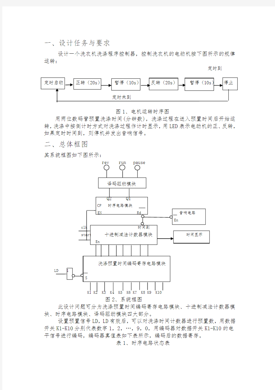
设计一个洗衣机洗涤程序控制器,控制洗衣机的电动机按下图所示的规律运转:
定时到
图1、电机运转时序图
用两位数码管预置洗涤时间(分钟数),洗涤过程在送入预置时间后开始运转,洗涤中按倒计时方式对洗涤过程作计时显示,用LED表示电动机的正、反转,如果定时时间到,则停机并发出音响信号。
二、总体框图
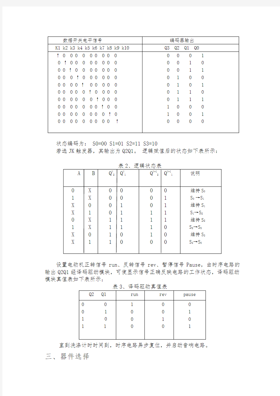
其系统框图如下图所示:
图2、系统框图
此设计问题可分为洗涤预置时间编码寄存电路模块、十进制减法计数器模块、时序电路模块、译码驱动模块四大部分。
设置预置信号LD,LD有效后,可以对洗涤时间计数器进行预置数,用数据开关K1-K10分别代表数字1,2,…,9,0,用编码器对数据开关K1-K10的电平信号进行编码,编码器真值表如下表所示,编码后的数据寄存。
表1、时序电路状态表
状态编码为: S0=00 S1=01 S2=11 S3=10
若选JK触发器,其输出为Q2Q1。逻辑赋值后的状态如下表所示:
设置电动机正转信号run、反转信号rev、暂停信号Pause,由时序电路的输出Q2Q1经译码驱动模块,可使显示信号正确反映电路的工作状态,译码驱动模块真值表如下表所示:
直到洗涤计时时间到,时序电路异步复位,并启动音响电路。
三、器件选择
用QUARTUSⅡ软件中Altera公司Cyclone系列的EP1C2Q240C8芯片实现仿真,EDA试验箱上的EP1C12核心板中的PB[0]、PB[1]、PB[2]、三个LED灯、数码管和开关SW13-SW16用于硬件调试,下载接口是数字芯片下载接口(DIGITAL JTAG)。
四、功能模块
1、预置时间和编码电路(settime):
library ieee;
use
entity settime is
port(load:in std_logic; --用来进行数据的读入
time_input:in std_logic_vector(3 downto 0); --通过开关进行输入
time_set:out std_logic_vector(7 downto 0) );
end settime;
set architecture time of settime is
signal p1:std_logic_vector(7 downto 0);
begin
process(load)
begin
if(load'event and load='1')
then
case time_input is
when "0000"=>p1<="00000001";
when "0001"=>p1<="00000010";
when "0010"=>p1<="00000011";
when "0011"=>p1<="00000100";
when "0100"=>p1<="00000101";
when "0101"=>p1<="00000110";
when "0110"=>p1<="00000111";
when "0111"=>p1<="00001000";
when "1000"=>p1<="00001001";
when "1001"=>p1<="00010000";
when others=>p1<="00000000";
end case;
end if;
end process;
time_set<=p1;
end settime;
图3、settime模块
图4、 settime仿真图
time_input为通过开发板上按钮输入的信号,load为输入确认信号。本模块将输入的四位时间信息编码输出到减法计数器电路。
2、减法计数器(counter):
library ieee;
use
use
entity counter is
port(clk,start:in std_logic;
time_set:in STD_LOGIC_VECTOR(7 downto 0); --接受上一个模块输入的时间信号 time_remain:BUFFER STD_LOGIC_VECTOR(7 DOWNTO 0); --剩余时间的输出
time_over:buffer std_logic ); --time_over就是gameover end counter;
architecture counter of counter is
begin
process(clk)
variable time_second:integer range 0 to 59:=59; ---用来进行内部信息的记录
begin
if(clk'event and clk='1')
then --判断是否开始
if(start='0')
then
if(time_remain(7 downto 0)=0)
then
time_remain<=time_set;
else
time_remain(7 downto 4)<=time_remain(3 downto 0);
time_remain(3 downto 0)<=time_set(3 downto 0);
end if;
time_second:=59;
time_over<='1';
else
if(time_over='1')
then --判断时间是否已经结束
if(time_second=0 and time_remain(7 downto 0)=0)
then
time_over<='0';
else
if(time_second=0) --判断每一分钟的结束
then
if(time_remain(3 downto 0)=0)
then
time_remain(7 downto 4)<=time_remain(7 downto 4)-1;
time_remain(3 downto 0)<="1001";
time_second:=59;
else
time_remain(7 downto 4)<=time_remain(7 downto 4)-1;
time_remain(3 downto 0)<="1001";
time_second:=59;
end if;
else
time_second:=time_second-1;
end if;
end if;
end if;
end if;
end if;
end process;
end counter;
图5、counter模块
图6、counter仿真图
本模块中clk为系统时序脉冲信号,start为系统开始运行的信号,time_set 为从预置时间模块接收到的时间编码信号,time_remain为输出到数码管显示电路的时间信号,time_is_up为系统运行结束信号,可以用来控制蜂鸣器的通断。
在系统运行的开始时期,用户第一次输入的预置时间会被赋给个位,第二次
输入的时间会被赋给十位,可以进行多次输入,以前的会被覆盖。
3、数码管显示电路(showtime):
library ieee;
use showtime is
port(remain_time:in std_logic_vector(7 downto 0); --剩余时间的输入 clk:in std_logic;
minute,second:out std_logic; --用来标记当前显示的是个位还是十位
a,b,c,d,e,f,g:out std_logic );
end showtime;
architecture showtime of showtime is
signal temp:std_logic_vector(6 downto 0);
signal bcd:std_logic_vector(3 downto 0);
signal choose:std_logic; --用来转换分位和秒位 begin
process(clk)
begin
if(clk'event and clk='1')
then
choose<=not choose;
if(choose='1')
then
minute<='0';second<='1';
bcd<=remain_time(7 downto 4);
else
minute<='1';second<='0';
bcd<=remain_time(3 downto 0);
end if;
end if;
end process;
process(bcd)
begin
case bcd is --数码管显示编码
when "0000"=> temp<= "1111110" ;
when "0001"=> temp<= "0110000" ;
when "0010"=> temp<= "1101101" ;
when "0011"=> temp<= "1111001" ;
when "0100"=> temp<= "0110011" ;
when "0101"=> temp<= "1011011" ;
when "0110"=> temp<= "1011111" ;
when "0111"=> temp<= "1110000" ;
when "1000"=> temp<= "1111111" ;
when "1001"=> temp<= "1111011" ;
when others=> temp<= "1111011";
end case;
a<=temp(6);b<=temp(5);c<=temp(4);d<=temp(3);e<=temp(2);f<=temp(1);g<=temp(0); end process;
end showtime;
图7、showtime 模块
图8、 showtime仿真图
接收减法计数器电路传来的时间信息,进行实时译码显示,由于我们的实际是可以进行两位的时间显示的,所以开始的时候是用的两个数码管,后来见到硬件芯片上是只有一个,又修改成了一个,但为了进行两位的显示,我们就设计了两个小灯,每个小灯分别代表十位和个位,当某个小灯被点亮时代表当前显示的是对应位的数值,每个一秒转换一次,这样就可以实现两位的显示了。
4、电机运转时序控制电路(analyse):
library ieee;
use
use
entity analyse is
port(clk,start,time_over:in std_logic;
out_1,out_2:out std_logic); --两路输出用来编辑电机的正反装和暂停end analyse;
architecture analyse of analyse is
begin
process(clk)
variable state:std_logic;
variable wash_time: integer := 0;
variable wait_time: integer := 0;
begin
if(clk'event and clk='1')
then
if(start='0') --系统还没有开始工作
then
wash_time := 0;
wait_time := 0;
state := '0';
out_1<='0';out_2<='0';
else
if(time_over='1') --时间没有结束
then
if(wash_time=20)
then
if(wait_time=9)
then
wash_time:=0;
state:=not state;
else
wait_time:=wait_time+1;
end if;
else
wash_time:=wash_time+1; --时间已经结束,系统结束工作
wait_time:=0;
end if;
end if;
if(wash_time=20)
then
out_1<='0';out_2<='0';
else
if(state='0')
then
out_1<='1';out_2<='0';
else
out_1<='0';out_2<='1';
end if;
end if;
end if;
end if;
end process;
end analyse;
图9、analyse模块
图10、analyse仿真图
通过时钟的输入进行计算当前系统应该处的状态,并进行编码输出电机的运转状态。由于在显示以及输入的时候只有分钟,故需要内设一个秒的计时变量。
5、译码器(move):
library ieee;
use move is
port(
out_1,out_2:in std_logic; --用来编码正反转的输入
REV,RUN,PAUSE:buffer std_logic); --电机的三个状态
end move;
architecture move of move is
begin
REV<=out_2;RUN<=out_1;PAUSE<=not(out_1 OR out_2);
end move;
图11、move模块
图12、move仿真图
分析输入的电机转动编码信号,即为思路中的Q1何Q2,安排电机运行状态并进行输出。此模块较为简单,设计基本没什么难度。
6、分频电路(主程序中未包含):
library ieee;
use mytime is
port(
clk_in:in std_logic;
clk:buffer std_logic
);
end mytime;
architecture mytime of mytime is
begin
process(clk_in)
variable i:integer:=0;
begin
if(clk_in'event and clk_in='1')
then
i:=i+1;
end if;
if(i=100) then
clk<=not clk;
end if;
end process;
end mytime;
图13、mytime模块
7、主程序(wash)
library ieee;
use ;
entity wash is --所有的输入 port(
load:in std_logic;
time_input:in std_logic_vector(3 downto 0);
clk:in std_logic;
start:in std_logic;
time_set:buffer std_logic_vector(7 downto 0);
time_over:buffer std_logic;
REV,RUN,PAUSE:buffer std_logic;
a,b,c,d,e,f,g:buffer std_logic;
minute,second:buffer std_logic
);
end wash;
architecture wash of wash is
component settime
port(
load:in std_logic;
time_input:in std_logic_vector(3 downto 0); time_set:buffer std_logic_vector(7 downto 0) );
end component;
component counter
port(
clk,start:in std_logic;
remain_ time:in std_logic_vector(7 downto 0); time_set:buffer std_logic_vector(7 downto 0); time_over:buffer std_logic
);
end component;
component analyse
port(
clk,start,time_over:in std_logic;
out_1,out_2:in std_logic
);
end component;
component move
port(
out_1,out_2:in std_logic;
REV,RUN,PAUSE:buffer std_logic
);
end component;
signal remain_time:std_logic_vector(7 downto 0);
signal out_1,out_2:std_logic;
begin
settime1:settime port map (load,time_input,time_set);
counter1:counte port map (clk,start,time_set,tremain_ime,time_over);
showtime1:showtime port map (tremain_ime,clk,minute,second,a,b,c,d,e,f,g);
analyse1:analyse port map (clk,start,time_over,out_1,out_2);
move1:move port map (out_1,out_2,REV,RUN,PAUSE);
end wash;
图14、wash模块
五、总体设计电路图
系统运行过程如下:在系统进行运行之前,使用time_input按钮预置洗衣机运转时间,此时用户设定的时间通过数码管时时显示出来,计时设备选取的精度是分钟级,也就是说用户可以设定洗衣时间是多少分钟,范围为00-99。然后用户可以给出开始信号,系统开始运转并开始从预设时间倒计时,重复“正传->暂停->反转->暂停”的循环过程直至剩余时间变为零。数码管在系统的整个运行过程中时时显示剩余运转时间,由于我们选用的数码管是一个,故设定的是每隔一秒分别显示十位和个位。
根据以上需求分析,按照系统模块化设计的要求可将洗衣机控制器的电路设计为主要由五部分组成,包括:预设时间和编码电路、减法计数器电路、数码管显示电路、电机运转时序控制电路、译码器。
1、系统总体电路图如下:
图15、系统总体电路图
2、管脚分配:
图16、管脚分配图
3、仿真图以及波形:
图17、系统仿真图
仿真图中clk给是个上升沿,其中第一段10个上升沿RUN给出高电平,代表正转;第二段5个上升PAUSE给出高电平,代表暂停;第三段10个上升沿REV 给不高电平,代表反转;第四段5个上升沿PAUSE给出高电平,代表暂停;最后当到规定时间暂停并发出警告信号。
4、硬件连接:
FPGA芯片
输入clk-->PIN28,start-->PIN126,load-->PIN127,time_over-->PIN125,
分别对应IO3,PB[1],PB[1],PB[2];a-->PIN105,b-->PIN104,c-->PIN101,d-->PIN100,e-->PIN85,f-->PIN84,g-->P IN83,time_input[0]-->PIN94,time_input[1]-->PIN95,time_input[2]-->PIN9 8,time_input[3]-->PIN99, 分别对应数码管和SW13-SW16;
输出PAUSE-->PIN133,REV-->PIN132,RUN-->PIN133,
分别接IO9,IO10,IO11;minute-->PIN82,second-->PIN86;分别对应SW8,SW9;功能选择位VGA[3..0]状态为0001,即16位拨码SW1-SW16被选中输出到总线
D[15..0];IO9,I019,IO11连接L1,L2,L3 5、硬件下载:
图18 正转
图19 暂停
图20 反转
六、实验问题分析和经验总结:
关于这个洗衣机控制器,就是用模块化层次化的设计方法进行系统层的设计,这样分解下来,设计会更容易点,思路也比较简单。洗衣机控制器主要就只有三个状态,要实现几种状态的多次循环的改变,其他的还有计时和数码显示的功能,所以电路可以设计为大致五大部分:settime,counter,analyse,move,和showtime。通过每个模块的设计最后组装即可完成系统级的设计。在设计的时候,如果特别要注意各个模块之间接口的设计,要是接口不对,模块之间就没法实现组装。
七、心得体会
通过两周的课程设计,对于VHDL的设计方法大致有了一些技巧性的了解,位以后的硬件设计打下了基础,对FPGA的编程、定时器和计数器的设计都熟悉起来,加深了对时序组合电路的印象。
通过在网上进行各种资料的查询,也发现了其实FPGA的设计具有较好的前景,其功能的强大和设计方法的简单可靠。具有较强的适应能力和可移植性。这次课程设计使我懂得了理论与实际相结合是很重要的,只有理论知识是远远不够的,只有把所学的理论知识与实践相结合起来,从理论中得出结论,才能真正为社会服务,从而提高自己的实际动手能力和独立思考的能力。
电子课程设计
——洗衣机定时器的设计
学院:华科学院
专业班级:电子102201H
姓名:刘丹
学号: 0123
指导教师:李东红
2012年12月
目录
一、设计任务与要求 ------------------------------ 1
二、总体框图 ------------------------------------ 1
三、器件选择 ------------------------------------ 3
四、功能模块 ------------------------------------ 3
1、settime模块------------------------------- 3
2、counter模块 ------------------------------- 3
3、showtime 模块------------------------------ 6
4、analyse模块------------------------------- 7
5、move模块 ---------------------------------- 9
6、mytime模块-------------------------------- 10
7、wash模块 ---------------------------------- 11
五、总体设计电路图 ------------------------------- 12
1、系统总体电路图 ----------------------------- 13
2、管脚分配--------------------------------- 15
3、仿真图以及波形----------------------------- 15
4、硬件连接 ---------------------------------- 15
5、硬件下载 ---------------------------------- 16
六、实验问题分析和经验总结 ---------------------- 17
七、心得体会 ------------------------------------ 17