PLC控制电梯外文翻译

Variable Frequency Speed-regulation System of Elevator
Using PLC Technology
Abstract-In this paper, the system of variable frequency speed-regulation based on PLC was proposed. Firstly, the overall structure of control system was determined. Inverter and programmable logic controller were chosen to complete variable frequency speed-regulation. Secondly, parameters of inverter were set by develop system hardware. PLC drive selection and 110 points distribution were completed; rotary encoder was connected with PLC interface. Finally, the software flow charts and ladder programs were designed by analysis of elevator system on the basis of software design methods.
Keywords-variable frequency speed-regulation; program; logic controller; elevator control system
I. INTRODUCTION
Human power was used as simple lifting equipment before Christ in china, until now hand-gin still was used as lifting device for extraction wells water in some rural of northern areas. So China is one of the earliest countries of the world in the aspect of elevator prototype [1]. In 1854, Elisa Graves Otis from Americans had shown his invention at the World Expo to the world in the Crystal Palace from New York, which was the first safety elevator in history [2]. Since then, elevator has been widely used in the world.
In modem life and economic activity, elevator has become a sign of the city. Elevator has been used as essential vertical transportation equipment, especially in high-rise building. The control systems of relays were used in the conventional elevator, whose control functions and signal processing were realized by hardware. Most of electrical components were common control electrical appliances [3]. Such elevator has been produced with mature technology in the past years, which has been formed series of products. With the rapid development of social economy and improvement of life quality, the shortcomings from traditional elevator controlled by original DC converter and relay had been more and more obvious and exposed many problems: (I) the traditional elevator control system have high failure rate that were mainly due to numerous contacts, complexity of wiring circuit. In addition, electrical contacts were easy to bum out, which could result in poor contact. (2) Electrical controller and hardware wiring based on common method were difficult to achieve a more complex control function, that is, why the functions of system control were difficult to increase. (3)Electromagnetic agencies and contact action were so slow, mechanical and electromagnetic have large inertia. Therefore, the control precision of system was difficult to rise. (4)The traditional elevator control systems have some shortcomings, such as large structure, high energy consumption, serious mechanical noise and so on. (5) Due to line complex and high failure rate of control system, large maintenance workload and high cost were required. It was shown that we should execute a comprehensive transformation to the traditional elevator control system.
II. INVERTER PARAMETERS DESIGN
Elevators were used as vertical transport tool, which belong to potential energy load and require frequent start and stop [4]. With the change of the passenger capacities, up or down transformation, the motor has minimum load. When elevator was run in no load up-going or heavy load down-going, motor was used in the state of power generation. Similarly, the motor has maximum load when elevator was run in heavy load up-going or no load down-going, motor was
used in the state of power. Therefore, the motor was required to run in the four quadrants of axis [5]. The change of motor work states were realized by contactors in the traction motor of traditional elevator. Speed control of motor was completed by series resistance or series reactance in the stator circuit of two-speed asynchronous motor, which can not satisfy the comfort of passengers. Traditional relay control modes were replaced by PLC control method, which could gradually transited from DC speed adjusting system to AC variable frequency speed adjusting system in the modes of motor drag [6].
A. Inverter Type Select
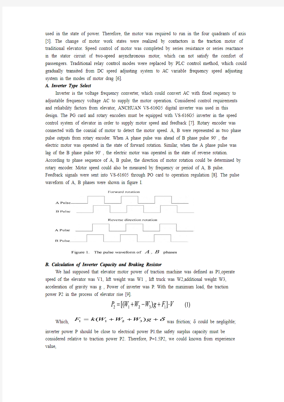
Inverter is the voltage frequency converter, which could convert AC with fixed requency to adjustable frequency voltage AC to supply the motor operation. Considered control requirements and reliability factors from elevator, ANCHUAN VS-616G5 digital inverter was used in this design. The PG card and rotary encoders must be equipped with VS-616G5 inverter in the speed control system of elevator in order to supply motor speed and feedback [7]. Rotary encoder was connected with the coaxial of motor to detect the motor speed. A, B were represented as two phase pulse outputs from rotary encoder. When A phase pulse was ahead of B phase pulse 90' , the electric motor was operated in the state of forward rotation. Similar, when the A phase pulse was lag of the B phase pulse 90' , the electric motor was operated in the state of reverse rotation. According to phase sequence of A, B pulse, the direction of motor rotation could be determined by rotary encoder. Motor speed could also be measured by frequency or period of A, B pulse. Feedback signals were sent into VS-61605 through PO card to operation regulation [8]. The pulse waveform of A, B phases were shown in figure I.
B. Calculation of Inverter Capacity and Braking Resistor
We had supposed that elevator motor power of traction machine was defined as P1,operate speed of the elevator was V1, lift weight was W1 , lift truck was W2,additional weight W3, acceleration of gravity was g , Power of inverter was P. With the maximum load, the traction power P2 in the process of elevator rise [9].
Which, was friction; δ could be negligible;
inverter power P should be close to electrical power P1.the safety surplus capacity must be considered relative to traction power P2. Therefore, P=1.5P2, we could known from experience value,
Therefore, the inverter capacity was selected about 15KW.
As elevator was potential energy load, variable frequency speed regulation system should have a brake function since elevator could generate renewable energy during the process of operation. When VS-61605 was used in the system of speed control, the braking resistors must also be configured. When the elevator was worked in the deceleration, the electric motor was run in the power generation state and feedback power to the inverter. DC part voltage from AC-
DC-AC inverter could increase when sync speed dropped [10].The role of braking resistor was feedback power and suppresses DC voltage. Renewable energy were consumed in the braking resistor through the brake unit by use of the energy consumption braking mode, which has lower cost and good results.
The value of energy consumption braking resistor R2 should be made the value of the braking current I z does not exceed the half of the inverter current.
Which, U0 was defined as DC bus voltage of inverter in the rated state, R2>30Ω.Because the work of braking resistor was not continuous long-term work, the power could be significantly less than the power consumed.
III. HARDWARE DESIGN
The hardware of elevator control system was composed by Car Lateral Control Panel, Elevator Landing Door Signal, Inverter, and Adjustable Speed Drives. The structure chart of control system was shown in figure 2.
The function of adjustable speed was completed by inverter and logic control section was
completed by the PLC controller. The logic relatives of various signals were responsible for PLC to send on/off control signals to inverter. At the same time, the working status from inverter was transported to PLC .the bilateral contact relationships were established. The speed loop and position loop were established by established to complete speed test and feedback by equip with PO card and Rotary Encoder, which could be connected with Motor coaxial connector. In addition, the system also must be configured with the brake resistor [11]. When the elevator deceleration, DC voltage hypertension must be suppressed due to motor working in the state of renewable generation power, which will back power to inverter.
A. Motor Drive Control System
Similar as other elevator control systems, control system based on PLC was also mainly composed of two parts, that is, signal control system and motor drive control system. The basic structure of PLC elevator control system was shown in figure 3. The main hardware had been included by PLC controller, CPU memory, machinery, car lateral control panel, call elevator plate outside of hall, layer device, gate machine, adjustable speed drives, main motor drive system and so on.
According to the position detection method of Car Lateral from rotary encoder, a high-speed counter was required in the programmable logic controller. FX2N PLC from Mitsubishi Company made in Japan was chosen. The control instructions from elevator were realized by PLC software. The management and control functions of command signals were completed by PLC controller, such as start, acceleration/deceleration and stop of elevator traction motor and open/close door motor, operate direction, floor display, landing call, car lateral internal operation command, security and so on.
B. Signal Control System
Input control signal to the PLC have included that run mode selection, operation control signal, Car Lateral internal instructions, elevator plate calls, signal security information, rotary encoders, optical pulse, on/off door controller and limit level signals, door area and flat layer signals. The control system of six level elevators was used as an example in this paper. According to the need of control switch, about 48 input points and 30 output points need to be control. FX2N a 128MR model of PLC was chosen when we have considered about 10% to 15% surplus capacity of control points [12]. The signal control system of elevator was shown in figure 4.
IV. SOFTW ARE PROCESS
A. Main Program
Control system proposed from this paper was a system of collective selective control. The modular programming methods were used to classify various properties of output signal, medium registers were used to connect different modules to transmit information. System software could be divided into some follow modules, that is, floor detection circuit module, seven segment LED display floor circuit module, elevator direction selection circuit module, deceleration point signal generator circuit modules, on/off door of elevator car lateral circuit module, button memory lights display circuit module and the other modules. In the floor detection circuit module, floor encoding were read into and memory signals were saved in the corresponding registers until the floor changes. LED display was controlled in the seven segment display circuit module. Elevator up or down judgments in response to call the elevator were completed in the elevator direction selection circuit module. Main program flow chart of system software was shown in figure 5.
B. Floor Display Program
Elevator will running in the deceleration state when current floor consistent with target detection floor. During the process of operation, elevator will go through many floor detection points. Deceleration notification will be emitted only when elevator reach the detect point of goal floor. After receive deceleration notification signal, elevator had started slow down. The flow chart of floor display program was shown in figure 6.
PLC output ports were directly connected with seven- segment LED, which need not external hardware decoder. Seven-segment LED was compiled by PLC software to directly display floor number. The seven-segment LED digital tube was commonly used, which is a digital distribution in a plane by a number of light-emitting diodes or liquid crystal segments to form a variety of digital code. Seven-segment LED digital tube was distributed in a plane. Digital codes of floor were composed by some light-emitting diodes or liquid crystal segments. Seven segment LED
display circuit was shown as figure 7.
In the display circuit of seven-segment code, input pin a, b, c, d, e, f, g of LED were
connected with 24V power supply, then the corresponding section will be lighted, the control terminals Y10 -Y16 of programmable logic controller will be closed or open, which could control on or off state to appear the corresponding value in the appropriate section of LED. Digital display of values and correspond pins were shown in table I. Among them, output state I was defined as bright field of the seven segments LED; output state 0 was defined as dark field of the seven segments LED.
V . CONCLUDES
Variable frequency speed-regulation and programmable logic controller technology were used to transform old elevator. The reliability of the elevator was improved through reasonable equipment selection, parameter setting and software design. The elevators after transformation have obvious advantages such as structure compact, low noise, high efficiency, simply
maintenance and low failure rate. The elevator based on variable frequency speed- regulation and programmable logic controller technology have improve passenger comfort and reliable.
Maintenance costs and power consumption of motor were reduced significantly. But there are still many areas for improvement: (I) Changed with fluctuate in traffic; the functions of select direction of elevator were optimized to achieve the purpose of efficient transport of passengers. (2)
Emergency approaches will be increased in the fault conditions. These problems will to be perfect in the future.
ACKNOWLEDGMENT
First and foremost, I would like to show my deepest gratitude to my supervisor, Dr. Zhang. a respectable, responsible and resourceful scholar, who has provided me with valuable guidance in every stage of the writing of this thesis. I shall extend my thanks to Mr. Wang for all his kindness and help. I would also like to thank all my teachers who have helped me to develop the
fundamental and essential academic competence. My sincere appreciation also goes to all my friends for their encouragement and support.
采用PLC 技术的电梯变频调速系统
摘要:本文提出了基于PLC 测定的变频调速调节系统。首先,对控制系统的整体结构
进行了测定。选择变频器和可编程逻辑控制器,来完成变频调速调节。其次,设定变
频器的系统硬件参数。选择PLC 的驱动点和I/O 端子的分配,旋转编码器与PLC 的接口连接。最后,在软件设计的基础上,完成软件流程图和梯形图程序,分析出电梯设
计系统的方法。
关键词:变频调速;可编程逻辑控制器;电梯控制系统。
一、引言
在早期的中国,人的力量被用来作为简单的起重设备,直到现在,北方地区的一些农村手动提取井水的升降装置仍在使用。因此,中国是世界上最早的在电梯的原型[1]方面有建树的国家之一。1854 年,来自美国的格雷夫斯在纽约水晶宫世博会上向世界展示了他的发明,这是史上第一部安全电梯[2]。此后,电梯在世界上得到了广泛的应用。
在现代生活和经济活动中,电梯已经成为了城市的标志。电梯作为重要的垂直运输工具,尤其是在高层建筑中。继电器控制系统曾被用于常规的电梯中,其控制功能和信号处理由硬件来实现。许多的电气元件来共同控制电器[3]。在过去的几年,电梯的生产技术愈发成熟,已形成系列产品。随着经济社会的快速发展和生活质量的提高,由传统的DC 转换器和继电器控制的电梯,缺点越来越明显,暴露出诸多问题:(1)传统的电梯控制系统故障率较高,主要是由于多次接触,复杂的布线电路。此外,电接点易燃,这可能会导致接触不良。(2)电机控制器与硬件接线根据常用的方式,难以实现更复杂的控制功能,也就是难以提高系统控制的性能。(3)电磁机构和接触点动作慢,机械和电磁惯性大。因此,系统的控制精度难以提高。(4)传统的电梯控制系统也存在一些缺点,如结构庞大,能耗高,机械噪声大等。(5)由于线路复杂、故障率高,必然导致控制系统维护量大、成本高。结果表明,我们应该来完成传统的电梯控制系统的完全改造。
二、变频器参数设定
电梯作为垂直运输的工具,属于位能负载设备,并需要频繁启动和停止[4]。电梯随着载客量,向上、向下变化,电机的最小负荷而变化。当电梯在无负载或重负载下,电机在发电状态。同样地,电机具有最大负载时,在重负载上行或无负载下行状态时,电机处于用电状态。因此,电动机的运行轴[5]的四个象限中。传统的电梯由牵引电动机驱动,电机的工作状态的变化,由接触器实现。在定子电路的串联电阻或串联电抗,且电动机的速度控制由双速异步电动机来完成,不能满足乘客的舒适性。用PLC 来取代传统继电器控制模式,它可以在电机拖动过程中,从直流调速的模式逐步过渡到交流变频调速。
A.变频器的选择
变频器可以实现电压频率的转换,它可以转换交流与固定频率,交流电压频率调节后供给电机使用。考虑从电梯的控制要求和可靠性,本次设计使用安川VS-616G5数字变频器。在速度控制系统的电梯中PG 卡和旋转编码器必须配备于VS-616G5 变频器,以供给电动机速度控制和反馈动作[7]。通过电机同轴连接的旋转编码器来检测电机的转速。A,B 分别表示为两相旋转编码器的脉冲输出。当 A 相脉冲超前 B 相脉冲90 度时,电动机正向旋转的状态。类似的,当A 相脉冲滞后B 相脉冲90 度时,电动机操作的反向旋转状态。根据A,B 脉冲的相序,确定电机的旋转方向。测量电机转速的同时也可以测量出A,B 脉冲频率或周期。反馈信号发送到VS-61605 通过PG卡到变频器[8]。图一所示的脉冲波形A,B。
B.变频器容量的计算和制动电阻
我们定义电梯曳引机的电机功率为P1,运行的电梯速度为V1,起重量为W1,W2,额外的重量W3,重力加速度为G,电源逆变器是P.随着的最大负载在电梯上升[9]的过程中,牵引功率为P2。
其中,F1 为摩擦力,δ可忽略不计。变频器的功率P 接近电梯电源P1,安全性能,必须考虑牵引功率P2。P=1.5P2,因此,我们可以得知经验值,
此时,变频器的容量约为15KW。
随着电梯潜在的能量的加载,可变的频率速度调控系统应该有一个制动函数,因为电梯可能在操作过程中产生可再生的能量。当系统速度控制中使用了VS-616G5,必须配置制动电阻器。当电梯被用在减速过程时,所述电动从发电状态,反馈到变频器的发电状态。DC 从AC-DC-AC 逆变器可以增加,当同步速度下降时。制动电阻器的作用是反馈信号抑制直流电压。可再生能源的被消耗了在制动电阻上,通过所述制动单元的制动模式,该模式具有较低的成本和良好的结果。
能源消耗制动电阻器R2,制动的电流I z 的值不超过该的变频器电流的二分之一。其中,U0 被定义为变频器额定电压,R2 大于30 欧姆。因为制动电阻不是长期工作的,电源可能小于所消耗的功率。
三、硬件设计
电梯控制系统的硬件组成,由汽车横向控制面板,电梯厅门信号,变频器,调速传动。图2 中所示的控制系统的结构图。
速度可调的功能,由变频器和PLC 控制器的逻辑控制部分完成。负责PLC 发送开/关控制信号,逆变器的各种信号的逻辑亲属。在同一时间,变频器的工作信号被输送到PLC,双边接触关系成立。由PG 卡和旋转编码器与电机同轴连接,可连接建立完成速度测试和反馈设备的速度环和位置环。此外,该系统还必须配置制动电阻器[11]。当电梯减速时,必须抑制由电机工作的可再生能源发电功率,这将反馈电信号到变频器。
A.电机驱动控制系统
类似其他的电梯控制系统,基于PLC 的控制系统主要由两部分组成,即信号控制系统和电动机驱动控制系统。PLC 的电梯控制系统的基本结构如图3 所示。主要硬件包括PLC 控制器,CPU 内存,机械,汽车侧控制面板,呼叫电梯外盘层设备,大厅,门机,调速驱动器,主电机驱动系统等。
根据旋转编码器位置检测方法,需要一个高速计数器在可编程逻辑控制器中。在日本三菱公司的FX2N PLC 中,从电梯控制指令由PLC 软件实现。完成管理和控制功能的指令信号由PLC 控制器,如启动,加速/减速和停止电梯牵引电机和电机开/关门,方向确定,楼层显示,层站呼梯操作命令,安全指令等。
B.信号控制系统
输入控制信号给PLC 运行模式选择,操作控制信号,内部指令,升降呼叫信号,安全性信息,旋转编码器,光脉冲,打开/关闭门控制器和限制电平信号,轿厢门和平面层信号。在六级电梯的控制系统中,使用约48 个输入点和30 个输出点。选择FX2N 128MR 的PLC 型号。图4 中所示的信号控制系统的电梯。
四、软件过程
A.主程序
本文提出的控制系统是一个系统的集城选择控制装置。采用模块化编程方法,将输出信号的各种属性进行分类,其中寄存器用来连接不同的模块并传输信息。系统软件可分为一些后续的模块,也就是层检测电路模块,七段数码管显示楼层电路模块,电梯方向选择电路模块,减速点信号发生器电路模块,开/关电梯轿厢门模块,按钮记忆灯显示电路模块和其他模块。在其它检测电路模块中,读入内存信号并保存在相应的寄存器中,直到轿厢地板的变化。LED 显示屏控制七段显示器电路模块。电梯向上或向下的判断响应呼叫电梯,在电梯方向选择电路模块。系统软件的主程序流程图如图5 所示。
B.楼层显示程序
电梯在减速运行时,检测楼层信号位置。在操作的过程中,电梯会经过许多楼层检测点。减速将发出通知,只有当电梯到达目标楼层的检测点。收到减速通知信号后,电梯已开始放缓。如图6 中所示地显示程序的流程图中。七段LED,不需要外部硬件解码器,直接连接PLC 的输出端口。七段LED 编译PLC 软件直接显示楼层号。七段LED 数码管常用的,这是一个数字由多个发光二极管或液晶段,分布在一个平面上形成各种不同的数字码。七段LED 数码管分布在一个平面上。
五、总结
变频调速调节和可编程逻辑控制器技术被用来改造电梯。电梯的可靠性进行了改进,通过合理的设备选型,参数设置和软件设计。改造后的电梯有明显的优点,如结构紧凑,噪音低,效率高,维护简单,故障率低。电梯的基础上变频调速,可编程逻辑控制器技术已提高乘客的舒适性和可靠性。显着降低电机的维护成本和功耗。但也有仍然有很多需要改进的地
方:(一)改变流量波动;电梯选择方向的功能进行了优化,实现高效运送乘客的目的。(2)紧急方法将增加在故障条件。这些问题将在未来来完善。
基于plc的三层电梯控制系统设计
摘要 电梯是高层建筑不可缺少的运输工具,用于垂直运送乘客和货物,传统的电梯控制系统主要采用继电器--接触器进行控制,其缺点是触点多,故障率高、可靠性差、维修工作量大等,而采用PLC组成的控制系统可以很好地解决上述问题。本论文通过讨论电梯控制系统的组成,阐述可编程控制器(用三菱PLC编程的程序控制方式,提出了三层电梯的程、组成,列出了具体的主要硬件电路、电梯的控制梯形图及指令表。并给出了系统组成框图和程序流程图,在分析、处理随机信号逻辑关系的基础上,提出了计了一套完整的电梯控制系统方案。触点多,故障率高、可靠性差、安装调试周期长、维修工作量大、接线复杂等缺点。使电梯运行更加安全、方便、舒适。在PLC课程设计中,我组设计了一个三层电梯控制系统,并且将西门子公司S7-200系列可编程控制器与其结合并应用起来,在学完《电气控制与PLC应用》课程后,我们在设计过程中较为得心应手,不至于从头开始。整个过程包括了方案讨论,程序设计,程序修改,上机调试等,在程序设计方面花了比较多的时间,主要考虑到电梯分别停在一层、二层和三层时在其他楼层呼叫等各种情况。每当遇到困难时,我组都积极与老师联系讨论,深入分析研究问题,在整个过程中,我与我的组员都相互配合,相互学习。 关键字:PLC;电梯;升降;梯形图;系统组成框图
In this paper The elevator is an indispensable means of transport for the high-rise building, used for vertical transporting passengers and cargo, the traditional elevator control system mainly adopts relay - contactor to control, its shortcomings is the number of contact, such as high failure rate and poor reliability, maintenance workload is big, and composed of PLC control system is a good way to solve the above problems. Through discussing the composition of the elevator control system, this paper expounds the programmable controller (with mitsubishi PLC programming way of process control, puts forward the three layers of elevator ride, and lists the specific of the main hardware circuit, elevator control ladder diagram and instruction list. And the system composition block diagram and program flow chart is given, based on the analysis, processing, on the basis of random signal logic relation, put forward the plan for a complete set of the elevator control system scheme. Contact, high failure rate, poor reliability, installation and debugging cycle is long, maintenance workload, such as complex wiring faults. Make the elevator running more safe, convenient and comfortable. In the PLC course design, I have come up with a three layers of elevator group control system, and the Siemens S7-200 series programmable controller and its application and combining, after completing the curriculum, electrical control and PLC application we in the design process is relatively with ease, not from the beginning. The whole process including the solution discussion, program design, program changes, computer debugging, etc., spent more time on program design, main consideration to the elevator stop on the first floor, respectively the second and third floors in other situations such as floor call. Whenever encounter difficulties, I actively
毕业设计外文翻译附原文
外文翻译 专业机械设计制造及其自动化学生姓名刘链柱 班级机制111 学号1110101102 指导教师葛友华
外文资料名称: Design and performance evaluation of vacuum cleaners using cyclone technology 外文资料出处:Korean J. Chem. Eng., 23(6), (用外文写) 925-930 (2006) 附件: 1.外文资料翻译译文 2.外文原文
应用旋风技术真空吸尘器的设计和性能介绍 吉尔泰金,洪城铱昌,宰瑾李, 刘链柱译 摘要:旋风型分离器技术用于真空吸尘器 - 轴向进流旋风和切向进气道流旋风有效地收集粉尘和降低压力降已被实验研究。优化设计等因素作为集尘效率,压降,并切成尺寸被粒度对应于分级收集的50%的效率进行了研究。颗粒切成大小降低入口面积,体直径,减小涡取景器直径的旋风。切向入口的双流量气旋具有良好的性能考虑的350毫米汞柱的低压降和为1.5μm的质量中位直径在1米3的流量的截止尺寸。一使用切向入口的双流量旋风吸尘器示出了势是一种有效的方法,用于收集在家庭中产生的粉尘。 摘要及关键词:吸尘器; 粉尘; 旋风分离器 引言 我们这个时代的很大一部分都花在了房子,工作场所,或其他建筑,因此,室内空间应该是既舒适情绪和卫生。但室内空气中含有超过室外空气因气密性的二次污染物,毒物,食品气味。这是通过使用产生在建筑中的新材料和设备。真空吸尘器为代表的家电去除有害物质从地板到地毯所用的商用真空吸尘器房子由纸过滤,预过滤器和排气过滤器通过洁净的空气排放到大气中。虽然真空吸尘器是方便在使用中,吸入压力下降说唱空转成比例地清洗的时间,以及纸过滤器也应定期更换,由于压力下降,气味和细菌通过纸过滤器内的残留粉尘。 图1示出了大气气溶胶的粒度分布通常是双峰形,在粗颗粒(>2.0微米)模式为主要的外部来源,如风吹尘,海盐喷雾,火山,从工厂直接排放和车辆废气排放,以及那些在细颗粒模式包括燃烧或光化学反应。表1显示模式,典型的大气航空的直径和质量浓度溶胶被许多研究者测量。精细模式在0.18?0.36 在5.7到25微米尺寸范围微米尺寸范围。质量浓度为2?205微克,可直接在大气气溶胶和 3.85至36.3μg/m3柴油气溶胶。
控制系统基础论文中英文资料外文翻译文献
控制系统基础论文中英文资料外文翻译文献 文献翻译 原文: Numerical Control One of the most fundamental concepts in the area of advanced manufacturing technologies is numerical control (NC).Prior to the advent of NC, all machine tools were manual operated and controlled. Among the many limitations associated with manual control machine tools, perhaps none is more prominent than the limitation of operator skills. With manual control, the quality of the product is directly related to and limited to the skills of the operator . Numerical control represents the first major step away from human control of machine tools. Numerical control means the control of machine tools and other manufacturing systems though the use of prerecorded, written symbolic instructions. Rather than operating a machine tool, an NC technician writes a program that issues operational instructions to the machine tool, For a machine tool to be numerically controlled , it must be interfaced with a device for accepting and decoding the p2ogrammed instructions, known as a reader. Numerical control was developed to overcome the limitation of human operator , and it has done so . Numerical control machines are more accurate than manually operated machines , they can produce parts more uniformly , they are faster, and the long-run tooling costs are lower . The development of NC led to the development of several other innovations in manufacturing technology: 1.Electrical discharge machining. https://www.360docs.net/doc/c214029460.html,ser cutting. 3.Electron beam welding.
PLC外文翻译
外文翻译 原文:The open system merit of Computer Numerical Control The open system merit is the system simple, the cost low, but the shortcoming is the precision is low. The reverse gap, the guide screw pitch error, stop inferiorly can affect the pointing accuracy by mistake. Following several kind of improvements measure may cause the pointing accuracy distinct improvement. 1. reverse gap error compensates The numerical control engine bed processing cutting tool and the work piece relative motion is depends upon the drive impetus gear,the guide screw rotation, thus the impetus work floor and so on moves the part to produce moves realizes. As traditional part gear, guide screw although the manufacture precision is very high, but always unavoidably has the gap. As a result of this kind of gap existence, when movement direction change, starts the section time to be able to cause inevitably actuates the part wasting time, appears the instruction pulse to push the motionless functional element the aspect. This has affected the engine bed processing precision, namely the instruction pulse and actual enters for the step does not tally,has the processing error therefore, the split-ring numerical control system all establishes generally has the reverse gap error compensatory function, with by makes up which wastes time the step reverse gap difference compensates is first actual reverse enters for the error, converts the pulse equivalent number it, compensates the subroutine as the gap the output, when the computer judgment appears when instruction for counter motion, transfers the gap to compensate the subroutine immediately, compensates the pulse after the output to eliminate the reverse gap to carry on again normally inserts makes up the movement. 2. often the value systematic characteristic position error compensates A kind of storehouse by transfers for the designer. Like this in the components design stage, the designer only must input the characteristic the parameter, the system direct production characteristic example model: We must save the related characteristic class in the database the structure information, the database table collection are use in saving this part of related information. According to the characteristic type definition need, we defined the characteristic class code table, the
关于电梯的外文翻译
双控电梯 PLC控制外文翻译 Abstract Microelectronic technology's development, elevator's dragging way and the control method has had the very big change, the exchange velocity modulation is the current elevator dragging main development direction. At present the lift control system mainly has three control modes: Following electric circuit control system (“early installment elevator many black-white control system), PLC control system, microcomputer control system. Because the black-white control system the failure rate is high, the reliability is bad, control mode not nimble as well as consumed power big and so on shortcomings, at present has been eliminated gradually. Although the microcomputer control system has the strong function in the intelligent control aspect, but also has the interference rejection to be bad, the system design is complex, generally the servicemen master flaws with difficulty and so on its service technology. But PLC control system, because moves the reliability to be high, the use service is convenient, anti-jamming, the design and the debugging cycle is short and so on merits, time is taken seriously the people and so on merits, have become present use most control modes in the lift control system, at present also widely use in the tradition black-white control system's technological transformations. The origin and development of the elevator Elevator in the Chinese dictionary explanation: building electricity powered lift, instead of walking up and down the stairs. When it comes to lift from the origin of the 2600 BC Egyptians built in Pyramid using the original lifting system to start, but this kind of crane energy are human. By 1203, two French monastery installed a crane, the difference is just the machine is the use of donkey as power, load by around a large drum rope for hoisting. This method has been used to modern until Watt invented the steam engine, in about1800, mine owners can use the crane to mine in coal transportation. For hundreds of years, people made various types of elevators, they all have a common defect: as long as the lifting rope snaps, lifting ladder he rapidly hit bottom layer. 1854 Otis design a brake: in the lift platform mounted on top of a truck with a spring and a brake lever and Lift Wells Road on both
基于单片机的步进电机控制系统设计外文翻译
毕业设计(论文)外文资料翻译 学院:机械工程学院 专业:机械设计制造及其自动化 姓名: 学号:XXXXXXXXXX 外文出处:《Computational Intelligence and (用外文写)Design》 附件: 1.外文资料翻译译文;2.外文原文。 注:请将该封面与附件装订成册。
附件1:外文资料翻译译文 基于微型计算机的步进电机控制系统设计 孟天星余兰兰 山东理工大学电子与电气工程学院 山东省淄博市 摘要 本文详细地介绍了一种以AT89C51为核心的步进电机控制系统。该系统设计包括硬件设计、软件设计和电路设计。电路设计模块包括键盘输入模块、LED显示模块、发光二极管状态显示和报警模块。按键可以输入设定步进电机的启停、转速、转向,改变转速、转向等的状态参数。通过键盘输入的状态参数来控制步进电机的步进位置和步进速度进而驱动负载执行预订的工作。运用显示电路来显示步进电机的输入数据和运行状态。AT89C51单片机通过指令系统和编译程序来执行软件部分。通过反馈检测模块,该系统可以很好地完成上述功能。 关键词:步进电机,AT89C51单片机,驱动器,速度控制 1概述 步进电机因为具有较高的精度而被广泛地应用于运动控制系统,例如机器人、打印机、软盘驱动机、绘图仪、机械式阀体等等。过去传统的步进电机控制电路和驱动电路设计方法通常都极为复杂,由成本很高而且实用性很差的电器元件组成。结合微型计算机技术和软件编程技术的设计方法成功地避免了设计大量复杂的电路,降低了使用元件的成本,使步进电机的应用更广泛更灵活。本文步进电机控制系统是基于AT89C51单片机进行设计的,它具有电路简单、结构紧凑的特点,能进行加减速,转向和角度控制。它仅仅需要修改控制程序就可以对各种不同型号的步进电机进行控制而不需要改变硬件电路,所以它具有很广泛的应用领域。 2设计方案 该系统以AT89C51单片机为核心来控制步进电机。电路设计包括键盘输入电路、LED显示电路、发光二极管显示电路和报警电路,系统原理框图如图1所示。 At89c51单片机的P2口输出控制步进电机速度的时钟脉冲信号和控制步进电机运转方向的高低电平。通过定时程序和延时程序可以控制步进电机的速度和在某一
基于PLC的电梯控制系统设计报告
《基于PLC的电梯电梯控制》 课程设计 学生姓名:李锦文 学号: 6100310066 专业班级:自动化101班 指导老师:曾芸 2014年 01 月 14日
目录 一、概述 1、PLC控制技术简介 (2) 2、PLC的分类和特点 (2) 3、PLC的结构和工作原理 (3) 4、PLC程序的表达方式 (3) 5、PLC的工作方式 (5) 二、PLC的系统硬件设计 1、可编程控制器机型的选择 (5) 2、输入/输出模块的选择 (6) 3、输入/输出端地址分配 (6) 4、输入/输出端接线图 (8) 三、PLC的系统软件设计 1、PLC控制功能流程图 (9) 2、PLC梯形图程序设计 (10) 四、总结 (12) 五、心得体会 (13) 六、参考文献 (13)
一、概述 (一)PLC控制技术简介 可编程逻辑控制器(Programmable Logic Controller,PLC),它采用一类可编程的存储器,用于其内部存储程序,执行逻辑运算、顺序控制、定时、计数与算术操作等面向用户的指令,并通过数字或模拟式输入/输出控制各种类型的机械或生产过程。 可编程序控制器,是微机技术与继电器常规控制技术相结合的产物,是在顺序控制器和微机控制器的基础上发展起来的新型控制器,是一种以微处理器为核心用作数字控制的专用计算机。它不仅充分利用微处理器的优点来满足各种工业领域的实时控制要求,同时也照顾到现场电气操作维护人员的技能和习惯,摒弃了微机常用的计算机编程语言的表达方式,独具风格地形成一套以继电器梯形图为基础的形象编程语言和模块化的软件结构,使用户程序的编制清晰直观、方便易学,调试和查错都很容易。用户买到所需的PLC后,只需按说明书或提示,做少量的安装接线和用户程序的编制工作,就可灵活而方便地将PLC应用于生产实践。 (二)PLC的分类与特点 PLC一般可按I/O点数和结构形式分类。按I/O点数可分为小型、
毕业设计(论文)外文资料翻译〔含原文〕
南京理工大学 毕业设计(论文)外文资料翻译 教学点:南京信息职业技术学院 专业:电子信息工程 姓名:陈洁 学号: 014910253034 外文出处:《 Pci System Architecture 》 (用外文写) 附件: 1.外文资料翻译译文;2.外文原文。 指导教师评语: 该生外文翻译没有基本的语法错误,用词准确,没 有重要误译,忠实原文;译文通顺,条理清楚,数量与 质量上达到了本科水平。 签名: 年月日 注:请将该封面与附件装订成册。
附件1:外文资料翻译译文 64位PCI扩展 1.64位数据传送和64位寻址:独立的能力 PCI规范给出了允许64位总线主设备与64位目标实现64位数据传送的机理。在传送的开始,如果回应目标是一个64位或32位设备,64位总线设备会自动识别。如果它是64位设备,达到8个字节(一个4字)可以在每个数据段中传送。假定是一串0等待状态数据段。在33MHz总线速率上可以每秒264兆字节获取(8字节/传送*33百万传送字/秒),在66MHz总线上可以528M字节/秒获取。如果回应目标是32位设备,总线主设备会自动识别并且在下部4位数据通道上(AD[31::00])引导,所以数据指向或来自目标。 规范也定义了64位存储器寻址功能。此功能只用于寻址驻留在4GB地址边界以上的存储器目标。32位和64位总线主设备都可以实现64位寻址。此外,对64位寻址反映的存储器目标(驻留在4GB地址边界上)可以看作32位或64位目标来实现。 注意64位寻址和64位数据传送功能是两种特性,各自独立并且严格区分开来是非常重要的。一个设备可以支持一种、另一种、都支持或都不支持。 2.64位扩展信号 为了支持64位数据传送功能,PCI总线另有39个引脚。 ●REQ64#被64位总线主设备有效表明它想执行64位数据传送操作。REQ64#与FRAME#信号具有相同的时序和间隔。REQ64#信号必须由系统主板上的上拉电阻来支持。当32位总线主设备进行传送时,REQ64#不能又漂移。 ●ACK64#被目标有效以回应被主设备有效的REQ64#(如果目标支持64位数据传送),ACK64#与DEVSEL#具有相同的时序和间隔(但是直到REQ64#被主设备有效,ACK64#才可被有效)。像REQ64#一样,ACK64#信号线也必须由系统主板上的上拉电阻来支持。当32位设备是传送目标时,ACK64#不能漂移。 ●AD[64::32]包含上部4位地址/数据通道。 ●C/BE#[7::4]包含高4位命令/字节使能信号。 ●PAR64是为上部4个AD通道和上部4位C/BE信号线提供偶校验的奇偶校验位。 以下是几小结详细讨论64位数据传送和寻址功能。 3.在32位插入式连接器上的64位卡
速度控制系统设计外文翻译
译文 流体传动及控制技术已经成为工业自动化的重要技术,是机电一体化技术的核心组成之一。而电液比例控制是该门技术中最具生命力的一个分支。比例元件对介质清洁度要求不高,价廉,所提供的静、动态响应能够满足大部分工业领域的使用要求,在某些方面已经毫不逊色于伺服阀。比例控制技术具有广阔的工业应用前景。但目前在实际工程应用中使用电液比例阀构建闭环控制系统的还不多,其设计理论不够完善,有待进一步的探索,因此,对这种比例闭环控制系统的研究有重要的理论价值和实践意义。本论文以铜电解自动生产线中的主要设备——铣耳机作为研究对象,在分析铣耳机组各构成部件的基础上,首先重点分析了铣耳机的关键零件——铣刀的几何参数、结构及切削性能,并进行了实验。用电液比例方向节流阀、减压阀、直流直线测速传感器等元件设计了电液比例闭环速度控制系统,对铣耳机纵向进给装置的速度进行控制。论文对多个液压阀的复合作用作了理论上的深入分析,着重建立了带压差补偿型的电液比例闭环速度控制系统的数学模型,利用计算机工程软件,研究分析了系统及各个组成环节的静、动态性能,设计了合理的校正器,使设计系统性能更好地满足实际生产需要 水池拖车是做船舶性能试验的基本设备,其作用是拖曳船模或其他模型在试验水池中作匀速运动,以测量速度稳定后的船舶性能相关参数,达到预报和验证船型设计优劣的目的。由于拖车稳速精度直接影响到模型运动速度和试验结果的精度,因而必须配有高精度和抗扰性能良好的车速控制系统,以保证拖车运动的稳速精度。本文完成了对试验水池拖车全数字直流调速控制系统的设计和实现。本文对试验水池拖车工作原理进行了详细的介绍和分析,结合该控制系统性能指标要求,确定采用四台直流电机作为四台车轮的驱动电机。设计了电流环、转速环双闭环的直流调速控制方案,并且采用转矩主从控制模式有效的解决了拖车上四台直流驱动电机理论上的速度同步和负载平衡等问题。由于拖车要经常在轨道上做反复运动,拖动系统必须要采用可逆调速系统,论文中重点研究了逻辑无环流可逆调速系统。大型直流电机调速系统一般采用晶闸管整流技术来实现,本文给出了晶闸管整流装置和直流电机的数学模型,根据此模型分别完成了电流坏和转速环的设计和分析验证。针对该系统中的非线性、时变性和外界扰动等因素,本文将模糊控制和PI控制相结合,设计了模糊自整定PI控制器,并给出了模糊控制的查询表。本文在系统基本构成及工程实现中,介绍了西门子公司生产的SIMOREGDC Master 6RA70全数字直流调速装置,并设计了该调速装置的启动操作步骤及参数设置。完成了该系统的远程监控功能设计,大大方便和简化了对试验水池拖车的控制。对全数字直流调速控制系统进行了EMC设计,提高了系统的抗干扰能力。本文最后通过数字仿真得到了该系统在常规PI控制器和模糊自整定PI控制器下的控制效果,并给出了系统在现场调试运行时的试验结果波形。经过一段时间的试运行工作证明该系统工作良好,达到了预期的设计目的。 提升装置在工业中应用极为普遍,其动力机构多采用电液比例阀或电液伺服阀控制液压马达或液压缸,以阀控马达或阀控缸来实现上升、下降以及速度控制。电液比例控制和电液伺服控制投资成本较高,维护要求高,且提升过程中存在速度误差及抖动现象,影响了正常生产。为满足生产要求,提高生产效率,需要研究一种新的控制方法来解决这些不足。随着科学技术的飞速发展,计算机技术在液压领域中的应用促进了电液数字控制技术的产生和发展,也使液压元件的数字化成为液压技术发展的必然趋势。本文以铅电解残阳极洗涤生产线中的提升装置为研究
PLC外文文献翻译
Programmable logic controller A programmable logic controller (PLC) or programmable controller is a digital computer used for automation of electromechanical processes, such as control of machinery on factory assembly lines, amusement rides, or lighting fixtures. PLCs are used in many industries and machines. Unlike general-purpose computers, the PLC is designed for multiple inputs and output arrangements, extended temperature ranges, immunity to electrical noise, and resistance to vibration and impact. Programs to control machine operation are typically stored in battery-backed or non-volatile memory. A PLC is an example of a real time system since output results must be produced in response to input conditions within a bounded time, otherwise unintended operation will result. 1.History The PLC was invented in response to the needs of the American automotive manufacturing industry. Programmable logic controllers were initially adopted by the automotive industry where software revision replaced the re-wiring of hard-wired control panels when production models changed. Before the PLC, control, sequencing, and safety interlock logic for manufacturing automobiles was accomplished using hundreds or thousands of relays, cam timers, and drum sequencers and dedicated closed-loop controllers. The process for updating such facilities for the yearly model change-over was very time consuming and expensive, as electricians needed to individually rewire each and every relay. In 1968 GM Hydramatic (the automatic transmission division of General Motors) issued a request for proposal for an electronic replacement for hard-wired relay systems. The winning proposal came from Bedford Associates of Bedford, Massachusetts. The first PLC, designated the 084 because it was Bedford Associates' eighty-fourth project, was the result. Bedford Associates started a new company dedicated to developing, manufacturing, selling, and servicing this new product: Modicon, which stood for MOdular DIgital CONtroller. One of the people who worked on that project was Dick Morley, who is considered to be the "father" of the PLC. The Modicon brand was sold in 1977 to Gould Electronics, and later acquired by German Company AEG and then by French Schneider Electric, the current owner. One of the very first 084 models built is now on display at Modicon's headquarters in North Andover, Massachusetts. It was presented to Modicon by GM, when the unit was retired after nearly twenty years of uninterrupted service. Modicon used the 84
毕业设计外文翻译---控制系统介绍
英文原文 Introductions to Control Systems Automatic control has played a vital role in the advancement of engineering and science. In addition to its extreme importance in space-vehicle, missile-guidance, and aircraft-piloting systems, etc, automatic control has become an important and integral part of modern manufacturing and industrial processes. For example, automatic control is essential in such industrial operations as controlling pressure, temperature, humidity, viscosity, and flow in the process industries; tooling, handling, and assembling mechanical parts in the manufacturing industries, among many others. Since advances in the theory and practice of automatic control provide means for attaining optimal performance of dynamic systems, improve the quality and lower the cost of production, expand the production rate, relieve the drudgery of many routine, repetitive manual operations etc, most engineers and scientists must now have a good understanding of this field. The first significant work in automatic control was James Watt’s centrifugal governor for the speed control of a steam engine in the eighteenth century. Other significant works in the early stages of development of control theory were due to Minorsky, Hazen, and Nyquist, among many others. In 1922 Minorsky worked on automatic controllers for steering ships and showed how stability could be determined by the differential equations describing the system. In 1934 Hazen, who introduced the term “ervomechanisms”for position control systems, discussed design of relay servomechanisms capable of closely following a changing input. During the decade of the 1940’s, frequency-response methods made it possible for engineers to design linear feedback control systems that satisfied performance requirements. From the end of the 1940’s to early 1950’s, the root-locus method in control system design was fully developed. The frequency-response and the root-locus methods, which are the