OSPF大型综合实验(帧中继、虚链路、路由 重发布、特殊区域)
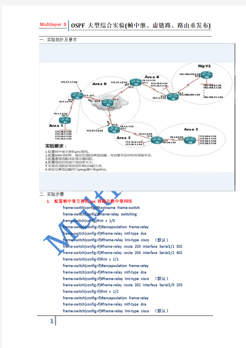

一.实验拓扑及要求
二.实验步骤
1.配置帧中继交换机pvc链路及帧中继网络
frame-swith(config)#hostname frame-switch
frame-switch(config)#frame-relay switching
frame-switch(config)#int s 1/0
frame-switch(config-if)#encapsulation frame-relay
frame-switch(config-if)#frame-relay intf-type dce
frame-switch(config-if)#frame-relay lmi-type cisco(默认)
frame-switch(config-if)#frame-relay route 203 interface Serial1/1 302
frame-switch(config-if)#frame-relay route 204 interface Serial1/2 402
frame-switch(config-if)#int s 1/1
frame-switch(config-if)#encapsulation frame-relay
frame-switch(config-if)#frame-relay intf-type dce
frame-switch(config-if)#frame-relay lmi-type cisco(默认)
frame-switch(config-if)#frame-relay route 302 interface Serial1/0 203
frame-switch(config-if)#int s 1/2
frame-switch(config-if)#encapsulation frame-relay
frame-switch(config-if)#frame-relay intf-type dce
frame-switch(config-if)#frame-relay lmi-type cisco(默认)
frame-switch(config-if)#frame-relay route 402 interface serial 1/0 204
R2(config)#int s 1/2
R2(config-if)#ip add 172.17.1.1 255.255.255.0
R2(config-if)#no shutdown
R2(config-if)#encapsulation frame-relay
R2(config-if)#no frame-relay inverse-arp
R2(config-if)#frame-relay intf-type dte(默认)
R2(config-if)#frame-relay lmi-type cisco(默认)
R2(config-if)#frame-relay map ip 172.17.1.2 203 broadcast
R2(config-if)#frame-relay map ip 172.17.1.3 204 broadcast
R3(config)#int s 1/2
R3(config-if)#ip add 172.17.1.2 255.255.255.0
R3(config-if)#no shutdown
R3(config-if)#encapsulation frame-relay
R3(config-if)#no frame-relay inverse-arp
R3(config-if)#frame-relay intf-type dte(默认)
R3(config-if)#frame-relay lmi-type cisco (默认)
R3(config-if)#frame-relay map ip 172.17.1.1 302 broadcast
R3(config-if)#frame-relay map ip 172.17.1.3 302 broadcast
R4(config)#int s 1/2
R4(config-if)#ip add 172.17.1.3 255.255.255.0
R4(config-if)#no shutdown
R4(config-if)#encapsulation frame-relay
R4(config-if)#no frame-relay inverse-arp
R4(config-if)#frame-relay intf-type dte(默认)
R4(config-if)#frame-relay lmi-type cisco (默认)
R4(config-if)#frame-relay map ip 172.17.1.1 402 broadcast
R4(config-if)#frame-relay map ip 172.17.1.2 402 broadcast
测试:
R2#show frame-relay map
Serial1/2 (up): ip 172.17.1.2 dlci 203(0xCB,0x30B0), static,
broadcast,
CISCO, status defined, active
Serial1/2 (up): ip 172.17.1.3 dlci 204(0xCC,0x30C0), static,
broadcast,
CISCO, status defined, active
R2#
R3#show frame-relay map
Serial1/2 (up): ip 172.17.1.3 dlci 302(0x12E,0x48E0), static,
broadcast,
CISCO, status defined, active
Serial1/2 (up): ip 172.17.1.1 dlci 302(0x12E,0x48E0), static,
broadcast,
CISCO, status defined, active
R3#
R4#show frame-relay map
Serial1/2 (up): ip 172.17.1.2 dlci 402(0x192,0x6420), static,
broadcast,
CISCO, status defined, active
Serial1/2 (up): ip 172.17.1.1 dlci 402(0x192,0x6420), static,
broadcast,
CISCO, status defined, active
R4#
R4#ping 172.17.1.2
Type escape sequence to abort.
Sending 5, 100-byte ICMP Echos to 172.17.1.2, timeout is 2 seconds:
!!!!!
Success rate is 100 percent (5/5), round-trip min/avg/max = 180/392/528 ms
R4#ping 172.17.1.1
Type escape sequence to abort.
Sending 5, 100-byte ICMP Echos to 172.17.1.1, timeout is 2 seconds:
!!!!!
Success rate is 100 percent (5/5), round-trip min/avg/max = 96/164/240 ms R4#
2.配置area0 区域,指定合适的dr路由器,并且要求自动形成邻居关系
R2(config)#router ospf 1
R2(config-router)#router-id 2.2.2.2
R2(config-router)#net 172.1.1.1 0.0.0.0 area 0
R3(config)#router ospf 1
R3(config-router)#router-id 3.3.3.3
R3(config-router)#net 172.17.1.2 0.0.0.0 area 0
R4(config)#router ospf 1
R4(config-router)#router-id 4.4.4.4
R4(config-router)#net 172.17.1.3 0.0.0.0 area 0
以上为ospf的基本配置,由于帧中继属于NBMA网络类型。NBMA中邻居需要手工指定,本例要求为自动形成邻居关系,且要求选定合适的路由器为dr。
具体操作如下:
R2(config-if)#ip ospf network broadcast
R3(config-if)#ip ospf network broadcast
R4(config-if)#ip ospf network broadcast
以上命令用于area0中的路由器进行dr/bdr选举,测试如下:
R2#show ip ospf neighbor
Neighbor ID Pri State Dead Time Address Interface
3.3.3.3 1 2WAY/DROTHER 00:00:30 172.17.1.2 Serial1/2
4.4.4.4 1 FULL/DR 00:00:31 172.17.1.3 Serial1/2
R2#
R3#show ip ospf neighbor
Neighbor ID Pri State Dead Time Address Interface
2.2.2.2 0 FULL/DROTHER 00:00:35 172.17.1.1 Serial1/2
R3#
R4#show ip ospf neighbor
Neighbor ID Pri State Dead Time Address Interface
2.2.2.2 0 FULL/DROTHER 00:00:36 172.17.1.1 Serial1/2
R4#
从帧中继网络连接的方式看,将router-id为4.4.4.4的路由器置为dr路由器显然是不合适,本例中适合将2.2.2.2设置为dr,具体操作如下:
R3(config-if)#ip ospf priority 0
R4(config-if)#ip ospf priority 0
测试如下:
R2#show ip ospf neighbor
Neighbor ID Pri State Dead Time Address Interface
3.3.3.3 0 FULL/DROTHER 00:00:36 172.17.1.2
Serial1/2
4.4.4.4 0 FULL/DROTHER 00:00:38 172.17.1.3
Serial1/2
R2#
R3#show ip ospf neighbor
Neighbor ID Pri State Dead Time Address Interface
2.2.2.2 1 FULL/DR 00:00:29 172.17.1.1
Serial1/2
R3#
R4#show ip ospf neighbor
Neighbor ID Pri State Dead Time Address Interface
2.2.2.2 1 FULL/DR 00:00:34 172.17.1.1
Serial1/2
R4#
注:ospf多址网络中选举dr和bdr的条件为优先级大于0且最少为2-way状态,此时可以通过将端口的优先级设置为0(接口失去选举资格自动处于drother状态)。
3.配置虚链路解决区域分割问题
R4(config-router)#area 2 virtual-link 7.7.7.7
R7(config-router)#area 2 virtual-link 4.4.4.4
测试:
R8#show ip route
Codes: C - connected, S - static, R - RIP, M - mobile, B - BGP
D - EIGRP, EX - EIGRP external, O - OSPF, IA - OSPF inter area
N1 - OSPF NSSA external type 1, N2 - OSPF NSSA external type 2
E1 - OSPF external type 1, E2 - OSPF external type 2
i - IS-IS, su - IS-IS summary, L1 - IS-IS level-1, L2 - IS-IS level-2
ia - IS-IS inter area, * - candidate default, U - per-user static route
o - ODR, P - periodic downloaded static route
Gateway of last resort is not set
172.17.0.0/24 is subnetted, 1 subnets
O IA 172.17.1.0 [110/192] via 10.1.4.1, 00:00:37, Serial1/0
172.18.0.0/32 is subnetted, 2 subnets
O IA 172.18.1.1 [110/65] via 10.1.4.1, 00:00:46, Serial1/0
O IA 172.18.0.1 [110/65] via 10.1.4.1, 00:00:46, Serial1/0
172.20.0.0/24 is subnetted, 4 subnets
C 172.20.0.0 is directly connected, Loopback0
C 172.20.1.0 is directly connected, Loopback1
C 172.20.2.0 is directly connected, Loopback2
C 172.20.3.0 is directly connected, Loopback3
10.0.0.0/24 is subnetted, 2 subnets
O IA 10.1.3.0 [110/128] via 10.1.4.1, 00:00:46, Serial1/0
C 10.1.4.0 is directly connected, Serial1/0
R8#
4.配置ospf路由汇总
ABR上的汇总:
作为区域1的abr,在r2的ospf配置模式执行
R2(config-router)#area 1 range 172.16.0.0 255.255.252.0用于汇总172.16.0.0/24、172.16.1.0/24、172.16.2.0/24、172.16.3.0/24、
作为区域2的abr,在r4的ospf配置模式执行
R4(config-router)#area 2 range 172.18.0.0 255.255.254.0用于汇总172.18.0.0/24、172.18.1.0/24
作为区域3的abr,在r7的ospf配置模式执行
R7(config-router)#area 3 range 172.20.0.0 255.255.252.0用于汇总172.20.0.0/24、172.20.1.0/24、172.20.2.0/24、172.20.3.0/24、
作为区域4的abr,在r3的ospf配置模式执行
R3(config-router)#area 4 range 172.19.0.0 255.255.254.0用于汇总172.19.0.0/24、172.19.1.0/24
ASBR上的汇总:
作为nssa区域的asbr,在路由器r5的ospf配置模式执行:R5(config-router)#summary-address 192.168.0.0 255.255.240.0用于汇总rip域中192打头的网段
测试:未汇总时路由器r8和r5上的路由表:
R8#show ip route
Codes: C - connected, S - static, R - RIP, M - mobile, B - BGP
D - EIGRP, EX - EIGRP external, O - OSPF, IA - OSPF inter area
N1 - OSPF NSSA external type 1, N2 - OSPF NSSA external type 2
E1 - OSPF external type 1, E2 - OSPF external type 2
i - IS-IS, su - IS-IS summary, L1 - IS-IS level-1, L2 - IS-IS level-2
ia - IS-IS inter area, * - candidate default, U - per-user static route
o - ODR, P - periodic downloaded static route
Gateway of last resort is not set
O E2 192.168.8.0/24 [110/1] via 10.1.4.1, 00:13:58, Serial1/0
O E2 192.168.9.0/24 [110/1] via 10.1.4.1, 00:13:58, Serial1/0
O E2 192.168.10.0/24 [110/1] via 10.1.4.1, 00:13:58, Serial1/0
172.17.0.0/24 is subnetted, 1 subnets
O IA 172.17.1.0 [110/192] via 10.1.4.1, 00:21:48, Serial1/0
172.16.0.0/32 is subnetted, 4 subnets
O IA 172.16.1.1 [110/257] via 10.1.4.1, 00:00:17, Serial1/0
O IA 172.16.0.1 [110/257] via 10.1.4.1, 00:00:17, Serial1/0
O IA 172.16.3.1 [110/257] via 10.1.4.1, 00:00:17, Serial1/0
O IA 172.16.2.1 [110/257] via 10.1.4.1, 00:00:17, Serial1/0
172.19.0.0/32 is subnetted, 2 subnets
O IA 172.19.0.1 [110/257] via 10.1.4.1, 00:01:18, Serial1/0
O IA 172.19.1.1 [110/257] via 10.1.4.1, 00:01:08, Serial1/0
172.18.0.0/32 is subnetted, 2 subnets
O IA 172.18.1.1 [110/65] via 10.1.4.1, 00:21:59, Serial1/0
O IA 172.18.0.1 [110/65] via 10.1.4.1, 00:21:59, Serial1/0
172.20.0.0/24 is subnetted, 4 subnets
C 172.20.0.0 is directly connected, Loopback0
C 172.20.1.0 is directly connected, Loopback1
C 172.20.2.0 is directly connected, Loopback2
C 172.20.3.0 is directly connected, Loopback3
O E2 192.168.11.0/24 [110/1] via 10.1.4.1, 00:13:59, Serial1/0
O E2 192.168.4.0/24 [110/1] via 10.1.4.1, 00:13:59, Serial1/0
O E2 192.168.5.0/24 [110/1] via 10.1.4.1, 00:13:59, Serial1/0
10.0.0.0/24 is subnetted, 4 subnets
O IA 10.1.3.0 [110/128] via 10.1.4.1, 00:21:59, Serial1/0
O IA 10.1.2.0 [110/256] via 10.1.4.1, 00:14:10, Serial1/0
O IA 10.1.1.0 [110/256] via 10.1.4.1, 00:14:22, Serial1/0
C 10.1.4.0 is directly connected, Serial1/0
O E2 192.168.6.0/24 [110/1] via 10.1.4.1, 00:13:59, Serial1/0
O E2 192.168.7.0/24 [110/1] via 10.1.4.1, 00:13:59, Serial1/0
O E2 192.168.255.0/24 [110/1] via 10.1.4.1, 00:13:59, Serial1/0
O E2 192.168.0.0/24 [110/1] via 10.1.4.1, 00:14:00, Serial1/0
O E2 192.168.1.0/24 [110/1] via 10.1.4.1, 00:14:00, Serial1/0
O E2 192.168.2.0/24 [110/1] via 10.1.4.1, 00:13:59, Serial1/0
O E2 192.168.3.0/24 [110/1] via 10.1.4.1, 00:13:59, Serial1/0
R8#
R5#show ip route
Codes: C - connected, S - static, R - RIP, M - mobile, B - BGP
D - EIGRP, EX - EIGRP external, O - OSPF, IA - OSPF inter area
N1 - OSPF NSSA external type 1, N2 - OSPF NSSA external type 2
E1 - OSPF external type 1, E2 - OSPF external type 2
i - IS-IS, su - IS-IS summary, L1 - IS-IS level-1, L2 - IS-IS level-2
ia - IS-IS inter area, * - candidate default, U - per-user static route
o - ODR, P - periodic downloaded static route
Gateway of last resort is not set
R 192.168.8.0/24 [120/1] via 192.168.255.2, 00:00:13, Serial1/1
R 192.168.9.0/24 [120/1] via 192.168.255.2, 00:00:13, Serial1/1
R 192.168.10.0/24 [120/1] via 192.168.255.2, 00:00:13, Serial1/1 172.17.0.0/24 is subnetted, 1 subnets
O IA 172.17.1.0 [110/128] via 10.1.2.1, 00:15:11, Serial1/0 172.16.0.0/32 is subnetted, 4 subnets
O IA 172.16.1.1 [110/193] via 10.1.2.1, 00:01:28, Serial1/0
O IA 172.16.0.1 [110/193] via 10.1.2.1, 00:01:28, Serial1/0
O IA 172.16.3.1 [110/193] via 10.1.2.1, 00:01:28, Serial1/0
O IA 172.16.2.1 [110/193] via 10.1.2.1, 00:01:28, Serial1/0 172.19.0.0/24 is subnetted, 2 subnets
C 172.19.1.0 is directly connected, Loopback1
C 172.19.0.0 is directly connected, Loopback0
172.18.0.0/32 is subnetted, 2 subnets
O IA 172.18.1.1 [110/193] via 10.1.2.1, 00:15:11, Serial1/0
O IA 172.18.0.1 [110/193] via 10.1.2.1, 00:15:11, Serial1/0 172.20.0.0/32 is subnetted, 4 subnets
O IA 172.20.1.1 [110/257] via 10.1.2.1, 00:01:14, Serial1/0
O IA 172.20.0.1 [110/257] via 10.1.2.1, 00:01:14, Serial1/0
O IA 172.20.3.1 [110/257] via 10.1.2.1, 00:01:14, Serial1/0
O IA 172.20.2.1 [110/257] via 10.1.2.1, 00:01:14, Serial1/0
R 192.168.11.0/24 [120/1] via 192.168.255.2, 00:00:14, Serial1/1
R 192.168.4.0/24 [120/1] via 192.168.255.2, 00:00:14, Serial1/1
R 192.168.5.0/24 [120/1] via 192.168.255.2, 00:00:14, Serial1/1
10.0.0.0/24 is subnetted, 4 subnets
O IA 10.1.3.0 [110/192] via 10.1.2.1, 00:15:11, Serial1/0
C 10.1.2.0 is directly connected, Serial1/0
O IA 10.1.1.0 [110/192] via 10.1.2.1, 00:15:11, Serial1/0
O IA 10.1.4.0 [110/256] via 10.1.2.1, 00:15:11, Serial1/0
R 192.168.6.0/24 [120/1] via 192.168.255.2, 00:00:14, Serial1/1
R 192.168.7.0/24 [120/1] via 192.168.255.2, 00:00:14, Serial1/1
C 192.168.255.0/24 is directly connected, Serial1/1
R 192.168.0.0/24 [120/1] via 192.168.255.2, 00:00:14, Serial1/1
R 192.168.1.0/24 [120/1] via 192.168.255.2, 00:00:14, Serial1/1
R 192.168.2.0/24 [120/1] via 192.168.255.2, 00:00:14, Serial1/1
R 192.168.3.0/24 [120/1] via 192.168.255.2, 00:00:14, Serial1/1
R5#
汇总后:
R8#show ip route
Codes: C - connected, S - static, R - RIP, M - mobile, B - BGP
D - EIGRP, EX - EIGRP external, O - OSPF, IA - OSPF inter area
N1 - OSPF NSSA external type 1, N2 - OSPF NSSA external type 2
E1 - OSPF external type 1, E2 - OSPF external type 2
i - IS-IS, su - IS-IS summary, L1 - IS-IS level-1, L2 - IS-IS level-2
ia - IS-IS inter area, * - candidate default, U - per-user static route
o - ODR, P - periodic downloaded static route
Gateway of last resort is not set
172.17.0.0/24 is subnetted, 1 subnets
O IA 172.17.1.0 [110/192] via 10.1.4.1, 00:52:29, Serial1/0 172.16.0.0/22 is subnetted, 1 subnets
O IA 172.16.0.0 [110/257] via 10.1.4.1, 00:02:17, Serial1/0 172.19.0.0/23 is subnetted, 1 subnets
O IA 172.19.0.0 [110/257] via 10.1.4.1, 00:23:02, Serial1/0 172.18.0.0/16 is variably subnetted, 3 subnets, 2 masks
O IA 172.18.1.1/32 [110/65] via 10.1.4.1, 00:52:39, Serial1/0
O IA 172.18.0.0/23 [110/193] via 10.1.4.1, 00:07:02, Serial1/0
O IA 172.18.0.1/32 [110/65] via 10.1.4.1, 00:52:39, Serial1/0 172.20.0.0/24 is subnetted, 4 subnets
C 172.20.0.0 is directly connected, Loopback0
C 172.20.1.0 is directly connected, Loopback1
C 172.20.2.0 is directly connected, Loopback2
C 172.20.3.0 is directly connected, Loopback3
10.0.0.0/24 is subnetted, 4 subnets
O IA 10.1.3.0 [110/128] via 10.1.4.1, 00:52:39, Serial1/0
O IA 10.1.2.0 [110/256] via 10.1.4.1, 00:44:50, Serial1/0
O IA 10.1.1.0 [110/256] via 10.1.4.1, 00:45:02, Serial1/0
C 10.1.4.0 is directly connected, Serial1/0
O E2 192.168.255.0/24 [110/1] via 10.1.4.1, 00:44:40, Serial1/0
O E2 192.168.0.0/20 [110/1] via 10.1.4.1, 00:18:17, Serial1/0
R8#
R5#show ip route
Codes: C - connected, S - static, R - RIP, M - mobile, B - BGP
D - EIGRP, EX - EIGRP external, O - OSPF, IA - OSPF inter area
N1 - OSPF NSSA external type 1, N2 - OSPF NSSA external type 2
E1 - OSPF external type 1, E2 - OSPF external type 2
i - IS-IS, su - IS-IS summary, L1 - IS-IS level-1, L2 - IS-IS level-2
ia - IS-IS inter area, * - candidate default, U - per-user static route
o - ODR, P - periodic downloaded static route
Gateway of last resort is not set
R 192.168.8.0/24 [120/1] via 192.168.255.2, 00:00:15, Serial1/1
R 192.168.9.0/24 [120/1] via 192.168.255.2, 00:00:15, Serial1/1
R 192.168.10.0/24 [120/1] via 192.168.255.2, 00:00:15, Serial1/1 172.17.0.0/24 is subnetted, 1 subnets
O IA 172.17.1.0 [110/128] via 10.1.2.1, 00:44:56, Serial1/0 172.16.0.0/22 is subnetted, 1 subnets
O IA 172.16.0.0 [110/193] via 10.1.2.1, 00:02:33, Serial1/0 172.19.0.0/24 is subnetted, 2 subnets
C 172.19.1.0 is directly connected, Loopback1
C 172.19.0.0 is directly connected, Loopback0
172.18.0.0/16 is variably subnetted, 3 subnets, 2 masks
O IA 172.18.1.1/32 [110/193] via 10.1.2.1, 00:44:56, Serial1/0
O IA 172.18.0.0/23 [110/193] via 10.1.2.1, 00:07:16, Serial1/0
O IA 172.18.0.1/32 [110/193] via 10.1.2.1, 00:44:56, Serial1/0 172.20.0.0/22 is subnetted, 1 subnets
O IA 172.20.0.0 [110/257] via 10.1.2.1, 00:09:57, Serial1/0
R 192.168.11.0/24 [120/1] via 192.168.255.2, 00:00:15, Serial1/1
R 192.168.4.0/24 [120/1] via 192.168.255.2, 00:00:15, Serial1/1
R 192.168.5.0/24 [120/1] via 192.168.255.2, 00:00:15, Serial1/1
10.0.0.0/24 is subnetted, 4 subnets
O IA 10.1.3.0 [110/192] via 10.1.2.1, 00:44:56, Serial1/0
C 10.1.2.0 is directly connected, Serial1/0
O IA 10.1.1.0 [110/192] via 10.1.2.1, 00:44:56, Serial1/0
O IA 10.1.4.0 [110/256] via 10.1.2.1, 00:44:56, Serial1/0
R 192.168.6.0/24 [120/1] via 192.168.255.2, 00:00:15, Serial1/1
R 192.168.7.0/24 [120/1] via 192.168.255.2, 00:00:15, Serial1/1
C 192.168.255.0/24 is directly connected, Serial1/1
R 192.168.0.0/24 [120/1] via 192.168.255.2, 00:00:15, Serial1/1
R 192.168.1.0/24 [120/1] via 192.168.255.2, 00:00:15, Serial1/1
R 192.168.2.0/24 [120/1] via 192.168.255.2, 00:00:15, Serial1/1
R 192.168.3.0/24 [120/1] via 192.168.255.2, 00:00:15, Serial1/1
O 192.168.0.0/20 is a summary, 00:18:37, Null0
R5#
5.采用合适的区域类型,来限制lsa的泛洪
1.将区域1设置为末梢区域或是完全末梢区域
R2(config-router)#area 1 stub
R1(config-router)#area 1 stub
配置前:路由表和ospf database的简要信息
R1#show ip route
172.17.0.0/24 is subnetted, 1 subnets
O IA 172.17.1.0 [110/128] via 10.1.1.2, 00:00:07, Serial1/1
172.16.0.0/24 is subnetted, 4 subnets
172.19.0.0/23 is subnetted, 1 subnets
O IA 172.19.0.0 [110/193] via 10.1.1.2, 00:00:07, Serial1/1
172.18.0.0/16 is variably subnetted, 3 subnets, 2 masks O IA 172.18.1.1/32 [110/193] via 10.1.1.2, 00:00:07, Serial1/1
O IA 172.18.0.0/23 [110/193] via 10.1.1.2, 00:00:07, Serial1/1
O IA 172.18.0.1/32 [110/193] via 10.1.1.2, 00:00:07, Serial1/1 172.20.0.0/22 is subnetted, 1 subnets
O IA 172.20.0.0 [110/257] via 10.1.1.2, 00:00:08, Serial1/1
10.0.0.0/24 is subnetted, 4 subnets
O IA 10.1.3.0 [110/192] via 10.1.1.2, 00:00:08, Serial1/1
O IA 10.1.2.0 [110/192] via 10.1.1.2, 00:00:08, Serial1/1
C 10.1.1.0 is directly connected, Serial1/1
O IA 10.1.4.0 [110/256] via 10.1.1.2, 00:00:08, Serial1/1
O E2 192.168.255.0/24 [110/1] via 10.1.1.2, 00:00:08, Serial1/1
O E2 192.168.0.0/20 [110/1] via 10.1.1.2, 00:00:08, Serial1/1
R1#show ip ospf database
Summary Net Link States (Area 1)
Link ID ADV Router Age Seq# Checksum 10.1.2.0 2.2.2.2 58 0x80000003 0x00A9FB 10.1.3.0 2.2.2.2 58 0x80000003 0x009E06 10.1.4.0 2.2.2.2 58 0x80000003 0x00164D 172.17.1.0 2.2.2.2 58 0x80000003 0x002F05 172.18.0.0 2.2.2.2 58 0x80000003 0x00B53E 172.18.0.1 2.2.2.2 58 0x80000003 0x00B041 172.18.1.1 2.2.2.2 58 0x80000003 0x00A54B 172.19.0.0 2.2.2.2 58 0x80000002 0x00AB48 172.20.0.0 2.2.2.2 58 0x80000003 0x00169D
Summary ASB Link States (Area 1)
Link ID ADV Router Age Seq# Checksum 5.5.5.5 2.2.2.2 58 0x80000001 0x005D42
Type-5 AS External Link States
Link ID ADV Router Age Seq# Checksum Tag 192.168.0.0 5.5.5.5 140 0x80000001 0x0095AF 0 192.168.255.0 5.5.5.5 140 0x80000001 0x00E055 0
R1#
配置后:
R1#show ip route
172.17.0.0/24 is subnetted, 1 subnets
O IA 172.17.1.0 [110/128] via 10.1.1.2, 00:03:24, Serial1/1
172.16.0.0/24 is subnetted, 4 subnets
172.18.0.0/16 is variably subnetted, 3 subnets, 2 masks
O IA 172.18.1.1/32 [110/193] via 10.1.1.2, 00:03:24, Serial1/1
O IA 172.18.0.0/23 [110/193] via 10.1.1.2, 00:03:24, Serial1/1
O IA 172.18.0.1/32 [110/193] via 10.1.1.2, 00:03:24, Serial1/1 172.20.0.0/22 is subnetted, 1 subnets
O IA 172.20.0.0 [110/257] via 10.1.1.2, 00:03:24, Serial1/1
10.0.0.0/24 is subnetted, 4 subnets
O IA 10.1.3.0 [110/192] via 10.1.1.2, 00:03:25, Serial1/1
O IA 10.1.2.0 [110/192] via 10.1.1.2, 00:03:25, Serial1/1
C 10.1.1.0 is directly connected, Serial1/1
O IA 10.1.4.0 [110/256] via 10.1.1.2, 00:03:25, Serial1/1
O*IA 0.0.0.0/0 [110/65] via 10.1.1.2, 00:03:25, Serial1/1
R1#show ip ospf database
OSPF Router with ID (1.1.1.1) (Process ID 1)
Summary Net Link States (Area 1)
Link ID ADV Router Age Seq# Checksum 0.0.0.0 2.2.2.2 16 0x80000001 0x0075C0 10.1.2.0 2.2.2.2 16 0x80000004 0x00C5E0 10.1.3.0 2.2.2.2 16 0x80000004 0x00BAEA 10.1.4.0 2.2.2.2 16 0x80000004 0x003232 172.17.1.0 2.2.2.2 16 0x80000004 0x004BE9 172.18.0.0 2.2.2.2 16 0x80000004 0x00D123 172.18.0.1 2.2.2.2 16 0x80000004 0x00CC26 172.18.1.1 2.2.2.2 16 0x80000004 0x00C130 172.19.0.0 2.2.2.2 16 0x80000003 0x00C72D 172.20.0.0 2.2.2.2 16 0x80000004 0x003282 R1#
2.将区域1设置为完全末梢区域
R2(config-router)#area 1 stub no-summary
R1(config-router)#area 1 stub
配置后:
R1#show ip route
O*IA 0.0.0.0/0 [110/65] via 10.1.1.2, 00:04:23, Serial1/1
Summary Net Link States (Area 1)
Link ID ADV Router Age Seq# Checksum
0.0.0.0 2.2.2.2 289 0x80000003 0x0071C2
R1#
3.由于路由器r5连接ospf自治域和rip域,而r5处于ospf的区域4中(非骨干
区域)此时屈原不能作为末梢网络,将区域4设置为nssa,这样可以将rip域内的路由通告到ospf中。
R5(config-router)#area 4 nssa
R3(config-router)#area 4 nssa
6.保证任意路由可以ping通所有路由器
在r5上将rip重发布到ospf中,并向rip域内通告一条默认路由
R5(config)#router ospf 1
R5(config-router)#redistribute rip subnets metric 1
R5(config-router)#default-information originate
测试:
R1#ping 192.168.1.1
Type escape sequence to abort.
Sending 5, 100-byte ICMP Echos to 192.168.1.1, timeout is 2 seconds:
!!!!!
Success rate is 100 percent (5/5), round-trip min/avg/max = 148/244/296 ms
R1#ping 172.20.1.1
Type escape sequence to abort.
Sending 5, 100-byte ICMP Echos to 172.20.1.1, timeout is 2 seconds:
!!!!!
Success rate is 100 percent (5/5), round-trip min/avg/max = 116/285/412 ms
R1#
R8#ping 192.168.3.1
Type escape sequence to abort.
Sending 5, 100-byte ICMP Echos to 192.168.3.1, timeout is 2 seconds:
!!!!!
Success rate is 100 percent (5/5), round-trip min/avg/max = 384/458/524 ms
R8#ping 172.16.0.1
Type escape sequence to abort.
Sending 5, 100-byte ICMP Echos to 172.16.0.1, timeout is 2 seconds:
!!!!!
Success rate is 100 percent (5/5), round-trip min/avg/max = 156/206/268 ms R8#
三.设置配置文件保存
R1#show running-config
Building configuration...
Current configuration : 1509 bytes
!
! Last configuration change at 16:08:56 UTC Tue Mar 8 2011
!
version 12.4
service timestamps debug datetime msec
service timestamps log datetime msec
no service password-encryption
!
hostname R1
!
boot-start-marker
boot-end-marker
!
!
no aaa new-model
memory-size iomem 5
!
!
ip cef
no ip domain lookup
!
!
ip auth-proxy max-nodata-conns 3
ip admission max-nodata-conns 3
!
multilink bundle-name authenticated
!
!
!
!
!
!
!
!
!
!
!
!
!
!
archive
log config
hidekeys
!
!
!
!
!
!
!
!
interface Loopback0
ip address 172.16.0.1 255.255.255.0 !
interface Loopback1
ip address 172.16.1.1 255.255.255.0 !
interface Loopback2
ip address 172.16.2.1 255.255.255.0 !
interface Loopback3
ip address 172.16.3.1 255.255.255.0 !
interface FastEthernet0/0
no ip address
shutdown
duplex auto
speed auto
!
interface FastEthernet0/1
no ip address
shutdown
duplex auto
speed auto
!
interface Serial1/0
no ip address
shutdown
serial restart-delay 0
!
interface Serial1/1
ip address 10.1.1.1 255.255.255.0 serial restart-delay 0
!
interface Serial1/2
no ip address
shutdown
serial restart-delay 0
!
interface Serial1/3
no ip address
shutdown
serial restart-delay 0
!
router ospf 1
router-id 1.1.1.1
log-adjacency-changes
area 1 stub
network 10.1.1.1 0.0.0.0 area 1 network 172.16.0.0 0.0.255.255 area 1 !
ip http server
no ip http secure-server
!
ip forward-protocol nd
!
!
!
!
!
!
control-plane
!
!
!
!
!
!
!
!
!
line con 0
exec-timeout 0 0
logging synchronous
line aux 0
line vty 0 4
!
!
end
R1#
R2#show run
Building configuration...
Current configuration : 1537 bytes
!
! Last configuration change at 16:26:23 UTC Tue Mar 8 2011 !
version 12.4
service timestamps debug datetime msec
service timestamps log datetime msec
no service password-encryption
!
hostname R2
!
boot-start-marker
boot-end-marker
!
!
no aaa new-model
memory-size iomem 5
!
!
ip cef
no ip domain lookup
!
!
ip auth-proxy max-nodata-conns 3
ip admission max-nodata-conns 3
!
multilink bundle-name authenticated !
!
!
!
!
!
!
!
!
!
!
!
!
!
archive
log config
hidekeys
!
!
!
!
!
!
!
!
interface FastEthernet0/0
no ip address
shutdown
duplex auto
speed auto
!
interface FastEthernet0/1
no ip address
shutdown
duplex auto
speed auto
!
interface Serial1/0
ip address 10.1.1.2 255.255.255.0
serial restart-delay 0
!
interface Serial1/1
no ip address
shutdown
serial restart-delay 0
!
interface Serial1/2
ip address 172.17.1.1 255.255.255.0 encapsulation frame-relay
ip ospf network broadcast
serial restart-delay 0
frame-relay map ip 172.17.1.3 204 broadcast frame-relay map ip 172.17.1.2 203 broadcast no frame-relay inverse-arp
!
interface Serial1/3
no ip address
shutdown
serial restart-delay 0
!
router ospf 1
router-id 2.2.2.2
log-adjacency-changes
area 1 stub no-summary
area 1 range 172.16.0.0 255.255.252.0 network 10.1.1.2 0.0.0.0 area 1
network 172.1.1.1 0.0.0.0 area 0
network 172.17.1.1 0.0.0.0 area 0
!
ip http server
no ip http secure-server
!
ip forward-protocol nd
!
!
!
!
!
!
control-plane
OSPF实验4:虚链路
OSPF实验4:虚链路 实验等级:Professional 实验拓扑: 实验分析: 上面这个网络的设计在OSPF中是比较失败的,因为OSPF建议所有的非骨干区域都和骨干区域直连。上面这个网络的设计将会导致Area2的数据和Area0无法通信。为了解决这个问题,一种方法可以在R3和R1上增加一条物理链路。还有一种过渡的方法就是使用虚链路。 实验基本配置: R1: interface Loopback0 ip address 1.1.1.1 255.255.255.0 ip ospf network point-to-point ! interface Serial1/0 ip address 10.1.1.1 255.255.255.0 serial restart-delay 0 ! router ospf 10
router-id 1.1.1.1 log-adjacency-changes network 10.1.1.0 0.0.0.255 area 0 R2: interface Loopback0 ip address 2.2.2.2 255.255.255.0 ! interface Serial1/0 ip address 10.1.1.2 255.255.255.0 serial restart-delay 0 ! interface Serial1/1 ip address 11.1.1.1 255.255.255.0 serial restart-delay 0 ! router ospf 10 router-id 2.2.2.2 log-adjacency-changes network 10.1.1.0 0.0.0.255 area 0 network 11.1.1.0 0.0.0.255 area 1 R3: interface Loopback0 ip address 3.3.3.3 255.255.255.0 ! interface Serial1/0 ip address 11.1.1.2 255.255.255.0 serial restart-delay 0 ! router ospf 10 router-id 3.3.3.3 log-adjacency-changes network 3.3.3.0 0.0.0.255 area 2 network 11.1.1.0 0.0.0.255 area 1 我们在R1上查看路由表,发现没有R3的Loopback接口路由: R1#sho ip rou Codes: C - connected, S - static, R - RIP, M - mobile, B - BGP D - EIGRP, EX - EIGRP external, O - OSPF, IA - OSPF inter area N1 - OSPF NSSA external type 1, N2 - OSPF NSSA external type 2 E1 - OSPF external type 1, E2 - OSPF external type 2 i - IS-IS, su - IS-IS summary, L1 - IS-IS level-1, L2 - IS-IS level-2
H3C常见的OSPF
1. OSPF邻接形成过程? 互发HELLO包,形成双向通信 根据接口网络类型选DR/BDR 发第一个DBD,选主从 进行DBD同步 交互LSR、LSU、LSack进行LSA同步 同步结束后进入FULL 2. OSPF中承载完整的链路状态的包?LSU 3. 链路状态协议和距离矢量协议的比较? (1)路由传递方法不同(2)收敛速度不同(3)度量值不同(4)有环无环 (5)应用环境不同(6)有无跳数限制(7)生成路由的算法不同(8)对设备资源的消耗不同 4. OSPF防环措施? (1)SFP算法无环(2)更新信息中携始发者信息,并且为一手信息(3)多区域时要求非骨干区域,必须连接骨干区域,才能互通路由,防止了始发者信息的丧失,避免了环路。 5. OSPF是纯链路状态的协议吗? (1)单区域时是纯的链路状态协议,而多区域时,区域间路由使用的是距离矢量算法。6. OSPF中DR选举的意义?DR选举时的网络类型?DR和其它路由器的关系? (1)提高LSA同步效率。(2)广播型和NBMA要选DR (3)DR与其它路由器为邻接关系。 7. OSPF的NSSA区域和其它区域的区别? 比普通区域相比:去除了四类五类LSA,增加了七类LSA 和STUB区域相比:他可以单向引入外部路由 8. OSPF的LSA类型,主要由谁生成? 一类路由器LSA 所有路由器本区域描述直连拓扑信息 二类网络LSA DR 本区域描述本网段的掩码和邻居 三类网络汇总LSA ABR 相关区域区域间的路由信息 四类ASBR汇总LSA ABR 相关区域去往ASBR的一条路由信息 五类外部LSA ASBR 整个AS AS外部的路由信息 七类NSSA外部LSA ASBR 本NSSA区域AS外部的路由信息 9. IBGP为什么采用全互联?不采用全互联怎么部署? (1)解决IBGP水平分割问题(2)反射器或联盟 10. 路由反射器的反射原则? (1)客户端的路由反射给所有邻居(2)非客户端的路由反射给客户端(3)只发最优路由(4)两个非客户端路由不能互通(5)反射不改变路由属性 11. OSPF邻居形成过程? 12. OSPF有几类LSA? 13. OSPF的NSSA区域与其它区域的通信方法? 14. PPP协商过程? 15. OSPF没有形成FULL状态的原因? (1)HELLO和失效时间不一致(2)接口网络类型不一致(3)区域不一致(4)MA网络中掩码不一致(5)版本不一致(6)认证不通过(7)ROUTER-ID 相同(8)MA网络中优先级都为0 (9)MTU不一致(10)特殊区域标记不一样(11)底层不通(12)NBMA网络中没有指邻居
实验五 OSPF的基本配置
实验五OSPF的基本配置 实验拓扑图 1.基本配置 R1(config)#interface fastEthernet 0/0 R1(config-if)#ip address 172.16.1.1 255.255.255.0 R1(config-if)#no shutdown R1(config)#interface s2/0 R1(config-if)#ip add 192.168.1.5 255.255.255.252 R1(config-if)#clock rate 64000 R1(config-if)#no shutdown R2(config)#interface s3/0 R2(config-if)#ip add 192.168.1.6 255.255.255.252 R2(config-if)#no shutdown R2(config)#interface fa1/0 R2(config-if)#ip add 10.10.10.1 255.255.255.0 R2(config-if)#no shutdown 2.OSPF的配置 R1(config)#router ospf 1 启动ospf进程,进程ID为1(进程ID取值范围是1-65535中的一个整数),此进程号只是本地的一个标识,具有本地意义,与同一个区域中的OSPF路由器进程号没有关系,进程号不同不影响邻接关系的建立。 R1(config-router)#network 172.16.1.0 0.0.0.255 area 0 宣告网络,即定义参与OSPF进程的接口或网络,并指定其运行的区域(区域0为骨干区域),通配符掩码用来控制要宣告的范围,任何在此地址范围内的接口都运行OSPF协议,发送和接收OSPF报文,0表示精确匹配,将检查匹配地址中对应位,1表示任意匹配,不检查匹配地址中对应位。 R1(config-router)#network 192.168.1.4 0.0.0.3 area 0 R2(config)#router ospf 1 R2(config-router)#network 192.168.1.4 0.0.0.3 area 0 R2(config-router)#network 10.10.10.0 0.0.0.255 area 0 3.查看信息 (1)查看路由表 R1#show ip route 要求对R1路由表截图,说明OSPF路由的含义
OSPF虚链路认证
OSPF域间汇总 实验目的:了解并掌握域间汇总的配置 实验拓扑图: 基本配置 R1(config)#int s2/1 R1(config-if)#ip ad 12.0.0.1 255.255.255.0 R1(config-if)#int lo 0 R1(config-if)#ip ad 1.1.0.1 255.255.255.0 R1(config-if)#int lo 1 R1(config-if)#ip ad 1.1.1.1 255.255.255.0 R1(config-if)#int lo 2 R1(config-if)#ip ad 1.1.2.1 255.255.255.0 R1(config-if)#int lo 3 R1(config-if)#ip ad 1.1.3.1 255.255.255.0 R1(config-if)#int s2/1 R1(config-if)#no sh R1(config-if)# 00:02:54: %LINK-3-UPDOWN: Interface Serial2/1, changed state to up R1(config-if)# 00:02:55: %LINEPROTO-5-UPDOWN: Line protocol on Interface Serial2/1, changed state to up R1(config-if)#router ospf 10 R1(config-router)#net 12.0.0.0 0.0.0.255 a 0 R1(config-router)#no net 12.0.0.0 0.0.0.255 a 0 R1(config-router)#net 12.0.0.0 0.0.0.255 a 1 R1(config-router)#net 1.1.0.0 0.0.0.255 a 1 R1(config-router)#net 1.1.1.0 0.0.0.255 a 1 R1(config-router)#net 1.1.2.0 0.0.0.255 a 1 R1(config-router)#net 1.1.3.0 0.0.0.255 a 1 R2(config)#int s2/1
解决OSPF不连续区域的3种方法
解决OSPF不连续区域的3种方法 网络拓扑图 解决OSPF不连续区域的问题我们有三种解决办法: 1.多进程双向重新分布 2.创建tunnel通道宣告到区域0 3.创建虚链路 以下是3种方法配置的详细命令: 方法1:多进程双向重新分布 (1).重新启动另外一个OSPF进程 (2).在2个OSPF进程中宣告不连续的网段
(3).双向发布OSPF进程: redistribute ospf 进程号 subnets R1 int s0/0 ip add 1.1.1.1 255.255.255.0 no shut router ospf 110 router-id 1.1.1.1 network 1.1.1.0 0.0.0.255 area 0 R2 int s0/0 ip add 1.1.1.2 255.255.255.0 no shut int s0/1 ip add 2.2.2.1 255.255.255.0 no shut
router ospf 110 router-id 2.2.2.2 network 2.2.2.0 0.0.0.255 area 1 network 1.1.1.0 0.0.0.255 area 0 router ospf 120 router-id 2.2.2.5 network R3 int s0/0 ip add 2.2.2.2 255.255.255.0 no shut int s0/1 ip add 3.3.3.1 255.255.255.0 no shut router ospf 110 router-id 3.3.3.3
ospf虚链路的配置实验
ospf虚链路的配置实验 一、目的:Area 2经过Area 1与Area 0之间建立虚链路. 此拓扑中,virtual-link在R4与R2之间建立,从而使得Area 2与Area 0之间进行直接连接,virtual-link配置在R2与R4实施。通过实验,R4就变成一个特别的ABR。virtual-link 上面转发的是LSA – 3。 二、思想:R2与R4路由器互指对方的Router-ID。 三、问题:如何确认虚连接的对端IP地址? 中间连接area 0的过渡area 1上的ABR之间存在lsa-1与lsa-2的传递,确认对端的IP 地址。通过邻居地址指定, R2上的邻接状态: R4上的邻接状态:
四、配置内容: 4.1、R2: sh ip ospf database self-originate 可以看到Summary Net Link States 。 注意R2是个ABR,它的一个接口连接Area 0,另一个接口连接Area 1,所以R2会产生两区域的Summary Net Link States (lsa-3),通过Summary Net Link States (Area 0)中可以看到R2把23.1.1.0与34.1.1.0网段Upward(转发)到Area 0中;把1.1.1.0与12.1.1.0网段Upward(转发)到Area 1中,使得Area 0与Area 1中都有相互之间的路由,从而23.1.1.0、34.1.1.0 、1.1.1.0、12.1.1.0网段之间互通。
4.2、R4: R4为什么说是一个特殊的ABR呢?通过Virtual-Link 后,R4跨了Area 0, Area 1、Area 2三个区域,R4把学习到相关网段进行汇总,然后分发到了不同区域中。 Summary Net Link States (Area 1): R4把源Area 2中的5.5.5.0、45.1.1.0网段Upward到Area 1。 Summary Net Link States (Area 0): 由于R4与R2建立了Virtual-Link,R2的一个口在Area 1中,R4自然也就学习到了源Area 1中的23.1.1.0、34.1.1.0网段,同样也通过Virtual-link,R4把5.5.5.0、45.1.1.0、23.1.1.0、34.1.1.0网段Upward到了Area 0中。在此,有同学要问,那么不是和R2宣告进Area 0中的23.1.1.0、34.1.1.0网段重复了吗?跨了三Area 的特殊性就体现在这里! 同理,通过R2与R4之间的virtual-link,R4把源Area 0与Area 1中的路由信息汇总传递到Area 2中。 五、小结: 由于R4通过Virtual-Link横跨了area 0,area 1,area 2三个区域,那么把Area 0、Area 1区域中的路由信息通过Area 1传递给了Area 2,把Area 1、Area 2 传递给了Area 0,通过配置Virtual-Link,Area 2 就与Area 0进行直连。
思科OSPF实验1:基本的OSPF配置
思科OSPF实验1:基本的OSPF配置 实验步骤: 1.首先在3台路由器上配置物理接口,并且使用ping命令确保物理链路的畅通。 2.在路由器上配置loopback接口: R1(config)#int loopback 0 R1(config-if)#ip add 1.1.1.1 255.255.255.0 R2(config)#int loopback 0 R2(config-if)#ip add 2.2.2.2 255.255.255.0 R3(config)#int loopback 0 R3(config-if)#ip add 3.3.3.3 255.255.255.0 路由器的RID是路由器接口的最高的IP地址,当有环回口存在是,路由器将使用环回口的最高IP地址作为起RID,从而保证RID的稳定。 3.在3台路由器上分别启动ospf进程,并且宣告直连接口的网络。 R1(config)#router ospf 10 R1(config-router)#network 192.168.1.0 0.0.0.255area 0 R1(config-router)#network 1.1.1.0 0.0.0.255 area 0 R1(config-router)#network 192.168.3.0.0.0.255 area 0
ospf的进程号只有本地意义,既在不同路由器上的进程号可以不相同。但是为了日后维护的方便,一般启用相同的进程号。 ospf使用反向掩码。Area 0表示骨干区域,在设计ospf网络时,所有的非骨干区域都需要和骨干区域直连! R2,R3的配置和R1类似,这里省略。不同的是我们在R2和R3上不宣告各自的环回口。 *Aug 13 17:58:51.411: %OSPF-5-ADJCHG: Process 10, Nbr 2.2.2.2 on Serial1/0 from LOADING to FULL, Loading Done 配置结束后,我们可以看到邻居关系已经到达FULL状态。 4. 在R1上查看路由表,可以看到以下信息: R1#show ip route Codes: C - connected, S - static, R - RIP, M - mobile, B - BGP D - EIGRP, EX - EIGRP external, O - OSPF, IA - OSPF inter area N1 - OSPF NSSA external type 1, N2 - OSPF NSSA external type 2 E1 - OSPF external type 1, E2 - OSPF external type 2 i - IS-IS, su - IS-IS summary, L1 - IS-IS level-1, L2 - IS-IS level-2 ia - IS-IS inter area, * - candidate default, U - per-user static route o - ODR, P - periodic downloaded static route Gateway of last resort is not set 1.0.0.0/24 is subnetted, 1 subnets
OSPF各种数据包结构解析
OSPF Packet Header OSPF报头为24字节. Version OSPF的版本号.IPv4为OSPFv2,IPv6为OSPFv3. Type OSPF数据包类型. Packet Length OSPF数据包长度. Router ID 始发OSPF数据包的路由器的Router-ID. Area ID 始发OSPF数据包的路由器接口所在的区域. Checksum OSPF数据包的校验和. AuType OSPF认证类型. Authentication AuType为0,不检查该字段. AuType为1,包含最长为64bit的口令. AuType为2,包含Key-ID,消息摘要和不减小的加密序列号. Authentication Data Length 附加在OSPF数据包尾部的消息摘要长度. Cryptographic Sequence Number 一个不会减小的序列号,用于防重放攻击. OSPF Hello Packet Hello包用于建立和维护邻接关系,也在MA网络中选举DR/BDR. *Network Mask 发送数据包的接口的网络掩码,必须匹配. *Hello Interval 接口上发送Hello包的时间间隔,BMA和P2P网络中默认为10s,NBMA网络中默认为30s. *Options DN MPLS VPN使用. O 用于Opaque LSA. DC按需链路上使用 EA 接收和转发具有外部属性LSA的能力. N/P N为1表明支持NSSA LSA,N为0表明不接收和发送NSSA. P(Propagation)为1执行7类到5类LSA转换,P为0不执行转换. MC MOPSF中使用. E E为1接收5类LSA,E为0不接收5类LSA. MT MT-OSPF使用. Router Priority 接口优先级,用于选举DR/BDR.为0将不参与选举,默认接口优先级为1. *Router Dead Interval 将邻居视为down前等待Hello包的时间间隔,默认为Hello Interval的4倍. Designated Router MA网络中的DR接口的IP地址,如果不存在将设置为 Backup Designated Router MA网络中的BDR接口的IP地址,如果不存在将设置为Neighbor 列出了始发路由器保存的邻居列表. * 必须匹配才可建立OSPF邻接关系. OSPF DBD Packet DBD中包含LSA头部信息,用于选举Master/Slave路由器,同步LSDB. Interface MTU 始发路由器接口可发送的最大IP数据包大小,在虚链路上传送时设置为0x0000. I Initial,发送是第一个DBD包时设置为1,后续DBD包设置为0. M More,发送不是最后一个DBD包时,设置为1,如果是最后一个DBD包设置为0. MS Master/Slave,如果设置为1代表是Master路由器,设置为0代表是Slave路由器. DD Sequence Number DBD包的序列号由Master路由器设置.
OSPF邻居及邻接关系(虚链路)置案例
一、技术概述 OSPF网络中,所有路由信息都在邻居或邻接中传递、交换。通过维持邻居或邻接关系,对整网的稳定性起着重要作用。 本节将重点研究ospf的网络类型及邻居邻接关系。 。 二、网络拓扑: 三、相关知识点总结: 1. 邻居关系和邻接关系有什么区别? 邻居关系和邻接关系是不同的概念。 邻居关系是指,当双方收到对方的hello报文的时候,报文里面的参数(hello time.dead interval , area id.authentication ,mask 等)一致的时候,并且邻居关系为2-way的时候,这个就可以成为是建立了邻居关系,但是还不是邻接关系。 邻接关系是指在建立的邻居关系之后继续发送DD,LSR,LSU等报文,最终双方的LSDB达到同步之后,邻居状态为FULL时,才成为邻接关系。 希望对你希望对你有用。 2. OSPF支持的网络类型有哪些? ospf的网络类型:根据链路层协议判断网络类型 1)、point to point----ppp 2)、广播-----以太网Ethernet 3)、NBMA FR (frame-relay)帧中继物理结构与广播很像,但是该网络默认不传递广播 4)、点到多点,从NBMA修改过来的。(可看作点到点类型网络) 3. 什么是DR和BDR?
选举DR和BDR:DR为指定路由器,BDR为备份路由器。 4. 哪些网络需要进行选举DR、BDR ?为什么要进行DR/BDR选举? 广播和BMA类型的网络都会选举DR和BDR,NBMA为人为指定。 判断该链路上是否有DR(先启动的) 根据接口优先级和route-ID选举。优先级默认为1,范围1---255,先判断优先级,若一致,选route-ID大的,最优的为DR,次之为BDR。每次评选选BDR。如果网络中路由器很多时,那么需要维护的建立的邻接关系就很多,需要发送的报文也很多。而且每台路由器之间都相互发送lsa,这样就造成好多重复的lsa在网络中传递,浪费了太多带宽资源,所以选取dr 和bdr用来节省带宽资源。 5. Router Priority最大的一定是DR吗? 不一定,选择完成后的特性: 终身制: 世袭制: 民主制:优先级培认为置为0,则没有选举权。 所有的路由器包括DR、BDR、DR-other之间的关系:所偶的DR-other和BDR时 及drDR之间会形成full,DR-other之间只能为tow-way。 6. 配置虚连接的时候如何表示对端路由器? 四、项目需求: 1. 如图所示,配置OSPF多区域后,由于area 2 和area 0 没有直接相连,故所以,在area 1里配置虚电路,使得R4可以收到R1的路由信息。 2. 区域零中使r3永远为DR,区域1和区域2中,不进行DR/BDR选举,以加快收敛 3. 所有的互联地址以192.168.255.0/24主类地址进行以/30规划,且在R3上看到去往r4直连网络的路由开销为100,r4到R3的直连网络路由为50. R1: sysname llb-R1 interface GigabitEthernet0/0/0 ip address 192.168.255.1 255.255.255.252 ospf network-type p2p interface LoopBack0 ip address 1.1.1.1 255.255.255.255 # ospf 1 router-id 1.1.1.1 area 0.0.0.0
配置OSPF虚连接
实验报告 实验人:学号:日期:2015/3/29 院(系):专业(班级):网络工程 实验题目:配置OSPF虚连接 一. 实验目的 1. 掌握OSPF的相关理论知识,了解OSPF虚连接的原理; 2. 掌握OSPF虚连接配置的相关命令; 二. 实验原理 虚连接(Virtual-link):由于网络的拓扑结构复杂,有时无法满足每个区域必须和骨干区域直接相连的要求,为解决此问题,OSPF提出了虚链路的概念。 虚连接是设置在两个路由器之间,这两个路由器都有一个端口与同一个非主干区域相连。虚连接被认为是属于主干区域的,在OSPF路由协议看来,虚连接两端的两个路由器被一个点对点的链路连接在一起。在OSPF路由协议中,通过虚连接的路由信息是作为域内路由来看待的。 三. 实验器材 华为模拟器; 四.实验分析与设计 实验拓扑图:
实验配置过程: Router A的配置: #sysname RouterA #router id 1.1.1.1 //Router ID,建议配置为LoopBack0的IP地址#interface GigabitEthernet1/0/0 ip address 192.168.1.2 255.255.255.0 ospf authentication-mode hmac-sha256 #interface GigabitEthernet2/0/0 ip address 192.168.0.2 255.255.255.0 ospf authentication-mode hmac-sha256 #interface LoopBack0 ip address 1.1.1.1 255.255.255.255 #ospf 2 area 0.0.0.0 authentication-mode hmac-sha256 network 192.168.0.0 0.0.0.255 area 0.0.0.1 authentication-mode hmac-sha256
OSPF配置实验
OSPF 讲义 一.实验显示邻居和邻接过程的建立 此实验(lab2)只是启用r1 ,r2 来验证邻接和邻居关系的建立,首先给r1和r2配置 r1>en r1#conf t r1(config)#interface loopback 0//创建环回口 r1(config-if)#ip address 1.1.1.1 255.255.255.0 r1(config-if)#exit r1(config)#int s0/0 r1(config-if)#ip add 12.1.1.1 255.255.255.252//给路由器R1 的S0接口配IP 地址 r1(config-if)#exit r1(config)#router ospf 100 r1(config-router)#router-id 1.1.1.1(1.1.1.1随便写) r1(config-router)#network 1.1.1.0 0.0.0.255 area 0 // 宣告loopback 地址 r1(config-router)#net 12.1.1.0 0.0.0.3 area 0//宣告互联地址 0.0.0.3 反掩码 r1(config-router)#int s 0/0 r1(config-if)#shut 出现: Interface Serial0/0, changed state to administratively down Line protocol on Interface Serial0/0, changed state to down 把s0/0接口先DOWN 了,关闭的目的是让R1和R2之间不能够进行通信,他们之间不能学习。因为我们是要观察OSPF 建立邻接关系的过程,然后再把他们启用起来,让大家看启用过程 下面是对R2路由器的配置 r2>en r2#conf t r2(config)#interface loopback 0//创建环回口 r2(config-if)#ip address 2.2.2.2 255.255.255.0 r2(config-if)#exit r2(config)#int s0/0 r2(config)#no shut r2(config-if)#ip add 12.1.1.2 255.255.255.252//给路由器R1 的S0接口配IP 地址 Loopback0 Loopback 1.1.1.1 1 子网掩码:255.255.255.252
OSPF的安全认证和vritual-link(虚链路)
实验三综合试验1 【实验目的】 点到点多区域OSPF的安全认证和vritual-link(虚链路)的作用及配置 【实验背景】 非主区域必须和主区域(area 0)直接相连才能与其它区域通信。如果不直接相连,则须使用virtual-link实现于其它区域通信,设备端口和区域若分别加上安全验证ip ospf authentication-key password 和area area-id authentication后,安全验证的端口将不与无验证的端口通信。 【实验任务】 1、根据建议的地址配置个设备 2、建立ospf路由,并划分区域 3、测试区域0和区域1是否能够通讯,测试区域0和区域2是否能够通讯 4、通过建立虚链路的方法,实现区域0和区域2能够正常通讯 5、完成实验报告。 路由器分别命名为R1和R2、R4,路由器之间通过串口采用V35 DCE/DTE电缆连接,DCE端连接到R1(R1762)上。 【实验设备】 锐捷RG-S3760交换机1台,锐捷RG-S2126交换机1台;锐捷STAR-R2632路由器1台,锐捷STAR-R1762路由器2台。 【实验拓扑】: 【实验环境】: 设备地址分配如下: S2: F0/12 1.0.0.1 S2: F0/24 1.0.0.2 R2: F1/0 1.0.0.3 PC6 1.0.0.100 R2:F1/1 192.168.1.1 PC2 192.168.1.100 R2:s1/2 2.0.0.1 R1:s1/2 2.0.0.2 R1: F1/1 192.168.2.1 PC1 192.168.2.100 R1:s2/0 3.0.0.1 R4:s1/2 3.0.0.2 R4:F1/1 192.168.3.1 PC4 192.168.3.100 R4: F1/0 4.0.0.3 PC4 4.0.0.100(网关4.0.0.1) S4: F0/12 4.0.0.1 S4: F0/24 4.0.0.2 [试验配置] 步骤1. 根据给定地址配置R1和R2,并建立OSPF路由,划分区域R2632-1#conf t !进入全局配置模式 R2632-1(config)#hostname r1 !命名路由器 r1 (config)#interface s1/2 !进入s1/2接口模式,并配置ip地址 r1 (config-if)#ip address 2.0.0.2 255.255.255.0 r1 (config-if)#clock rate 64000 r1 (config-if)#no sh !开启端口 r1 (config-if)#exit !退回到上一级的操作模式 r1 (config)#interface s2/0 r1 (config-if)#ip address 3.0.0.1 255.255.255.0 r1 (config-if)#clock rate 64000 r1 (config-if)#no sh r1 (config-if)#exit r1 (config)#interface f1/1 r1 (config-if)#ip address 192.168.2.1 255.255.255.0 r1 (config-if)#no sh r1 (config-if)#exit r1 (config)#router ospf !开启OSPF路由协议进程 r1 (config-router)#network 2.0.0.0 0.0.0.255 area 1 !申请直连网段信息,并分配区域号 r1 (config-router)#network 3.0.0.0 0.0.0.255 area 2 r1 (config-router)#network 192.168.2.0 0.0.0.255 area 1 r1 (config-router)#exit R2配置 R1762-1#conf t R1762-1(config)#hostname r2 r2 (config)#interface s1/2 r2 (config-if)#ip address 2.0.0.1 255.255.255.0 r2 (config-if)#no sh r2 (config-if)#exit r2 (config)#interface f1/0 r2 (config-if)#ip address 1.0.0.3 255.255.255.0 r2 (config-if)#no sh
OSPF虚链路(virtual-link)配置实例
OSPF虚链路(virtual-link)配置实例 这个配置将验证一个OSPF虚电路(Virtual-Link)的过程,重点在观察虚链路连接的临时网络与正常区域间路由有何区别。上图中区域4(area 4)没有和area 0直接相连。在R2与R3之间配置了一条虚链路。 // R1 // int lo0 ip ad 1.1.1.1 255.255.255.0 int e0 ip ad 192.1.1.1 255.255.255.0 router os 1 network 192.1.1.0 0.0.0.255 area 0 // R2 //
int lo0 ip ad 2.2.2.2 255.255.255.0 int e0 ip ad 192.1.1.2 255.255.255.0 int e1 ip ad 193.1.1.2 255.255.255.0 router os 1 network 192.1.1.0 0.0.0.255 area 0 network 193.1.1.0 0.0.0.255 area 1 // R3 // int lo0 ip ad 3.3.3.3 255.255.255.0 int e1 ip ad 193.1.1.3 255.255.255.0 int e0 ip ad 194.1.1.3 255.255.255.0 router os 1 network 193.1.1.0 0.0.0.255 area 1 network 194.1.1.0 0.0.0.255 area 4 // R4 // int lo0 ip ad 4.4.4.4 255.255.255.0 int e0 ip ad 194.1.1.4 255.255.255.0 router os 1 network 194.1.1.0 0.0.0.255 area 4 基本配置完成后,我们在每台路由器上分别来验证一下:r1#sh ip os nei
OSPF虚链路(virtual-link)配置实例 + 详细验证过程
OSPF虚链路(virtual-link)配置实例 + 详细验证过程 这个配置将验证一个OSPF虚电路(Virtual-Link)的过程,重点在观察虚链路连接的临时网络与正常区域间路由有何区别。上图中区域4(area 4)没有和area 0直接相连。在R2与R3之间配置了一条虚链路。 // R1 // int lo0 ip ad 1.1.1.1 255.255.255.0 int e0 ip ad 192.1.1.1 255.255.255.0 router os 1 network 192.1.1.0 0.0.0.255 area 0
// R2 // int lo0 ip ad 2.2.2.2 255.255.255.0 int e0 ip ad 192.1.1.2 255.255.255.0 int e1 ip ad 193.1.1.2 255.255.255.0 router os 1 network 192.1.1.0 0.0.0.255 area 0 network 193.1.1.0 0.0.0.255 area 1 // R3 // int lo0 ip ad 3.3.3.3 255.255.255.0 int e1 ip ad 193.1.1.3 255.255.255.0 int e0 ip ad 194.1.1.3 255.255.255.0 router os 1 network 193.1.1.0 0.0.0.255 area 1 network 194.1.1.0 0.0.0.255 area 4 // R4 // int lo0 ip ad 4.4.4.4 255.255.255.0 int e0 ip ad 194.1.1.4 255.255.255.0 router os 1 network 194.1.1.0 0.0.0.255 area 4
OSPF_协议总结(最终版)
OSPF协议总结---By Joe&东东&校长 1、邻居是否自动发现:要有广播的特点 2、DR BDR 选举:要有多点接入 3、否则就要静态指定 O 区域内LSA1. LSA2 O IA 区域间LSA3.LSA4 OE1 都是外部LSA5. LSA 7 OE2 ON1 ON2 外部路由不优先 OSPF O>OIA>OE1>OE2 DR 通告 ABR通告,整个网络泛红LSA 1 和LSA2 只在本区域泛红,其他整个OSPF网泛红。
OSPF的五个包: 1.Hello:9项内容,4个必要 2.DBD:数据库描述数据包(主要描述始发路由器数据库中的一些或者全部LSA信息),主要包括接口的MTU,主从位MS,数据库描述序列号等); 3.LSR:链路状态请求数据包(查看收到的LSA是否在自己的数据库,或是更新的LSA,如果是将向邻居发送请求); 4.LSU:链路状态更新数据包(用于LSA的泛洪扩散和发送LSA去响应链路状态请求数据包); 5.LSACK:链路状态确认数据包(用来进行LSA可靠的泛洪扩散,即对可靠包的确认)。 Hello包作用: 1.发现邻居; 2.建立邻居关系; 3.维持邻居关系; 4.选举DR,BDR 5.确保双向通信。 Hello包所包含的内容: 路由器id Hello&Dead间隔* 区域id * 邻居 DR BDR 优先级 验证* 末节区域* 注:1.“*”部分全部匹配才能建立邻居关系。 2.邻居关系为FULL状态;而邻接关系是处于TWO-WAY状态。 Hello时间间隔: 在点对点网络与广播网络中为10秒; 在NBMA网络与点对多点网络中为30秒。
OSPF实验大集合(IPv4)
OSPF实验大集合(IPv4) 实验目录: 1.OSPF多区域基本配置 2.OSPF创建虚链路 3.OSPF引入外部路由 4.OPPF中的stub区域 5.OSPF中的stub no-summary区域 6.OSPF中的NSSA区域 一.OSPF多区域基本配置 按照上面的拓扑配置ip地址 宣告网络 R1上的lo0和s0/2/0宣告到区域1中。 [R1]ospf [R1-ospf-1]area 1 [R1-ospf-1-area-0.0.0.1]network 192.168.1.0 0.0.0.255 [R1-ospf-1-area-0.0.0.1]network 1.1.1.0 0.0.0.255 [R1-ospf-1-area-0.0.0.1]q R2上的s0/2/0宣告到区域1中。 其他宣告到区域0中 [R2]ospf [R2-ospf-1]area 1 [R2-ospf-1-area-0.0.0.1]network 192.168.1.0 0.0.0.255 [R2-ospf-1-area-0.0.0.1]q [R2-ospf-1]area 0
[R2-ospf-1-area-0.0.0.0]network 192.168.2.0 0.0.0.255 [R2-ospf-1-area-0.0.0.0]network 2.2.2.0 0.0.0.255 [R2-ospf-1-area-0.0.0.0]q [R2-ospf-1]q R3上的s0/2/0宣告到区域0中 S0/2/2和lo0宣告到区域2中 [R3]ospf [R3-ospf-1]area 0 [R3-ospf-1-area-0.0.0.0]net 192.168.2.0 0.0.0.255 [R3-ospf-1]area 2 [R3-ospf-1-area-0.0.0.2]net 192.168.3.0 0.0.0.255 [R3-ospf-1-area-0.0.0.2]net 3.3.3.0 0.0.0.255 [R3-ospf-1-area-0.0.0.2]q [R3-ospf-1]q R4上的s0/2/0宣告到区域2中 Lo0宣告到区域3中 [R4]ospf [R4-ospf-1]area 2 [R4-ospf-1-area-0.0.0.2]net 192.168.3.0 0.0.0.255 [R4-ospf-1-area-0.0.0.2]q [R4-ospf-1]area 3 [R4-ospf-1-area-0.0.0.3]net 4.4.4.0 0.0.0.255 [R4-ospf-1-area-0.0.0.3]q 基本的多区域OSPF已经配置完毕 查看一下R1的路由,是不能学习到区域3的路由的,因为区域3不与主干区域相连![R1]display ip routing-table protocol ospf Public Routing Table : OSPF Summary Count : 6 OSPF Routing table Status : < Active> Summary Count : 4 Destination/Mask Proto Pre Cost NextHop Interface 2.2.2.2/32 OSPF 10 1562 192.168.1.2 S0/2/0 3.3.3.3/32 OSPF 10 3124 192.168.1.2 S0/2/0 192.168.2.0/24 OSPF 10 3124 192.168.1.2 S0/2/0 192.168.3.0/24 OSPF 10 4686 192.168.1.2 S0/2/0