611U学习笔记

SIMODRIVE 611 universal
_ “Speed/torque setpoint ”mod(e速度/扭矩设定点模式) :
在这个模式下,模块主要用于闭环速度控制,开环扭矩控制
_ ”Positioning ”mode:
最大64 个定位点,各个点可以进行自由的参数定义,参数中除了点的编号,还包含有目标位
置、加速度、速度、命令和使能电路
在模块上具有以下接口:
每个驱动具有两个模拟量接口(±10V );
角度编码器接口;
每个驱动有四个数字量输入和四个数字量输出;
每个驱动有两个模拟量的输出;
以下电机可以用在611U 驱动上:
_ 1FK6, 1FT6 伺服电机,最大至140 Nm
_ 1FE1 永磁同步电机
_ 1PH 异步电机,最大至100 kW (1PH6, 1PH4, 1PH2, 1PH7)
_ 不带编码器的异步电机
_ 标准1LA 异步电机,最大至100 kW
_ 1FN 直线电机
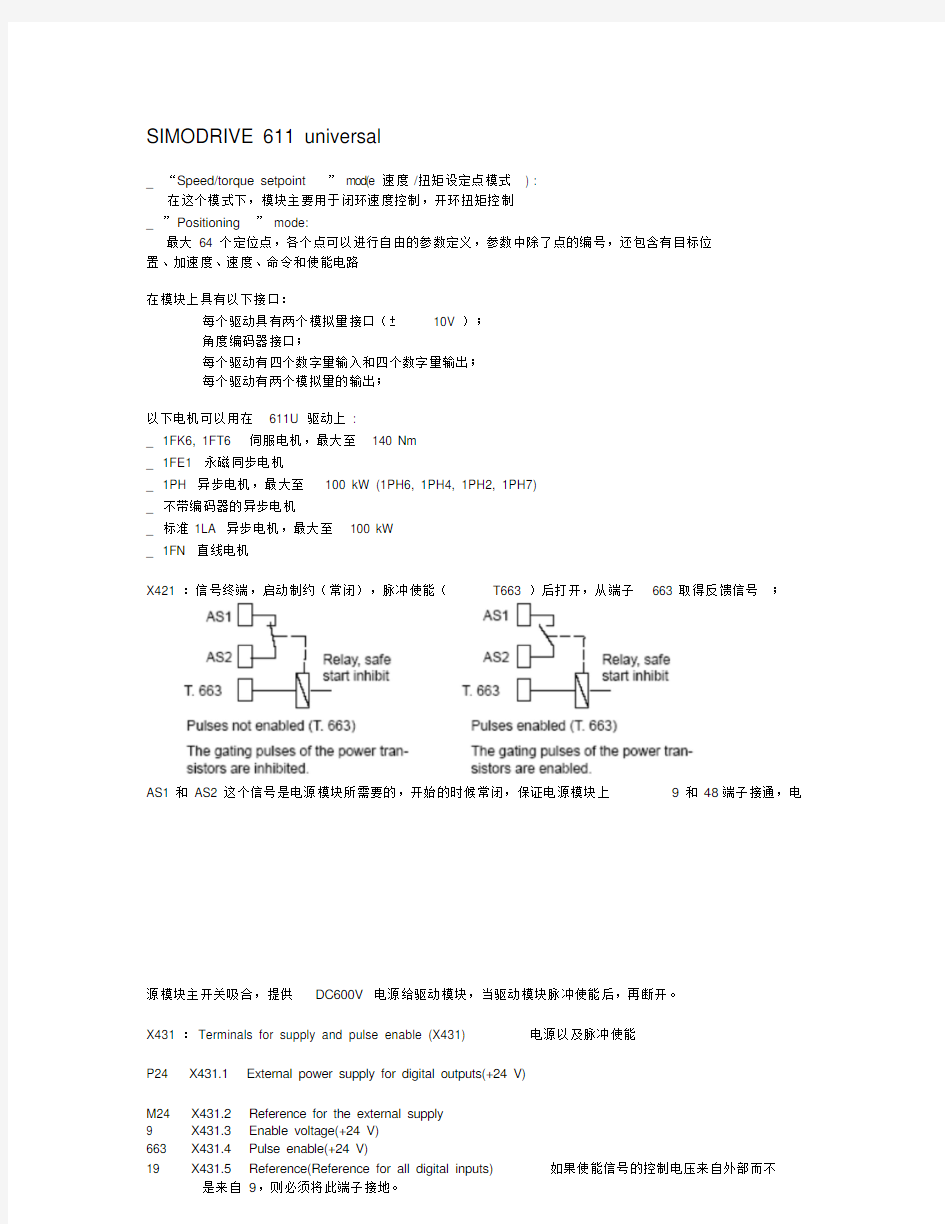
X421 :信号终端,启动制约(常闭),脉冲使能(T663 )后打开,从端子663 取得反馈信号;
AS1 和AS2 这个信号是电源模块所需要的,开始的时候常闭,保证电源模块上9和48端子接通,电
源模块主开关吸合,提供DC600V 电源给驱动模块,当驱动模块脉冲使能后,再断开。
X431 :Terminals for supply and pulse enable (X431) 电源以及脉冲使能
P24 X431.1 External power supply for digital outputs(+24 V)
M24 X431.2 Reference for the external supply
9 X431.3 Enable voltage(+24 V)
663 X431.4 Pulse enable(+24 V)
19 X431.5 Reference(Reference for all digital inputs) 如果使能信号的控制电压来自外部而不
是来自9,则必须将此端子接地。
X471 :Serial interface (X471) 串口(RS232 )
1 RS485 DATA+ 6 Reserved
2 RS232 TxD 7 RS232 CTS
3 RS232 RxD 8 RS232 RTS
4 Reserved 9 RS48
5 DATA –
5 Ground 0 V
利用模块前面S1拨码开关切换为RS485 串口;
connect a PG /PC to “SIMODRIVE 611 universal (RS232 connecting cable with RTS/CTS lines )
connect a PG/PC to “SIMODRIVE 611 universal (RS232 connecting cable without RTS/CTS lines )
Cable diagram for
RS485
RS485 connecting cable:
PG/PC < ––> RS232/RS485 interface converter < ––> SIMODRIVE 611 universal
P0801 = 1 changeover RS232/RS485
X423 :PROFIBUS –DP interface (X423) for the optional PROFIBUS –DP3 module 可选择的DP 口
其9针接线图同X471 接口;
X351 :Equipment bus (X351) 驱动总线(带状电缆,34 针)
Voltages: various
Signals: various
X34 :Test sockets (X34) 测试端子
DAU1 Test socket 12) DAU2 Test
socket 22)
M Reference
Test socket: 2 mm
Resolution: 8 bit
Voltage range: 0 V to 5 V
Maximum current: 3 mA
X411, X412 :Encoder connection (X411, X412) 编码器连接口
X411 ––Motor encoder connection, drive A
X412 ––Motor encoder connection, drive B or connection, direct measuring system(from SW 3.3)
X441 :Analog outputs (X441) 模拟量输出接口
75.A X441.1 Analog output (Can be freely parameterized )
16.A X441.2 Analog output (Can be freely parameterized )
75.B X441.3 Analog output (Can be freely parameterized )
16.B X441.4 Analog output (Can be freely parameterized )
15 X441.5 Reference
X453, X454 :Terminals for the analog inputs and digital inputs/outputs (X453, X454) 模拟量输入以及数字量输入/输出接口
56.A X453.1 56.B X454.1 None
14.A X453.2 14.B X454.2 None
24.A X453.3 24.B X454.3 None
20.A X453.4 20.B X454.4 None
65.A X453.5 65.B X454.5 Controller enable drive –specific
9 X453.6 9 X454.6 Enable voltage(+24 V)
I0.A X453.7 I0.B X454.7 Digital input Fast input 快速输入
I1.A X453.8 I1.B X454.8 Digital input 1 O0.A X453.9 O0.B
X454.9 Digital output 0 O1.A X453.10 O1.B X454.10 Digital output 1
You can parameterize “SIMODRIVE 611 universal ”as follows:
_ using the display and o perator unit on the front panel of “SIMODRIVE
611 universal ”
_ using the parameterizing and start –up tool
(SimoCom U) on a PG/PC
–SimoCom U via serial interface (RS232/RS485)
––> refer to Chapter 3.3.3
–SimoCom U via PROFIBUS –DP (CP 5511/CP 5611/CP 5613)
––> refer to Chapter 3.3.4
这些只有在POWER ON 后才能激活的参数,在模块的显示面板上在文字的前面会加上一个“.”。The parameters, which are effective after POWER ON, are designated in the parameter display
by a point after the drive letters.
举例:
Example:
Changing a
parameter value
Task description:
The analog setpoint is to be inverted via terminal 56.B/14.B. In this
case, in drive B, parameter P0608 must be set to 1.
Assumptions:
_ The drive was already commissioned once.
_ Presently “_ _ _ run ”is being displayed.
Operator actions:
1. Switch in the parameterizing mode 转换到参数设定模式
––> press any key on the operator unit (e.g. “P”)
2. Select drive B 选择驱动 B
––> Simultaneously press the PLUS and MINUS keys
3. Remove write protection 去掉参数的写保护
––> Set P0651 to 4
4. Activate inversion, terminals 56.B/14.B 激活版本
––> Set P0608 to 1
5. Save the parameters in the FEPROM 保存修改的参数
––> Set P0652 to 1
6. Re –activate write protection 增加写保护
––> Set P0651 to 0
Communications via PROFIBUS –DP 利用PROFIBUS 进行通讯
The net data structure for cyclic data transfer is sub –divided into two areas, which are transferred in each telegram.
Parameter area (PKW, parameter identification value) 参数区,读写参数以及读出错误信息
Process data area (PZD, process data)
这个区域包含控制字、设定点、状态信息和实际值
–control words and setpoints (task: master ––> drive) and
–status words and actual values (responses: drive ––> master) Basic functions of the cyclic data transfer
下图中是输入的控制字影响内部使能信号的电路图。
control signals have a significant effect on the most important status signals and how they are formed. 下图中是611U 发出的一些状态信号
Description of the control words (setpoints)
Control word STW1 (n –set mode)
以CLAAS 机械手为例,介绍关于Software,Following error monitoring,Position monitoring,Standstill monitoring 的具体含义以及对,见下图:
315 Minus software limit switch 890.0mm
316 Plus software limit switch 16380.0mm
318:0 Dymanic following error monitoring tolerance 4.00mm
320 Position monitoring time 1000.0ms
321 Positioning window 1.00mm
325 Standstill monitor time 400.0ms
326 Standstill window 2.00mm
除了软限位外,还要设置必要的硬限位,正方向和负方向,当各轴运行到硬限位的时候,直接有信
号送到611U 模块的输入点,随后此轴电机开始以参数P0104 设置的减速度制动,当硬限位被压
上,会出现报警140 或者141 。
软限位的设定通过参数P0314 来进行激活,并且必须设置了参考点,当软限位被激活,出现132 或
者133 报警,对于旋转轴而言,自动默认为不激活软限位
104 Maximum deceleration
314 Activating software limit switch
Fault 132 (drive is located after the minus software limit switch)
Fault 133 (drive is located after the plus software limit switch)
P0310 (cam switching position 1) ––> cam switching signal 1
P0311 (cam switching position 2) ––> cm switching signal 2
Parameter range (PKW area)
PPO :参数过程数据
PKW :参数代码及数值
PZD :过程数据
PKE :参数ID
IND :子参数代码
PWE :参数数值
AK :任务和响应代码
PNU :参数代码
Programming traversing blocks
Traversing blocks 最大有64个,范围从
80:0~86:63 80:0 80:1 ... Block number
A traversing block must be assigned a block number between 0 and 63,
so that it becomes valid and can be started.
... 80:63
81:0 81:1 ... Position
Specifies the target position in the block to be approached.
... 81:63
82:0 82:1 ... Velocity
Specifies the velocity with which the target position is approached.
... 82:63
83:0 83:1 ... Acceleration override
This allows the acceleration to be influenced, referred to P0103.
... 83:63
84:0 84:1 ... Deceleration override
This allows the deceleration to be influenced referred to P0104.
... 84:63
85:0 85:1 ... Command
Each traversing block must contain a command (refer to Table 6-36).
1 POSITIONING (Standard)
+: Block number, position, velocity,
Acceleration override, deceleration override, mode
2/3 ENDLESS TRAVERSING_POS/ENDLESS TRAVERSING_NEG
+: Block number, velocity,
Acceleration override, deceleration override, mode
4 WAITING
+: Block number, delay time in the ”command parameter ”, mode
5 GOTO
+: Block no., target block no. in the “command parameter ”, mode 6 / 7 SET_O/RESET_O
+: Block number, output No. in the “command parameter ”, mode
8 FIXED ENDSTOP (from SW 3.3) +: Block
number, position, velocity, Acceleration
override, deceleration override,
Value range and units for clamping
torque/clamping force in
the “Command parameter ”, mode
9 / 10 COUPLING_CLOSE / COUPLING_OPEN (from SW 3.3)
+: Block number, mode
... 85:63
86:0 86:1 ... Command parameters
Additionally required information to execute the command is specified
here.
... 86:63
87:0 87:1 ... Mode
Spindle positioning
(from SW 5.1)
Block sequence circuit Positioning mode IDs Xx xx
Target position
via
0: traversing
block
1: PROFIBUS
xXxx
0: END (standard)
1: CONTINUE WITH
STOP
2: CONTINUE FLYING
3: CONTINUE EXTERNAL
xXxx
0: ABSOLUTE
(standard)
1: RELATIVE
2: ABS_POS
3: ABS_NEG
xxx X
1:
SKIP_
BLOCK
... 87:63