LCD1602 蓝屏带背光 LCD显示屏 1602A-5v 蓝底白字 显示屏
1602 A instructions
LCD USES manual
Directory
(1)Summarize
(2)shape dimension
(3)module mainly hardware description
(4)the external interface module
(5)command instructions
(6)reading and writing operation sequence
(7) software initialization
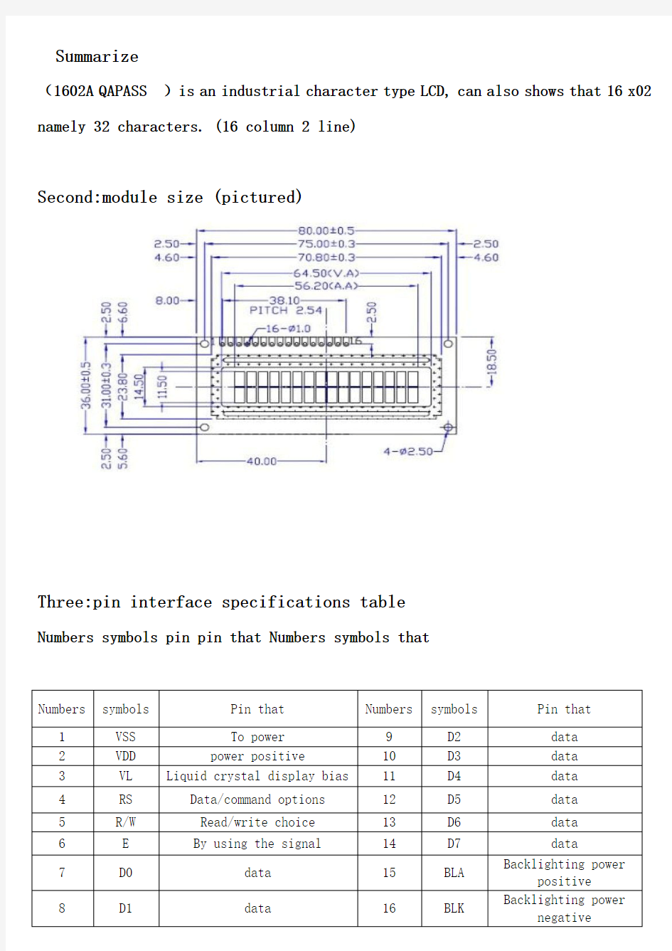
Summarize
(1602A QAPASS )is an industrial character type LCD, can also shows that 16 x02 namely 32 characters. (16 column 2 line)
Second:module size (pictured)
Three:pin interface specifications table
Numbers symbols pin pin that Numbers symbols that
Numbers symbols Pin that Numbers symbols Pin that
1 VSS To power 9 D
2 data
2 VDD power positive 10 D
3 data
3 VL Liquid crystal display bias 11 D
4 data
4 RS Data/command options 12 D
5 data
5 R/W Read/write choice 13 D
6 data
6 E By using the signal 14 D
7 data
7 D0 data 15 BLA Backlighting power
positive
8 D1 data 16 BLK Backlighting power
negative
1 foot: for to power VSS.
2 feet: VDD take 5 V is power.
3 feet: VL for LCD contrast the adjustment, and then when the power is the weakest contrast, grounded contrast the highest, and the contrast
Through high can produce the "ghost", when used, can pass a 10 K adjust potentiometer contrast.
4 feet: RS for registers choice, high electric usually choose data registers, low electric usually choose instruction register.
5 feet: R/W signal lines for reading and writing, high electric usually are read operation, low electricity at ordinary times for write operation. When the RS and the R/W common
For low electricity can be written instructions at ordinary times, or displays address, when RS for low level R/W high power for at ordinary times can read busy signal, and when
RS for high level R/W for low electricity data can be written at ordinary times.
6 feet: E end to make can end, when E is driven by high level jump into low electricity at ordinary times, LCD module executive order.
7 to 14 feet: D0 ~ D7 for eight two-way data cables.
15 feet: back light positive.
16 feet: back light negative.
4. 1602 LCD instructions in time sequence that
1602 LCD module internal controller of article 11 control instruction, as the chart shows:
Numb
ers
instructions RS R/W D7 D6 D5 D4 D3 D2 D1 D0
1 Clear display 0 0 0 0 0 0 0 0 0 1
2 Cursor to return to 0 0 0 0 0 0 0 0 1 *
3 Buy input mode 0 0 0 0 0 0 0 1 I/D S
4 Display the on/off
control
0 0 0 0 0 0 1 D C B
5 The cursor or character
shift
0 0 0 0 0 1 S/C R/L * *
6 Buy function 0 0 0 0 1 DL N F * *
7 Buy character CunZhuQi
address happens
0 0 0 1 Characters CunZhuQi address happens
8 Buy data CunZhuQi 0 0 1 Display the data CunZhuQi address
9 Read busy symbols or
address
0 1 BF Counter address
10 Write count to CFRAM or
DDRAM
1 0 To write data content
11 From CFRAM or DDRAM
readings
1 1 Read data content
14: control command table
1602 LCD module of reading and writing, and the screen and light mark operation operations are through the instructions of programming realize. (note: 1 for high Level, 0 for low level)
Instruction 1: clear display, instruction code 01 H, the cursor is reset to address 00 H position.
Instruction 2: the cursor reset, the cursor to return to address 00 H. Instruction 3: the cursor and display mode I/D: cursor movement direction, high level move to the right, low level moves left S: all on the screen
Is the text moves left or move to the right. High level said effective, low level is invalid.
Instruction 4: display switch control. D: control overall display of open and shut, high level says open display, low level said shut show
And C: the open and close to control a cursor, high level said the cursor, low level said no cursor B: whether to control a cursor flashing,
High level flashing, low level do not twinkle.
Command 5: the cursor or display shift S/C: high electricity at ordinary times of mobile displays text, low electric usually move the cursor.
Command 6: function setting command DL: high electricity at ordinary times for four bus, low electricity at ordinary times for eight bus N: low electricity at ordinary times for single line
Display, high electric usually pair on display F: low electricity at ordinary times display 5 x7 of dot matrix characters, high electric usually display 5 x10 of dot matrix characters.
Command 7: character generator RAM address Settings.
Instructions 8: DDRAM address Settings.
Instructions 9: read the busy signal and the cursor address BF: a sign for busy, high level said busy, this time the module can't receive commands or
The data, if for low level is not busy said.
Directive 10: write data.
11 instructions: read data.
5. The basic operation sequence table
Graph: read operation sequence
Graph: write operation sequence
1602 LCD RAM address mapping and standard word stock list
Liquid crystal display module is a slow display device, so in the execution each instruction before must affirm module mark is busy low electricity
Flat, said were not busy, otherwise this instruction failure. To display character
before display character input address, also is tell module in
Where display character.
6. 1602 internal display address (pictured)
For example the second line the first character address is 40 H, so whether written 40 H can directly to the cursor positioning in the second line
The first character position? So no, because that address to request when the top bits D7 constant for high level 1 so
The actual writing data should be 01000000 B (40 H) + 10000000 B (80 H) = 11000000 B (C0H).
In the LCD module in the initialization of first set its display mode, in LCD module display characters is automatic when the cursor move to the right,
Without human intervention. Every time before you judge input instructions LCD module are in favor of the state.
1602 LCD module of the internal character happen storage
LCD1602汇编显示程序
;1602显示ABC LCD_RS EQU P2.5 LCD_RW EQU P2.6 LCD_EN EQU P2.7 LCD_DATA EQU P3 ;----------------- ORG0000H JMP START ORG0030H ;----------------- LCD: CALL LCD_INIT MOV A, #80H CALL LCD_WCMD MOV A, #'A' CALL LCD_WDATA MOV A, #'B' CALL LCD_WDATA MOV A, #'C' CALL LCD_WDATA AJMP$ ;---------------- DELAY5MS: MOV R6, #10 DL1:DJNZ R7, $ DJNZ R6, DL1 RET ;---------------- LCD_INIT: CALL DELAY5MS MOV A, #38H CALL LCD_WCMD CALL DELAY5MS
CALL DELAY5MS MOV A, #06H CALL LCD_WCMD MOV A, #01H CALL LCD_WCMD MOV A, #0CH CALL LCD_WCMD RET ;===================================== LCD_WCMD: CALL CHECKBUSY CLR LCD_RS JMP W_LCD ;---------------- LCD_WDATA: CALL CHECKBUSY SETB LCD_RS W_LCD: CLR LCD_RW MOV LCD_DATA, A SETB LCD_EN NOP CLR LCD_EN RET ;---------------- CHECKBUSY: PUSH ACC MOV LCD_DATA, #255 CLR LCD_RS SETB LCD_RW BUSYLOOP: SETB LCD_EN NOP MOV A, LCD_DATA CLR LCD_EN JB ACC.7, BUSYLOOP POP ACC RET
lcd1602显示程序
lcd1602显示程序 液晶显示简介①液晶显示原理 液晶显示的原理是利用液晶的物理特性,通过电压对其显示区域进行控制,有电就有显示,这样即可以显示出图形。液晶显示器具有厚度薄、适用于大规模集成电路直接驱动、易于实现全彩色显示的特点,目前已经被广泛应用在便携式电脑、数字摄像机、PDA移动通信工具等众多领域。 ②液晶显示器的分类 液晶显示的分类方法有很多种,通常可按其显示方式分为段式、字符式、点阵式等。除了黑白显示外,液晶显示器还有多灰度有彩色显示等。如果根据驱动方式来分,可以分为静态驱动(StaTIc)、单纯矩阵驱动(Simple Matrix)和主动矩阵驱动(AcTIve Matrix)三种。 ③液晶显示器各种图形的显示原理: 线段的显示 点阵图形式液晶由MN个显示单元组成,假设LCD显示屏有64行,每行有128列,每8列对应1字节的8位,即每行由16字节,共168=128个点组成,屏上6416个显示单元与显示RAM区1024字节相对应,每一字节的内容和显示屏上相应位置的亮暗对应。例如屏的第一行的亮暗由RAM区的000H00FH的16字节的内容决定,当(000H)=FFH时,则屏幕的左上角显示一条短亮线,长度为8个点;当(3FFH)=FFH时,则屏幕的右下角显示一条短亮线;当(000H)=FFH,(001H)=00H,(002H)=00H,(00EH)=00H,(00FH)=00H时,则在屏幕的顶部显示一条由8段亮线和8条暗线组成的虚线。这就是LCD显示的基本原理。 字符的显示 用LCD显示一个字符时比较复杂,因为一个字符由68或88点阵组成,既要找到和显示屏幕上某几个位置对应的显示RAM区的8字节,还要使每字节的不同位为1,其它的为0,为1的点亮,为0的不亮。这样一来就组成某个字符。但由于内带字符发生器的控制器来说,显示字符就比较简单了,可以让控制器工作在文本方式,根据在LCD上开始显
已经采用过-LCD1602显示字符和(RAM)数字的汇编程序
单片机LCD1602显示字符和数字的汇编程序(无聊原创) 1,单片机和LCD1602的连线,和程序结果显示如下图: 2,LCD第一行显示字符XIAORENGUANG第二行显示RAM中40H到46H中的数字。程序如下: ORG 0000H AJMP MAIN RS EQU P2.4 RW EQU P2.5 E EQU P2.6 MAIN: MOV SP,#60H MOV 40H,#01H MOV 41H,#02H MOV 42H,#03H MOV 43H,#04H MOV 44H,#05H MOV 45H,#06H MOV 46H,#07H ACALL DD1 ;DD1是LCD初始化
MOV DPTR,#TABLE1 ACALL DD2;DD2是LCD第一行显示TABLE1 ACALL PPP ;PPP是LCD第二行显示RAM中40H到46H中的数据 SJMP $ DD1: MOV p0,#01H ;清屏 CALL ENABLE MOV p0,#38H ;显示功能 CALL ENABLE MOV p0,#0FH ;显示开关控制 CALL ENABLE MOV p0,#06H ;+1 CALL ENABLE RET DD2: MOV p0,#80H;第一行的开始位置 cALL ENABLE CALL WRITE1;到TABLE1取码? RET DD3: MOV p0,#0C0H;第二行的位置 CALL ENABLE CALL WRITE1;到TABLE2 取码 RET ENABLE: CLR RS ;送命令 CLR RW CLR E CALL DELAY SETB E RET WRITE1: MOV R1,#00H ;显示table中的值 A1: MOV A,R1;到table取码 MOVC A,@A+DPTR call wRITE2 ;显示到lcd INC R1 CJNE A,#00H,A1 ;是否到00h RET WRITE2:MOV p0,A ;显示 SETB RS CLR RW CLR E CALL DELAY SETB E RET
1602液晶显示计算器电路图及程序
#include #include Write_Command(0x0c); Write_Command(0x06); } void LCD_Printfc(uchar hang,uchar lie,uchar sign) { uchar a; if(hang == 1) a = 0x80; if(hang == 2) a = 0xc0; a = a + lie; Write_Command(a); Write_Data(sign); } void LCD_Display(uchar *tab1) { uchar i; Write_Command(0x80); for(i=0; i<16; i++) { Write_Data(tab1[i]); delay(); } /* Write_Command(0xc0); for(i=0; i<16; i++) { Write_Data(tab2[i]); delay(); }*/ } void time_view(void) { if(second == 60) { minite ++; second = 0; } if(minite == 60) { hour++; minite = 0; } if(hour == 24) LCD显示电路 #include /***************************************************** 函数功能:判断液晶模块的忙碌状态 返回值:result。result=1,忙碌;result=0,不忙 ***************************************************/ bit Lcd_BusyTest(void) { bit result; RS=0; //根据规定,RS为低电平,RW为高电平时,可以读状态 RW=1; E=1; //E=1,才允许读写 _nop_(); //空操作 _nop_(); _nop_(); _nop_(); //空操作四个机器周期,给硬件反应时间 result=BF; //将忙碌标志电平赋给result E=0; return result; } /***************************************************** 函数功能:将模式设置指令或显示地址写入液晶模块 入口参数:dictate ***************************************************/ void Lcd_WriteCom (unsigned char dictate) { while(Lcd_BusyTest()==1); //如果忙就等待 RS=0; //根据规定,RS和R/W同时为低电平时,可以写入指令RW=0; E=0; //E置低电平(写指令时就是让E从0到1发生正跳变,所以应先置"0" _nop_(); _nop_(); //空操作两个机器周期,给硬件反应时间 Lcd_Data=dictate; //将数据送入P0口,即写入指令或地址 _nop_(); _nop_(); _nop_(); _nop_(); //空操作四个机器周期,给硬件反应时间 E=1; //E置高电平 _nop_(); _nop_(); _nop_(); _nop_(); //空操作四个机器周期,给硬件反应时间 E=0; //当E由高电平跳变成低电平时,液晶模块开始执行命令} /***************************************************** 函数功能:指定字符显示的实际地址 入口参数:x #include "reg51.h" #include "intrins.h" #define uchar unsigned char #define uint unsigned int uchar code table1 []={" WELCOME "}; //欢迎显示,包括空格在内<=16 uchar code table2 []={"Name: "};//欢迎显示,包括空格在内<=16 //************管脚定义************************ sbit lcd_rs = P3^0; //液晶数据命令选择端 sbit lcd_en = P3^1; //液晶使能 //************参数定义************************ uint tvalue;//温度值 uchar tflag;//温度正负标志 uchar data disdata[5]; //************子函数定义************************ void delay(uchar z); //delay延时子程序 void init_lcd(); //LCD1602初始化函数 void write_com(uchar com); //LCD1602写指令函数 void write_data(uchar date); //LCD1602写数据函数 void lcd1602_display(uchar *q,uchar *p);//LCD1602显示函数 void welcome_1(); //LCD1602显示欢迎函数1 //************主函数************************ void main() { welcome_1(); delay(200); while(1); } //************delay延时子程序************************ void delay(uchar z) 仿真截图: //仿真文件网盘地址: //程序: #include sbit P15 = P1^5; sbit P16 = P1^6; sbit P17 = P1^7; sbit P20 = P2^0; sbit P21 = P2^1; sbit P22 = P2^2; sbit P23 = P2^3; sbit P24 = P2^4; sbit P25 = P2^5; sbit P26 = P2^6; sbit P27 = P2^7; sbit P30 = P3^0; sbit P31 = P3^1; sbit P32 = P3^2; sbit P33 = P3^3; sbit P34 = P3^4; sbit P35 = P3^5; sbit P36 = P3^6; sbit P37 = P3^7; //****** DS18B20 ****** #define DQ P17 /*************精确延时函数*****************/ void delay10us(void) //误差0us { unsigned char a,b; for(b=1;b>0;b--) for(a=2;a>0;a--); } void delay20us(void) //误差0us { unsigned char a,b; for(b=1;b>0;b--) for(a=7;a>0;a--); } void delay30us() //误差0us { unsigned char a,b; for(b=3;b>0;b--) for(a=3;a>0;a--); } //51单片机控制温湿度传感器DHT11LCD1602 YL-9最小系统。 # include //***************延时函数************************************* void delay(uchar ms) //延时模块// { uchar i; while(ms--) for(i=0;i<100;i++); } void delay1()//一个for循环大概需要81us 12MHz8us { uchar i; for(i=0;i<1;i++); } //*************************************************************** //lcd模块// BOOL lcd_bz()//测试lcd'1'.'0' { BOOL result; rs=0; // 读忙信号 rw=1; //液晶显示温度 #include "AT89X52.H" #define Ddata P0 sbit RS=P2^7; //命令数据控制端 sbit RW=P2^6; //读写选择端 sbit LCDE=P2^5; //液晶使能端 sbit DQ=P2^0; //ds18b20与单片机连接口 #define uchar unsigned char #define uint unsigned int unsigned char hour=0,min=0,sec=0; //定义初值 unsigned int count=0; unsigned char line1[16]={" temp: "}; //16个字符 unsigned char line2[16]={" time: 00:00:00"}; //16个字符 unsigned char tab[]={'0','1','2','3','4','5','6','7','8','9'}; //数组 uchar data disdata[5]; uint tvalue; //温度值 uchar tflag; //温度正负标志 void time(); /*************************lcd1602程序**************************/ void delay1ms(unsigned int ms)//延时1毫秒(不够精确的) { unsigned int i,j; for(i=0;i void delay5ms()//延时5毫秒(不够精确的) { unsigned int i; for (i=0;i<1000;i++); } void delay50us() { register int i; for (i=0;i<20;i++); } void delay() {unsigned char m,n; for(m=255;m>0;m--) for(n=255;n>0;n--); } void wr_com(unsigned char comm) //********写控制字符程序E=1 RS=0 RW=0 **********// { LCDE=0; //使能端 RS=0; //********RS寄存器选择输入端,当RS=0;当进行写模块操作,指向指令寄存器。 RW=0; //********当RS=1,无论是读操作还是写操作,都是指向数据寄存器。LCDE=1; Ddata=comm; RS=0; RW=0; LCDE=0; /****************************************************************************** ** * 描述: LCD1602 滚动显示* * 显示方式:* * 1、从左到右逐字显示,闪动二次,清屏。* * 2、再从右到左逐字显示,闪动二次,清屏。* * 3、周期性地重复上述显示方式。* ******************************************************************************* */ #include LCD1602显示全部字库字符、看门狗定时器测试 LCD1602液晶内含有192个字符字库,这个程序是分6屏进行显示,整个显示过程长约7秒,看门狗定时器设置时间为8.38秒,刚好显示完全部字符,修改看门狗就可以看到在显示中途重启,比较直观 LCD_E BIT P3.4 ;LCD片选 LCD_RS BIT P3.5 ;指令、数据位 LCD_RW BIT P3.6 ;读、写位 PORT EQU P0 ;端口定义 WDT_COUNT EQU 0E1H ;看门狗 START: LCALL LCD_INIT LCALL WDT_INIT MOV A,#01H ;清屏 LCALL WR_CMD DISP_LOOP: MOV R0,#06H ;循环计数器 MOV R1,#80H ;LCD地址计数器 MOV R2,#00H ;字符表指针计数器 MOV DPTR,#TAB WR_DAT_LOOP: MOV A,R1 ;地址命令 LCALL WR_CMD INC R1 ;地址加一 MOV A,R2 ;表指针 MOVC A,@A+DPTR LCALL WR_DA T LCALL DELAY100MS INC R2 ;表指针加一 CJNE R1,#90H,BIJIAO ;字符是否到16 MOV R1,#0C0H ;到16,换地址 BIJIAO: CJNE R1,#0D0H,WR_DAT_LOOP ;字符数是否到32 MOV R1,#80H ;地址回归 LCALL DELAY1S MOV A,#1B ;清屏 LCALL WR_CMD DJNZ R0,WR_DA T_LOOP MOV WDT_COUNT,#00110111B LJMP DISP_LOOP LCD_INIT: MOV A,#111000B ;8位总线 LCALL WR_CMD MOV A,#10B ;数据指针清零 在日常生活中,我们对液晶显示器并不陌生。液晶显示模块已作为很多电子产品的通过器件,如在计算器、万用表、电子表及很多家用电子产品中都可以看到,显示的主要是数字、专用符号和图形。在单片机的人机交流界面中,一般的输出方式有以下几种:发光管、LED 数码管、液晶显示器。发光管和LED数码管比较常用,软硬件都比较简单,在前面章节已经介绍过,在此不作介绍,本章重点介绍字符型液晶显示器的应用。 在单片机系统中应用晶液显示器作为输出器件有以下几个优点:显示质量高 由于液晶显示器每一个点在收到信号后就一直保持那种色彩和亮度,恒定发光,而不像阴极射线管显示器(CRT)那样需要不断刷新新亮点。因此,液晶显示器画质高且不会闪烁。 数字式接口 液晶显示器都是数字式的,和单片机系统的接口更加简单可靠,操作更加方便。 体积小、重量轻 液晶显示器通过显示屏上的电极控制液晶分子状态来达到显示的目的,在重量上比相同显示面积的传统显示器要轻得多。 功耗低 相对而言,液晶显示器的功耗主要消耗在其内部的电极和驱动IC上,因而耗电量比其它显示器要少得多。 10.8.1 液晶显示简介 ①液晶显示原理 液晶显示的原理是利用液晶的物理特性,通过电压对其显示区域进行控制,有电就有显示,这样即可以显示出图形。液晶显示器具有厚度薄、适用于大规模集成电路直接驱动、易于实现全彩色显示的特点,目前已经被广泛应用在便携式电脑、数字摄像机、PDA移动通信工具等众多领域。 ②液晶显示器的分类 液晶显示的分类方法有很多种,通常可按其显示方式分为段式、字符式、点阵式等。除了黑白显示外,液晶显示器还有多灰度有彩色显示等。如果根据驱动方式来分,可以分为静态驱动(Static)、单纯矩阵驱动(Simple Matrix)和主动矩阵驱动(Active Matrix)三种。 ③液晶显示器各种图形的显示原理: 线段的显示 MS 基于1602字符型液晶显示器的显示系统 姓名:杨越 班级:电子11-1 学号:110400104 一、实习目的 (1)了解飞思卡尔单片机的基本原理,掌握其基本的工作流程。 (2)了解LCD1602的基本原理及用法。 (3)能够熟练使用CodeWarrior软件编写C语言程序,使用BDM仿真器下载 程序。 (4)能够熟练焊接电路板。 二、实验设备与器件 CodeWarrior软件,BDM仿真器,万用电路板,飞思卡尔单片机,LCD1602液晶显示器, 三、实验内容 内容:利用飞思卡尔单片机制作基于1602字符液晶显示器的显示系统 要求:用四个按键控制,按下第一个按键显示1,按下第二个按键显示2,以此类推。 (1)LCD1602液晶显示器的原理:1602共16个管脚,但是编程用到的主要管脚不过三个,分别为:RS(数据命令选择端),R/W(读写选择端),E(使能信号); 以后编程便主要围绕这三个管脚展开进行初始化,写命令,写数据。 以下具体阐述这三个管脚: RS为寄存器选择,高电平选择数据寄存器,低电平选择指令寄存器。 R/W为读写选择,高电平进行读操作,低电平进行写操作。 E端为使能端,后面和时序联系在一起。 除此外,D0~D7分别为8位双向数据线。 操作时序: 注:关于E=H脉冲——开始时初始化E为0,然后置E为1,再清0. 读取状态字时,注意D7位,D7=1,禁止读写操作;D7=0,允许读写操作; 所以对控制器每次进行读写操作前,必须进行读写检测。(即后面的读忙子程序) 指令集: LCD_1602 初始化指令小结: 0x38 设置16*2显示,5*7点阵,8位数据接口 0x01 清屏 0x0F 开显示,显示光标,光标闪烁 0x08 只开显示 0x0e 开显示,显示光标,光标不闪烁 0x0c 开显示,不显示光标 0x06 地址加1,当写入数据的时候光标右移 0x02 地址计数器AC=0;(此时地址为0x80)光标归原点,但是DDRAM中断内容不变 0x18 光标和显示一起向左移动 (2)飞思卡尔单片机的功能及特点:MC9S12XS128是 16 位单片机,由 16 位中央处理单元(CPU12X)、128KB 程序、Flash(P-lash)、8KB RAM、8KB 数据Flash(D-lash)组成片内存储器。主要功能模块包括:内部存储器,内部 PLL 锁相环模块,2 个异步串口通讯 SCI ,1个串行外设接口 SPI MSCAN 模块,1 个8 通道输入/输出比较定时器模块 TIM ,周期中断定时器模块 PIT ,16 通道 A/D 转换模块 ADC ,1 个 8 通道脉冲宽度调制模块 PWM ,输入/输出数字 I/O 口。 #include while (LCD_Data & 0x80); //检测忙信号 return(LCD_Data); } /************************写数据***********************************/ void LCD_WriteData(uchar WDLCD) { LCD_ReadStatus();//检测忙 LCD_Data = WDLCD LCD_RS = 1; LCD_RW = 0; LCD_E = 1;//若晶振速度太高可以在这后加小的延时 LCD_E = 1;//延时 LCD_E = 0; } /************************写指令********************************/ void LCD_WriteCommand(uchar WCLCD,BuysC) //BuysC为0时忽略忙检测{ if (BuysC) LCD_ReadStatus(); //根据需要检测忙 LCD_Data = WCLCD; LCD_RS = 0; LCD_RW = 0; LCD_E = 1; LCD_E = 1; LCD_E = 0; } /*========================================================= 1602液晶显示的实验例子 ------------------------------------------------- | DB4-----P0.4 | RW-------P2.1 | DB5-----P0.5 | RS-------P2.2 | DB6-----P0.6 | E--------P2.0 | DB7-----P0.7 | --------------------------------------------------- LCD1602的简简单显示 =========================================================*/ #include #include #define LCM_RW P2_1 //定义引脚 #define LCM_RS P2_2 #define LCM_E P2_0 #define LCM_Data P0 #define Busy 0x80 //用于检测LCM状态字中的Busy标识 /*------------------------------------------ 子函数声明 ------------------------------------------*/ void Write_Data_LCM(unsigned char WDLCM); void Write_Command_LCM(unsigned char WCLCM,BuysC); void Read_Status_LCM(void); void LCM_Init(void); #include 实验三LCD1602液晶显示实验 姓名____ 专业____ 学号—成绩__________ 一、实验目的 1.掌握Keil C51软件与proteus软件联合仿真调试的方法; 2.掌握LCD1602液晶模块显示西文的原理及使用方法; 3.掌握用8位数据模式驱动LCM1602液晶的C语言编程方法; 4.掌握用LCM1602液晶模块显示数字的C语言编程方法。 二、实验仪器与设备 1.微机一台C51集成开发环境仿真软件 三、实验内容 1.用Proteus设计一 LCD1602液晶显示接口电路。要求利用P0口接LCD1602 液晶的 数据端,~做LCD1602液晶的控制信号输入端。~口扩展3个功能键K1~K3参考电 路见后面。 2.编写程序,实现字符的静态和动态显示。显示字符为 第一行:“ 1?姓名全拼”,第二行:“ 2.专业全拼+学号” o 3.编写程序,利用功能键实现字符的垂直滚动和水平滚动等效果显示。显示字符 为: “ 1.姓名全拼2.专业全拼+学号 EXP8 DISPLAY” 主程序静态显示“ My in formation ! ” 四、实验原理 液晶显示的原理:采用的LCD显示屏都是由不同部分组成的分层结构,位于最后面的一层是由荧光物质组成的可以发射光线的背光层,背光层发出的光 线在穿过第一层偏振过滤层之后进入包含成千上万水晶液滴的液晶层,液晶层中的水晶液滴都被包含在细小的单元格结构中,一个或多个单元格构成屏 幕上的一个像素。当LCD中的电极产生电场时,液晶分子就会产生扭曲,从而将穿越其中的光线进行有规则的折射,然后经过第二层过滤层的过滤在屏幕上显示出来。 1. LCD1602采用标准的14引脚(无背光)或16引脚(带背光)接口,各 基于LCD1602液晶显示屏的电子万年历设计 基于LCD1602液晶显示屏的电子万年历设计 摘要 现在是一个知识爆炸的新时代,新产品、新技术层出不穷,电子技术的发展更是日新月异。可以毫不夸张的说,电子技术的应用无处不在,电子技术正在不断地改变我们的生活,改变着我们的世界。在这快速发展的年代,时间对人们来说是越来越宝贵,在快节奏的生活时,人们往往忘记了时间,一旦遇到重要的事情而忘记了时间,这将会带来很大的损失。因此我们需要一个定时系统来提醒这些忙碌的人,而数字化的钟表给人们带来了极大的方便。由于单片机具有灵活性强、成本低、功耗低、保密性好等特点,所以电子日历时钟一般都以单片机为核心,外加一些外围设备来实现。 本设计是一种基于液晶显示屏的电子万年历,该系统结合了LCD显示技术,断电时间保护技术和语音录放技术,系统用点阵式液晶显示时间和日期,具有人性化和美观的页面效果,除具备传统的万年历所具有的时间显示和调整功能之外,该系统还兼有语音报时,闰年补偿等功能;以单片机的C51语言进行软件设计,增加了程序的可读性和可移植性,为了便于扩展和更改,软件的设计采用模块化结构,使程序设计的逻辑关系更加简洁明了。实际使用中该设计能准确地显示时间和日期,能准确清晰地完成语音报时功能。 关键词: 单片机,LCD,语音报时,万年历 引言 万年历是采用数字电路实现对.时,分,秒.数字显示的计时装置,广泛用于个人家庭,车站, 码头办公室等公共场所,成为人们日常生活中不可少的必需品,由于数字集成电路的发展和 石英晶体振荡器的广泛应用,使得数字钟的精度,远远超过老式钟表, 钟表的数字化给人们生产生活带来了极大的方便,而且大大地扩展了钟表原先的报时功能。诸如定时自动报警、按时自动打铃、时间程序自动控制、定时广播、自动起闭路灯、定时开关烘箱、通断动力设备、甚至各种定时电气的自动启用等,但是所有这些,都是以钟表数字化为基础的。因此,研究万年历及扩大其应用,有着非常现实的意义。 市场上有许多电子钟的专用芯片如:LM8363、LM8365等,但它们功能单一,电路连接复杂,不便于调试制作!但是考虑到用单片机配合时钟芯片,可制成功能任意的电子钟,而且可以做到硬件简单、成本低廉。所以本系统采用了以广泛使用的单片机AT89C51技术为核心,配合时钟芯片DS1302。软硬件结合,使硬件部分大为简化,提高了系统稳定性,并采 DHT11测温湿度程序lcd1602显示#include { unsigned char i; i--; i--; i--; i--; i--; i--; } /******************************************/ /*************温湿度读取函数***************/ /******************************************/ char read_data() { unsigned char i,num,temp; num=0; for(i=0;i<8;i++) { flag=2; while((!DHT)&&flag++); delay_10us(); delay_10us(); delay_10us(); if(DHT==1)LM1602液晶显示程序
51单片机控制1602LCD显示程序
LCD1602字符测试显示程序与仿真
【51单片机】温度传感器DS18B20程序-LCD1602显示
DHT11温湿度传感器51单片机在LCD1602显示程序
基于51单片机的1602液晶显示温度和时间的C程序
51单片机 1602显示程序 C语言
LCD1602显示全部字库字符
LCD1602原理及显示程序
LCD1602的电路图和程序
LCD1602简单显示程序(单片机)
LCD1602的简单显示程序
lcd1602按键显示程序
LCD1602液晶显示实验实验报告及程序
基于LCD1602液晶显示屏的电子万年历设计两个C程序
DHT11测温湿度程序lcd1602显示