温度变送器 外文翻译 外文文献 英文文献 TT302 温度变送器
TT302 温度变送器
概述
TT302温度变送器接收毫伏(mV)输出的信号,这类传感器包括热电偶或阻性传感器,例如:热电阻(RTD)。它所接受的信号必须在允许的输入范围之内。允许输入电压范围为-50到500,电阻范围为0到2000欧姆。
功能描述-硬件
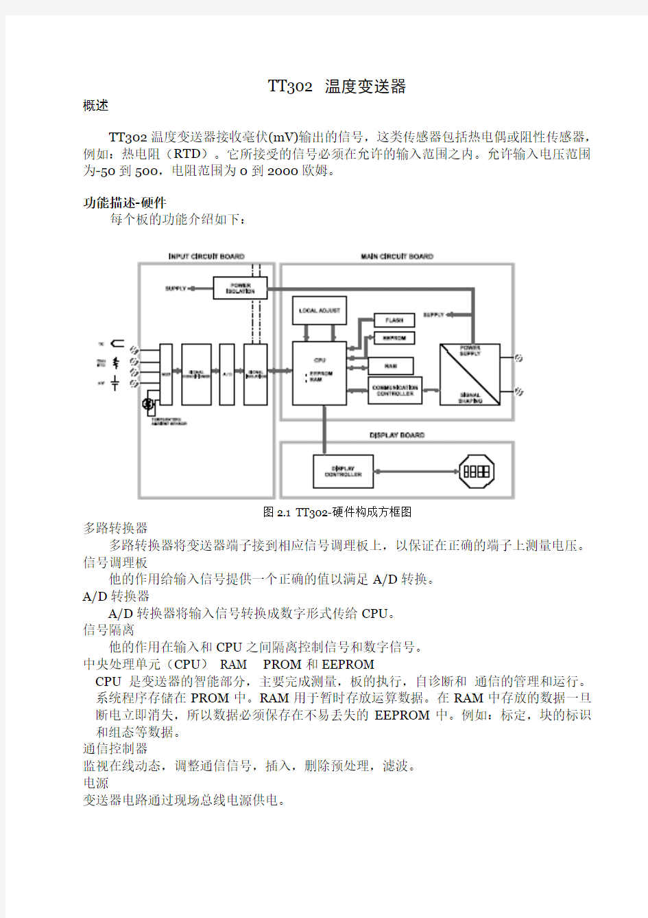
每个板的功能介绍如下:
图2.1 TT302-硬件构成方框图
多路转换器
多路转换器将变送器端子接到相应信号调理板上,以保证在正确的端子上测量电压。信号调理板
他的作用给输入信号提供一个正确的值以满足A/D转换。
A/D转换器
A/D转换器将输入信号转换成数字形式传给CPU。
信号隔离
他的作用在输入和CPU之间隔离控制信号和数字信号。
中央处理单元(CPU)RAM PROM和EEPROM
CPU是变送器的智能部分,主要完成测量,板的执行,自诊断和通信的管理和运行。系统程序存储在PROM中。RAM用于暂时存放运算数据。在RAM中存放的数据一旦断电立即消失,所以数据必须保存在不易丢失的EEPROM中。例如:标定,块的标识和组态等数据。
通信控制器
监视在线动态,调整通信信号,插入,删除预处理,滤波。
电源
变送器电路通过现场总线电源供电。
电源隔离
像信号隔离一样,供给输入部分的信号必须要隔离,电源隔离采用变压器将直流供电电源转换成高频交流供电。
显示控制器
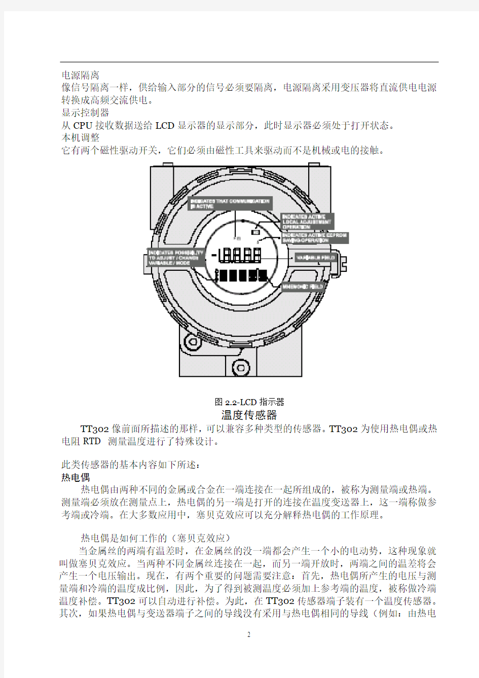
从CPU接收数据送给LCD显示器的显示部分,此时显示器必须处于打开状态。
本机调整
它有两个磁性驱动开关,它们必须由磁性工具来驱动而不是机械或电的接触。
图2.2-LCD指示器
温度传感器
TT302像前面所描述的那样,可以兼容多种类型的传感器。TT302为使用热电偶或热电阻RTD 测量温度进行了特殊设计。
此类传感器的基本内容如下所述:
热电偶
热电偶由两种不同的金属或合金在一端连接在一起所组成的,被称为测量端或热端。测量端必须放在测量点上,热电偶的另一端是打开的连接在温度变送器上,这一端称做参考端或冷端。在大多数应用中,塞贝克效应可以充分解释热电偶的工作原理。
热电偶是如何工作的(塞贝克效应)
当金属丝的两端有温差时,在金属丝的没一端都会产生一个小的电动势,这种现象就叫做塞贝克效应。当两种不同金属丝连接在一起,而另一端开放时,两端之间的温差将会产生一个电压输出。现在,有两个重要的问题需要注意:首先,热电偶所产生的电压与测量端和冷端的温度成比例,因此,为了得到被测温度必须加上参考端的温度,被称做冷端温度补偿。TT302可以自动进行补偿。为此,在TT302传感器端子装有一个温度传感器。其次,如果热电偶与变送器端子之间的导线没有采用与热电偶相同的导线(例如:由热电
偶传感器或接线盒到变送器端子之间采用铜线)那么就会对温度测量产生影响,因此必须要进行冷端补偿。
热电偶的电势在冷端温度为0℃时与热端温度的关系用热电偶分度表来表示。分度表存储在TT302的存储器中,他们是国际标准NBS(B,E,J,K,N,R,S,T)和德国工业标准DIN(L,U) 热电阻(RTD)
热电阻通常被称做RTD,它的工作原理是金属的阻抗会随着温度的升高而增加,存储在TT302的中的热电阻分度表有日本工业标准JIS[1604-81] (Pt50,Pt100)。国际电工委员会IEC,DIN,JIS[1604-89] (Pt50,Pt100&Pt500),通用电气公司GE(Cu10)和DIN(Ni120)。
为使热电阻能够正确测量温度,必须消除传感器到测量电路之间线路电阻所造成的影响。在一些工业应用中,这些导线有几百米长,在环境温度变化剧烈的场所,消除线路电阻的影响是极为重要的。
TT302允许二线制连接,但可能会引起测量误差。此误差取决于接线的长度和导线经过处的温度(图2.3二线制连接)
在二线制连接中,电压U2与热电阻的阻值R TD和导线的电阻R成正比
U2=(R TD+2R X I
图2.3二线制连接
为了避免导线电阻的影响,推荐用三线制连接(图2.4三线制连接)或四线制连接(图2.5三线制连接)
在三线制连接中,端子3是高阻抗输入端,因此,没有电流流过该导线,此导线上也没有压降。电压U2-U1与电阻无关,因为导线电阻上的电压被抵消掉了,它仅与R TD的电阻有关。
U2-U1=(R TD+R)X I-RxI=R TDx I
图2.4 三线制连接
在四线制连接中,端子2和端子3是高阻抗输入端,因此,没有电流流过此端,也没有压降产生。另外两根导线的电阻可不予考虑,这两根导线上也没有测量点,因此电压U2只与R TD电阻值有关
U2=R TDx I
图2.5四线制连接
双通道连接和二线制连接相似,也存在相同的问题(图2.6双通道连接)
导线的电阻需要测量,而且在同一温度下测量也不能忽略他们的阻值,因为长度也会影响使它们不同。
图2.6双通道连接
西门子
SIMATIC PCS 7 PS 展望
投资成本低
标准化的系统基于标准化的部件,因此有高度的挠性和可变性。由于标准化技术的使用使其具有开放性
运行和维护成本低
全自动化
具有电厂设备所需的控制系统的特殊功能和部件
顾客利益
与设备的适应性强
可根据电厂的规模和特性进行扩展和改变
可改变它的性能和记忆功能
由一个服务器来实现从单一控制到分散控制
具备电厂所需的特殊运行,监视,诊断和过程接口
回顾
自1997年投入市场截止到2002年8月100﹪的销售率
在30多个国家投入使用
控制领域:
工业发电厂
生物发电厂
电厂单元机组的辅机
成功的原因
全自动化
功率方案库的使用将SIMATIC PCS 7的兼容性增强
创新性
应用国际公认标准为控制和HMI提供一种开放系统
服务范围
无论何时何地都可得到全球范围内的服务
经验
在工程和节约时间方面提供高质量的规划,管理和方案技术认证
过热器与再热器
过热器是一种将热量传给饱和蒸汽以提高其温度的换热器。蒸汽过热是中心电站所采用的设计特点之一,过热增加了整体循环效率。另外,它降低了汽轮机末级叶片的湿度,因此提高了汽机的内在效率。
一般而言,过热器可分为辐射式过热器、对流式过热器或联合式过热器,这取决于热量是怎样从烟气传给蒸汽的。这些过热器具有不同的运行特性,在机组负荷的宽范围内如能保持出口汽温不变,这样的特性是最希望的。当出口汽温变得过高,则会引起过热器因部分过热而失效。
对流过热器位于炉膛出口,或能够从燃烧的高温产物吸收热能的区域。对流过热器常常通过一束水冷管来遮蔽炉膛辐射热。当这些管子留有足够的间隔时,也能遮断渣粒而减少过热器上的结渣问题。在大型蒸汽发生器系统中,对流过热器常常分为两部分:一级过热器和二级过热器。饱和蒸汽首先进入一级过热器而接受初始过热,一级过热器为于相对低的烟温区,在部分过热后,蒸汽进到二级过热器而完成其过热过程。使过热器分为两级的主要原因是为蒸汽再热器提供一个空间,使烟气向蒸汽有效传热。
辐射过热器没有对流过热器那样得到普遍使用。当需要辐射过热器时,它通常位于炉膛壁上代替一端水冷管。另一种布置是使辐射过热器刚好在屏式管后面,辐射过热器是二级过热器的中间部分。
中心电站锅炉提供蒸汽再热。再热器一般是对流式,且通常位于一级与二级过热器之间的空间。当蒸汽温度在汽机中部分膨胀后,它返回锅炉再热。离开再热器的蒸汽温度通常等于过热蒸汽温度。因为再热器的设计在运行本质上与过热器一样,过热器的讨论将同样适用于再热器。
在过热器的热力设计中,首先确定蒸汽温度。一般而言这点在电站系统设计中完成,以平衡电站初始费用和服役期运行费用。近年来,对于所有蒸汽发生器系统,最佳蒸汽温度约538℃。热力设计中的第二步是近似确定所要求的过热器面积数量。
在过热器表面积被确定后,下一步要考虑的是选择管子的长度、管径和管子数。显然,选择是一个反复的过程,先产生一个尝试解,查看其各种约束是否满足,从各种可接受解中找到最优解。最佳过热器应该有给予设计汽温所必需的足够的传热表面。管子参数(长度和直径)使得蒸汽压降和管子金属温度将不超过设计值。管子金属温度是一个重要参数,对管子材料的选择有很大影响。另外,最佳过热器要使管子布置得使所产生的灰和渣最少。
现代过热器有许多管子通道,管子都顺排布置而不用错排布置。管子通常是圆管,外径为5或6.3cm。没有附在管子上的扩展表面(如肋片),材料的选择取决于蒸汽温度和压力。碳钢的允许温度达430℃,常常用于低温过热器。铬-钼钢、不锈钢或某种类似的耐热合金能承受高达650℃的温度,因而它们被选做高温区过热器。
温度调节与控制对过热器与再热器都很重要,蒸汽温度调节常常要在锅炉指定的时间内进行,原则方法是增加或减少传热面积。蒸汽温度也可以通过调节热烟气温度和质量流量来实现。一般而言,这些都是通过改变过量空气或者蒸发段效果来完成。
在锅炉运行中,有许多因素影响离开过热器和再热器的蒸汽温度,它们包括锅炉负荷、过量空气、给水温度和受热面的清洁度。运行中蒸汽温度的控制必须在不改变设备布置的情况下完成,最有效的措施包括:烟气旁路,燃烧器控制,温度调节,烟气再循环,过量空气以及分隔炉膛。
烟气旁路是控制烟气流过过热器的流量,这种方法是主要缺点是高温区可动闸板操作运行困难,且对负荷变化响应慢。
燃烧器控制通常是控制火焰位置和燃烧速度,使燃烧器倾斜可以使火焰指向或离开过热器,这将改变炉膛的吸热和过热器的烟气温度。随着锅炉负荷减小,燃烧器将逐一推出运行,这将改变燃烧速度,从而改变流经过热器的烟气流量。
温度调节是常使用的方法之一,温度调节器通常位于一级和二级过热器之间。有两种基本形式的温度调节器:一种是管式,一部分过热蒸汽通过换热器管道,将热量传给锅炉水(可以是锅炉给水或锅炉汽包水),随后进入温度调节,从一级过热器分开的蒸汽将会合,一起进入二级过热器;第二种温度调节器是将给水喷入过热蒸汽流中。给水蒸发使蒸汽温度降低,控制给水量就可以控制蒸汽温度。必须注意要使喷水足够纯净,喷水要和过热蒸汽很好地混合,从而使得第二级过热器的入口没有水滴。
烟气再循环通常采用改变炉膛和过热器的吸收率来控制蒸汽温度,当需要蒸汽温度声高时,从省煤器出口取出的一部分烟气将循环返回炉膛底部。因此,炉膛温度降低,导致炉膛吸热减少,而炉膛出口烟温升高。这么高的烟温,加上烟气流量增加,将增加过热器的传热速率,使蒸汽出口温度升高。
温度控制也受所使用的过量空气量的影响,过量空气越多,蒸汽出口温度将越高,其原因与烟气再循环方法的原因类似。必须指出,太多的过量空气将导致锅炉燃烧效率降低。分隔炉膛锅炉是将饱和蒸汽的生产安排在一段,而将过热蒸汽的生产安排在另一段。过热汽温是通过控制两个炉膛中的燃烧速率来调节的,这一方法不经济,很少应用中心电站锅炉。
译文:
TT302—Field bus Temperature Transmitter Operation
The TT302 accepts signals from mV generators such as thermocouples or resistive sensors such as
RTDs. The criterion is that the signal is within the range of the input. For mV, the range is -50 to 500mV and for resistance, 0-2000 Ohm.
Functional Description – Hardware
The function of each block is described below.
Figure 2.1—TT302Block Diagram
MUX Multiplexer
The MUX multiplexes the sensor terminals to the signal conditioning section ensuring that the voltages are measured between the correct terminals.
Signal Conditioner
Its function is to apply the correct gain to the input signals to make them suit the A/D -converter.
A/D Converter
The A/D converts the input signal to a digital format for the CPU.
Signal Isolation
Its function is to isolate the control and data signal between the input and the CPU. (CPU) Central Processing Unit, RAM, PROM and EEPROM
The CPU is the intelligent portion of the transmitter, being responsible for the management and operation of measurement, block execution, self-diagnostics and communication. The program is stored in a PROM. For temporary storage of data there is a RAM. The data in the RAM is lost if the power is switched off. However there is a nonvolatile EEPROM where data that must be retained is stored. Examples, of such data
are trim, calibration, block configuration and identification data.
TT302 - Fieldbus Temperature Transmitter
Communication Controller
It monitors line activity, modulates and demodulates communication signals and inserts and deletes start and end delimiters.
Power Supply
Takes power of the loop-line to power the transmitter circuitry.
Power Isolation
Just like the signals to and from the input section, the power to the input section must be isolated. Isolation is achieved by converting the DC supply into a high frequency AC supply and galvanically separating it using a transformer.
Display Controller
Receives data from the CPU informing which segments of the Liquid Crystal Display, should be turned on.
Local Adjustment
There are two switches that are magnetically activated. They can be activated by the magnetic tool without mechanical or electrical contact.
Figure 2.2 - LCD Indicator
Temperature Sensors
The TT302, as previously explained, accepts several types of sensors. The TT302 is specially designed for temperature measurement using thermocouples or Resistive Temperature Detectors (RTDs).
Some basic concepts about these sensors are presented below.
Thermocouples
Thermocouples are constructed with two wires made from different metals or alloys joined at one end, called measuring junction or "hot junction". The measuring junction should be placed at the point of measurement. The other end of the thermocouple is open and connected to the temperature
transmitter. This point is called reference junction or cold junction.
For most applications, the Seebeck effect is sufficient to explain thermocouple behavior as following:
How the Thermocouple Works (Seebeck Effect)
When there is a temperature difference along a metal wire, a small electric potential, unique to every alloy, will occur. This phenomenon is called Seebeck effect. When two wires of dissimilar metals are joined at one end, and left open at the other, a temperature difference between the two ends will result in a voltage since the potentials generated by the dissimilar materials are different and do not cancel each other out. Now, two important things must be noted. First: the voltage generated by the thermocouple is proportional to the difference between the measuring-junction and the cold junction temperatures. Therefore the temperature at the reference junction must be added to the temperature derived from the thermocouple output, in order to find the temperature measured. This is called cold junction compensation, and is done automatically by the TT302, which has a temperature sensor at the sensor terminals for this purpose. Secondly, if the thermocouple wires are not used, all the way to the terminals of the transmitter (e.g., copper wire is used from sensor-head or marshaling box) will form new junctions with additional Seebeck effects. It will be created and ruin the measurement in most cases, since the cold-junction compensation will be done at the wrong point.
NOTE
The relation between the measuring junction temperature and the generated mili-voltage is tabulated in thermocouple calibration tables for standardized thermocouple types, the reference temperature being 0 oC.
Standardized thermocouples that are commercially used, whose tables are stored in the memory of the TT302, are the following:
. NBS (B, E, J, K, N, R, S & T)
. DIN (L & U)
Resistive Temperature Detectors (RTDs)
Resistance Temperature Detectors, most commonly known as RTD’s, are based on the principle that the resistance of metal increases as its temperature increases. Standardized RTDs, whose tables are stored in the memory of the TT302, are the following:
. JIS [1604-81] (Pt50 & Pt100)
. IEC, DIN, JIS [1604-89] (Pt50, Pt100 & Pt500)
.. GE (Cu10)
.. DIN (Ni120)
For correct measurement of RTD temperature, it is necessary to eliminate the effect of the resistance of the wires connecting the sensor to the measuring circuit. In some industrial applications, these wires may be hundreds of meters long. This is particularly
important at locations where the ambient temperature changes constantly.
The TT302 permits a 2-wire connection that may cause measuring errors, depending on the length of connection wires and on the temperature to which they are exposed. (See Figure 2.3 -Two-Wire Connection).
In a 2-wire connection, the voltage V2 is proportional to the RTD resistance plus the resistance of the wires.
V2 = [RTD + 2 x R] x I
Figure 2.3 - Two-Wire Connection
In order to avoid the resistance effect of the connection wires, it is recommended to use a 3-wire connection (See Figure 2.4 – Three-Wire Connection) or a 4-wire connection (See Figure 2.5 - Four - Wire Connection).
In a 3-wire connection, terminal 3 is a high impedance input. Thus, no current flows through that wire and no voltage drop is caused. The voltage V2-V1 is independent of the wire resistances since they will be cancelled, and is directly proportional to the RTD resistance alone.
V2-V1 =[RTD + R] x I - R x I = R TD x I
Figure 2.4 - Three – Wire Connection
In a 4-wire connection, terminals 2 and 3 are high impedance inputs. Thus, no current flows through those wires and no voltage drop is caused. The resistance of the other two wires is not of interest, since there is no measurement registered on them. Hence the
voltage V2 is directly proportional to the RTD resistance.
(V2 = RTD x I)
Figure 2.5 - Four - Wire Connection
A differential or dual channel connection is similar to the two-wire connection and gives the same problem (See Figure 2.6 - Differential or Dual Connection). The resistance of the wires will be measured and do not cancel each other out in a temperature measurement, since linearization will affect them differently.
Figure 2.6 - Differential or Dual Connection
SIEMENS
Highlight of SIMATIC PCS 7 PS
Low investment costs
.Modular system based on standard components, therefore high degree of flexibility and scalability.
.Open thanks to the use of standard technologies.
Low operation and maintenance costs
.Horizontal integration with Totally Integrated Automation.
.Control system specific functionality and components for power plant requirements. Customer Profits
.Optimum adaptation to the requirements.
.Expansion and adaptations according to size and plant characteristic.
.Scalable performances and memories for control.
.Scalable from single station to distributed control system with client-server architecture.
.Power-plant-specific operation and monitoring,diagnostics and process interface. Facts& Figures of Simatic PCS7 PS
The Scope
.On the market since 1997.
.100 sold to date (as of 08/2002).
.In use in more than 30 countries.
.In control of:
Industrial power plants
Biomass power plants
Auxiliaries of power plants
Reasons behind this success
.Totally Integrated Automation:
Consistent use of SIMATIC PCS7 with Power Solution Library
.Innovation Nature:
We provide an open system using international recognized standards for control and
HMI
.Competence:
Worldwide services which are available for you anytime, anywhere!
.Experience:
Project management and process know-how guarantee for high quality in project
engineering and saving time.
Superheater and Reheater
The superheater is a heat exchanger in which heat is transferred to the saturated
steam to increase its temperature. Stream superheating is one of the design features
accepted in central electric power stations. Superheating raise overall cycle efficiency. In addition, it reduces a moisture level in the last stages of the steam turbine and thus
increases the turbine internal efficiency.
Superheaters are commonly classified as either radiant superheaters, convective superheaters, or combined superheaters, depending on how heat id transferred from the gases to steam. These superheaters have different performance characteristics. The
feature that the outlet steam temperature can stay essentially constant over a wide range of unit load is the most desirable. When the outlet steam temperature becomes excessive, it may cause failures from overheating parts of the superheater.
The convective superheater is located in the furnace exit or in the zone where it can receive thermal energy from the high temperature produces of combustion. The convective superheater is frequently screened from the furnace radiation by a bank of water-filled tubes. These tubes, when adequately spaced, can also intercept the slag particle and reduce slagging problems in superheatrs. Convective superheaters in large steam generator systems are frequently split into two parts: the primary superheater and the secondary superheaater. Saturated steam first enters the primary superheater and receives the initial heating. The primary superheater is located in a zone of relatively low gas temperature. After the partial heating steam moves to the secondary superheater and completes its superheaing process. The main reasons for splitting the superheater are to provide space for the steam reheater and to achieve an effective heat transfer from the gases the steam.
The radiant superheater is not as commonly used as the convective superheater. When the radiant superheater is needed, it is usually placed on the furnace wall replacing a section of water-filled tubes. Another arrangement is to have the radiant superheater just behind the screen tubes. The radiant superheater is an integral part of the secondary superheater.
Central station boilers provide for steam reheating. The reheater is essentially a convective type and usually located in the space between thee primary and secondary superheaters. After steam partially expands in the tubine, it returns to the boiler for reheating. The temperature of steam leaving the reheater is usually equal to the superheated steam temperature. Since the design and operation of reheater are essentially the same as superheaters, the discussion of superheaters will be equally applicable to reheaters.
In superheater thermal design, the steam temperature is first determined. This is generally accomplished in the plant system design, balancing the plant initial cost against the lifttime operating cost. In recent years the optimum steam temperature is approximately 538℃for all large steam generation systems. In the second step, the amount of superheater surface required is approximated.
After the amount of superheater surface id determined, the next consideration is to select the tube length, tube diameter, and the number of tubes. Evidently, the selection is an iterative process, generating a trial solution and checking to see whether all constraints are met. From several acceptable solutions, the optimum is found. The optimum superheater should have enough heat transfer surface necessary to give the design steam temperature. The tube parameters(length and diameter) are such that the steam pressure drop and tube metal temperature will not exceed the design values. The tube metal temperature is an important parameter and has a strong influence on the tube material selection. In addition, the optimum superheater should have its tubes so spaced that minimum ash and slag deposits will result.
Modern superheaters have many tube passes, and the tubes are arranged in-line rather than staggered. The tubes are usually cylindrical and have 5 or 6.3cm outside diameter. There is no extended surface(i.e.fins)attached to the tubes. The material selection depends on the steam temperature and pressure. Carbon steel has an allowable temperature up to 430℃and is frequently used for loe-temperature superheaters. Chrome-moly, stainless steel, or same similar heat resistant alloy can withstand the temperature up to 650℃. Therefore they are selected for the
Superheater in a high-temperature zone.
Temperature regulation and control are importation for both superheaters and reheaters. Steam temperature adjustments are frequently made at the time of the commissioning of a boiler. The principal methods are an addition or regulating
the hot gas temperature and mass flow rate. These are generally accomplished by changing the excess air or the effectiveness of the evaporation section.
During a boiler operation, there are many factors affecting the temperature of steam leaving the superheater and reheater. These include a boiler load, excess
air, feedwater temperature, and cleanliness of heating surfaces. Control of steam temperature during operation must be done without changing the arrangement of equipment. The most effective approaches are gas bypass, burner control, attemperation, gas recirculation, excess air, divided furnace.
A gas bypass is to control the gas flow rate to superheater. The main disadvantages of this approach are the operating difficulties experienced by the movable dampers located in the high-temperature zone and the slow response to load change.
Burner control is used to control the flame location and combustion rate. Tilting burners can direct the flame toward or away from the superheater. These will result in a change of heat absorption in the furnace and change of gas temperature in the superheater. As the boiler load is reduced, burners are removed one by one from service. This will change the combustion rate and, thus, change the gas flow rate to the superheater.
Attemperation is one of approaches frequently used. The attemperator is usually located at the point between the primary and secondary superheaters.
There are two basic types of attemperator. The first is the tubular type in which some of superheated steam is passed through the tubes of a heat exchanger and has heat transferred to the boiler water(either boiler feedwater or water in the boiler drum).Subsequent to attemperation, the divided streams from the primary superheater will combine and enter the secondary superheater.
The second type of attemperator involves a spray of feedwater into the atream ofsuperheated steam. The feedwater evaporates and reduces the steam temperature. Controlling the amount of feedwater will result in control of the ateam temperature. Care must be exercised to ensure that the spray water has sufficient purity. The spray water should mix well with the superheated steam so that there are no water droplets in the inlet of the secondary superjeater.
Gas recirculation is used to control the steam temperature by changing the heat absorption rates both in the furnace and in the superheater. When the ateam temperature needs to be raised, some of the furnace. Therefore, the furnace temperature will become lower, resulting in a lower heat absorption in the furnace and thereby a higher flue gas temperature in the furnace exit. This high gas temperature, combined with an increase in the gas floe rate, will increase the heat transfer rate in the superheater and thus increase the steam outlet temperature.
Temperature control can be affected bu using different amounts of excess air. the more the excess air, the higher the steam outlet temperature would be. The reasons for this are similar to those for the gas recirculation method. It must be pointed out, however, that too much excess air will result in a reduction of boiler combustion efficiency. A divided-furnace boiler is usually arranged with a generation of saturated steam in one section and a superheating of steam in another section. The temperature of the superheated steam is regulated by controlling the firing rates in the two furnaces. This method is not economical and is seldom applied in a central electric power station.
红外数据通信技术外文翻译文献
红外数据通信技术外文翻译文献(文档含中英文对照即英文原文和中文翻译) Infrared Remote Control System Abstract Red outside data correspondence the technique be currently within the scope of world drive extensive usage of a kind of wireless conjunction technique, drive numerous hardware and software platform support. Red outside the transceiver product have cost low, small scaled turn, the baud rate be quick, point to point SSL, be free from electromagnetism thousand Raos
etc. characteristics, can realization information at dissimilarity of the product fast, convenience, safely exchange and transmission, at short distance wireless deliver aspect to own very obvious of advantage. Along with red outside the data deliver a technique more and more mature, the cost descend, red outside the transceiver necessarily will get at the short distance communication realm more extensive of application. The purpose that design this system is transmit customer’s operation information with infrared rays for transmit media, then demodulate original signal with receive circuit. It use coding chip to modulate signal and use decoding chip to demodulate signal. The coding chip is PT2262 and decoding chip is PT2272. Both chips are made in Taiwan. Main work principle is that we provide to input the information for the PT2262 with coding keyboard. The input information was coded by PT2262 and loading to high frequent load wave whose frequent is 38 kHz, then modulate infrared transmit dioxide and radiate space outside when it attian enough power. The receive circuit receive the signal and demodulate original information. The original signal was decoded by PT2272, so as to drive some circuit to accomplish customer’s operation demand. Keywords: Infrared dray;Code;Decoding;LM386;Red outside transceiver 1 Introduction 1.1 research the background and significance Infrared Data Communication Technology is the world wide use of a wireless connection technology, by the many hardware and software platforms supported. Is a data through electrical pulses and infrared optical pulse switch between the wireless data transceiver technology.
英文文献翻译
中等分辨率制备分离的 快速色谱技术 W. Clark Still,* Michael K a h n , and Abhijit Mitra Departm(7nt o/ Chemistry, Columbia Uniuersity,1Veu York, Neu; York 10027 ReceiLied January 26, 1978 我们希望找到一种简单的吸附色谱技术用于有机化合物的常规净化。这种技术是适于传统的有机物大规模制备分离,该技术需使用长柱色谱法。尽管这种技术得到的效果非常好,但是其需要消耗大量的时间,并且由于频带拖尾经常出现低复原率。当分离的样本剂量大于1或者2g时,这些问题显得更加突出。近年来,几种制备系统已经进行了改进,能将分离时间减少到1-3h,并允许各成分的分辨率ΔR f≥(使用薄层色谱分析进行分析)。在这些方法中,在我们的实验室中,媒介压力色谱法1和短柱色谱法2是最成功的。最近,我们发现一种可以将分离速度大幅度提升的技术,可用于反应产物的常规提纯,我们将这种技术称为急骤色谱法。虽然这种技术的分辨率只是中等(ΔR f≥),而且构建这个系统花费非常低,并且能在10-15min内分离重量在的样本。4 急骤色谱法是以空气压力驱动的混合介质压力以及短柱色谱法为基础,专门针对快速分离,介质压力以及短柱色谱已经进行了优化。优化实验是在一组标准条件5下进行的,优化实验使用苯甲醇作为样本,放在一个20mm*5in.的硅胶柱60内,使用Tracor 970紫外检测器监测圆柱的输出。分辨率通过持续时间(r)和峰宽(w,w/2)的比率进行测定的(Figure 1),结果如图2-4所示,图2-4分别放映分辨率随着硅胶颗粒大小、洗脱液流速和样本大小的变化。
外文翻译 - 英文
The smart grid Smart grid is the grid intelligent (electric power), also known as the "grid" 2.0, it is based on the integration, high-speed bidirectional communication network, on the basis of through the use of advanced sensor and measuring technology, advanced equipme nt technology, the advanced control method, and the application of advanced technology of decision support system, realize the power grid reliability, security, economic, efficient, environmental friendly and use the security target, its main features include self-healing, incentives and include user, against attacks, provide meet user requirements of power quality in the 21st century, allow all sorts of different power generation in the form of access, start the electric power market and asset optimizatio n run efficiently. The U.S. department of energy (doe) "the Grid of 2030" : a fully automated power transmission network, able to monitor and control each user and power Grid nodes, guarantee from power plants to end users among all the nodes in the whole process of transmission and distribution of information and energy bi-directional flow. China iot alliance between colleges: smart grid is made up of many parts, can be divided into:intelligent substation, intelligent power distribution network, intelli gent watt-hourmeter,intelligent interactive terminals, intelligent scheduling, smart appliances, intelligent building electricity, smart city power grid, smart power generation system, the new type of energy storage system.Now a part of it to do a simple i ntroduction. European technology BBS: an integration of all users connected to the power grid all the behavior of the power transmission network, to provide sustained and effective economic and security of power. Chinese academy of sciences, institute of electrical: smart grid is including all kinds of power generation equipment, power transmission and distribution network, power equipment and storage equipment, on the basis of the physical power grid will be modern advanced sensor measurement technology, network technology, communication
人工智能专业外文翻译-机器人
译文资料: 机器人 首先我介绍一下机器人产生的背景,机器人技术的发展,它应该说是一个科学技术发展共同的一个综合性的结果,同时,为社会经济发展产生了一个重大影响的一门科学技术,它的发展归功于在第二次世界大战中各国加强了经济的投入,就加强了本国的经济的发展。另一方面它也是生产力发展的需求的必然结果,也是人类自身发展的必然结果,那么随着人类的发展,人们在不断探讨自然过程中,在认识和改造自然过程中,需要能够解放人的一种奴隶。那么这种奴隶就是代替人们去能够从事复杂和繁重的体力劳动,实现人们对不可达世界的认识和改造,这也是人们在科技发展过程中的一个客观需要。 机器人有三个发展阶段,那么也就是说,我们习惯于把机器人分成三类,一种是第一代机器人,那么也叫示教再现型机器人,它是通过一个计算机,来控制一个多自由度的一个机械,通过示教存储程序和信息,工作时把信息读取出来,然后发出指令,这样的话机器人可以重复的根据人当时示教的结果,再现出这种动作,比方说汽车的点焊机器人,它只要把这个点焊的过程示教完以后,它总是重复这样一种工作,它对于外界的环境没有感知,这个力操作力的大小,这个工件存在不存在,焊的好与坏,它并不知道,那么实际上这种从第一代机器人,也就存在它这种缺陷,因此,在20世纪70年代后期,人们开始研究第二代机器人,叫带感觉的机器人,这种带感觉的机器人是类似人在某种功能的感觉,比如说力觉、触觉、滑觉、视觉、听觉和人进行相类比,有了各种各样的感觉,比方说在机器人抓一个物体的时候,它实际上力的大小能感觉出来,它能够通过视觉,能够去感受和识别它的形状、大小、颜色。抓一个鸡蛋,它能通过一个触觉,知道它的力的大小和滑动的情况。第三代机器人,也是我们机器人学中一个理想的所追求的最高级的阶段,叫智能机器人,那么只要告诉它做什么,不用告诉它怎么去做,它就能完成运动,感知思维和人机通讯的这种功能和机能,那么这个目前的发展还是相对的只是在局部有这种智能的概念和含义,但真正完整意义的这种智能机器人实际上并没有存在,而只是随着我们不断的科学技术的发展,智能的概念越来越丰富,它内涵越来越宽。 下面我简单介绍一下我国机器人发展的基本概况。由于我们国家存在很多其
指纹识别系统(文献综述)
指纹识别方法的综述 摘 要: 对在指纹的预处理和特征提取、指纹分类、指纹的匹配过程中的方向图、滤波器、神经网络等关 键性原理和技术做了详细的说明,并对在各个过程中用到的方法做了进一步的比较,讨论了各种方法的优越性。 0 引 言 自动指纹识别是上世纪六十年代兴起的,利用计算机取代人工来进行指纹识别的一种方法。近年 来,随着计算机技术的飞速发展,低价位指纹采集仪的出现以及高可靠算法的实现,更使得自动指纹识 别技术越来越多地进入到人们的生活和工作中,自动指纹识别系统的研究和开发正在成为国内外学术 界和商业界的热点。相对于其他生物特征鉴别技术例如语音识别及虹膜识别,指纹识别具有许多独到 的优点,更重要的是它具有很高的实用性和可行性,已经被认为是一种理想的身份认证技术,有着十分 广泛的应用前景,是将来生物特征识别技术的主流。 1 指纹取像 图 1 是一个自动指纹识别系统AFIS(Automated Fingerprint Identification System) 的简单流程。 → → → ↓ ↑ ———— 将一个人的指纹采集下来输入计算机进行处理是指纹自动识别的首要步骤。指纹图像的获取主要利用设备取像,方便实用,比较适合AFIS 。利用设备取像的主要方法又利用光学设备、晶体传感器和超声波来进行。光学取像设备是根据光的全反射原理来设计的。晶体传感器取像是根据谷线和脊线皮肤与传感器之间距离不同而产生的电容不同来设计的。超声波设备取像也是采用光波来取像,但由于超声波波长较短,抗干扰能力较强,所以成像的质量非常好。 2 图像的预处理与特征提取 无论采取哪种方法提取指纹,总会给指纹图像带来各种噪声。预处理的目的就是去除图像中的噪 音,把它变成一幅清晰的点线图,以便于提取正确的指纹特征。预处理是指纹自动识别过程的第一步, 它的好坏直接影响着指纹识别的效果。常用的预处理与特征提取( Image Preprocessing and Feature Ex 2 t raction) 方法的主要步骤包括方向图计算、图像滤波、二值化、细化、提取特征和后处理。当然这些步骤 可以根据系统和应用的具体情况再进行适当变化。文献[ 1 ]提出了基于脊线跟踪的方法能够指纹取像 图像预处理 特征提取 指纹识别 数据库管理
旅游管理专业论文外文文献翻译
外文资料译文及原文 译文(一) 消费者体验旅游和品牌的结合 米契尔罗伯特 定义消费者体验旅游 制造工厂参观,公司博物馆和公司访客中心表现为被不同名字已知的观光事业片段:制造业观光事业,工业的吸引、工业的观光事业和工业的遗产观光事业。在每一个描述性的长期的共同目标是在消费者学习品牌,其运作,生产过程,历史和历史意义的时候建立一个消费者和品牌之间的纽带。有人建议在这里CET代表一个统一的主题的旅游。这个术语捕捉消费者的消费能力发现更多关于他们所消费的品牌,而制造商可以在与该工厂的客人接触的30-120分钟时间里建立与这些消费者更密切的关系。 参与的品牌 品牌经理寻求解决在三个层次消费者的需求: (1)功能(对消费者提供解决问题的办法); (2)符号(提供心理欲望满意度); (3)经历(提供感官快乐,品种,认知,刺激) CET可以通过视觉地介绍品牌,运作,生产工艺,历史和历史意义加强消费者和品牌之间的纽带。这种纽带可以被看作是个人品牌参与和品牌忠诚度的提高。认知参与反映了消费者对产品的兴趣(或学习更多)。CET可以通过刺激消费者对于品牌和生产过程的想象提高消费者的认知水平。此外,积极口碑沟通刺激满足旅客可能会比其他形式的促销更可信。 缺乏现有的直接研究关注 迄今为止,CET已经在行销文学中受到一点注意。米契尔和米契尔(2001年)对此内容这种的旅游网站进行了评估。此外,这些相同的作者已经评估食物和饮料工业中的现象(米契尔和米契尔,2000年),非营利部门(米契尔和米契尔,2001年b),和整体经济(米契尔等, 2001)。米契尔和米契尔(2002)为学者提出了格式,用来评估在当地的服务领域这些设施的地方利益。该主题通常包括对整合营销的简要讨论,但已收到直接研究的关注很有限。
通信工程项目毕业材料外文翻译
用于多跳认知无线电网络的分布式网络编码控制信道 Alfred Asterjadhi等著 1 前言 大多数电磁频谱由政府机构长期指定给公司或机构专门用于区域或国家地区。由于这种资源的静态分配,许可频谱的许多部分在许多时间和/或位置未使用或未被充分利用。另一方面,几种最近的无线技术在诸如IEEE802.11,蓝牙,Zigbee之类的非许可频段中运行,并且在一定程度上对WiMAX进行操作;这些技术已经看到这样的成功和扩散,他们正在访问的频谱- 主要是2.4 GHz ISM频段- 已经过度拥挤。为了为这些现有技术提供更多的频谱资源,并且允许替代和创新技术的潜在开发,最近已经提出允许被许可的设备(称为次要用户)访问那些许可的频谱资源,主要用户未被使用或零星地使用。这种方法通常被称为动态频谱接入(DSA),无线电设备发现和机会性利用未使用或未充分利用的频谱带的能力通常称为认知无线电(CR)技术。 DSA和CR最近都引起了无线通信和网络界的极大关注。通常设想两种主要应用。第一个是认知无线接入(CW A),根据该认知接入点,认知接入点负责识别未使用的许可频谱,并使用它来提供对次用户的接入。第二个应用是我们在这个技术中研究的应用,它是认知自组织网络(CAN),也就是使用 用于二级用户本身之间通信的无许可频谱,用于诸如点对点内容分发,环境监控,安全性等目的,灾难恢复情景通信,军事通信等等。 设计CAN系统比CW A有更多困难,主要有两个原因。第一是识别未使用的频谱。在CW A中,接入点的作用是连接到互联网,因此可以使用简单的策略来推断频谱可用性,例如查询频谱调节器在其地理位置的频谱可用性或直接与主用户协商频谱可用性或一些中间频谱经纪人另一方面,在CAN中,与频谱调节器或主要用户的缺乏直接通信需要二级用户能够使用检测技术自己识别未使用的频谱。第二个困难是辅助用户协调媒体访问目的。在CW A中存在接入点和通常所有二级用户直接与之通信(即,网络是单跳)的事实使得直接使用集中式媒体接入控制(MAC)解决方案,如时分多址(TDMA)或正交频分多址(OFDMA)。相反,预计CAN将跨越多跳,缺少集中控制器;而对于传统的单通道多跳自组织网络而言,这个问题的几个解决方案是已知的,因为假设我们处理允许设备访问的具有成
计算机网络-外文文献-外文翻译-英文文献-新技术的计算机网络
New technique of the computer network Abstract The 21 century is an ages of the information economy, being the computer network technique of representative techniques this ages, will be at very fast speed develop soon in continuously creatively, and will go deep into the people's work, life and study. Therefore, control this technique and then seem to be more to deliver the importance. Now I mainly introduce the new technique of a few networks in actuality live of application. keywords Internet Network System Digital Certificates Grid Storage 1. Foreword Internet turns 36, still a work in progress Thirty-six years after computer scientists at UCLA linked two bulky computers using a 15-foot gray cable, testing a new way for exchanging data over networks, what would ultimately become the Internet remains a work in progress. University researchers are experimenting with ways to increase its capacity and speed. Programmers are trying to imbue Web pages with intelligence. And work is underway to re-engineer the network to reduce Spam (junk mail) and security troubles. All the while threats loom: Critics warn that commercial, legal and political pressures could hinder the types of innovations that made the Internet what it is today. Stephen Crocker and Vinton Cerf were among the graduate students who joined UCLA professor Len Klein rock in an engineering lab on Sept. 2, 1969, as bits of meaningless test data flowed silently between the two computers. By January, three other "nodes" joined the fledgling network.
外文翻译computerprogram英文.doc
Computer Program 1 Introduction Computer Program, set of instructions that directs a computer to perform someprocessing function or combination of functions. For the instructions to be carried out, a computer must execute a program, that is, the computer reads the program, and then follow the steps encoded in the program in a precise order until completion. A program can be executed many different times, with each execution yielding a potentially different result depending upon the options and data that the user gives the computer. Programs fall into two major classes: application programs and operating systems. An application program is one that carries out somefunction directly for a user, such as word processing or game-playing. An operating system is a program that manages the computer and the various resources and devices connected to it, such as RAM,hard drives, monitors, keyboards, printers, and modems,so that they maybe used by other programs. Examples of operating systems are DOS, Windows 95, OS\2, and UNIX. 2 Program Development Software designers create new programs by using special applications programs, often called utility programs or development programs. A programmer uses another type of program called a text editor to write the new program in a special notation called a programming language. With the text editor, the programmer creates a text file, which is an ordered list of instructions, also called the program source file. The individual instructions that make up the program source file are called source code. At this point, a special applications program translates the source code into machine language, or object code— a format that the operating system
文献综述_人工智能
人工智能的形成及其发展现状分析 冯海东 (长江大学管理学院荆州434023) 摘要:人工智能的历史并不久远,故将从人工智能的出现、形成、发展现 状及前景几个方面对其进行分析,总结其发展过程中所出现的问题,以及发展现状中的不足之处,分析其今后的发展方向。 关键词:人工智能,发展过程,现状分析,前景。 一.引言 人工智能最早是在1936年被英国的科学家图灵提出,并不为多数人所认知。 当时,他编写了一个下象棋的程序,这就是最早期的人工智能的应用。也有著名的“图灵测试”,这也是最初判断是否是人工智能的方案,因此,图灵被尊称为“人工智能之父”。人工智能从产生到发展经历了一个起伏跌宕的过程,直到目前为止,人工智能的应用技术也不是很成熟,而且存在相当的缺陷。 通过搜集的资料,将详细的介绍人工智能这个领域的具体情况,剖析其面临的挑战和未来的前景。 二.人工智能的发展历程 1. 1956年前的孕育期 (1) 从公元前伟大的哲学家亚里斯多德(Aristotle)到16世纪英国哲学家培根(F. Bacon),他们提出的形式逻辑的三段论、归纳法以及“知识就是力量”的警句,都对人类思维过程的研究产生了重要影响。 (2)17世纪德国数学家莱布尼兹(G..Leibniz)提出了万能符号和推理计算思想,为数理逻辑的产生和发展奠定了基础,播下了现代机器思维设计思想的种子。而19世纪的英国逻辑学家布尔(G. Boole)创立的布尔代数,实现了用符号语言描述人类思维活动的基本推理法则。 (3) 20世纪30年代迅速发展的数学逻辑和关于计算的新思想,使人们在计算机出现之前,就建立了计算与智能关系的概念。被誉为人工智能之父的英国天才的数学家图灵(A. Tur-ing)在1936年提出了一种理想计算机的数学模型,即图灵机之后,1946年就由美国数学家莫克利(J. Mauchly)和埃柯特(J. Echert)研制出了世界上第一台数字计算机,它为人工智能的研究奠定了不可缺少的物质基础。1950年图灵又发表了“计算机与智能”的论文,提出了著名的“图灵测试”,形象地指出什么是人工智能以及机器具有智能的标准,对人工智能的发展产生了极其深远的影响。 (4) 1934年美国神经生理学家麦克洛奇(W. McCulloch) 和匹兹(W. Pitts )建立了第一个神经网络模型,为以后的人工神经网络研究奠定了基础。 2. 1956年至1969年的诞生发育期 (1)1956年夏季,麻省理工学院(MIT)的麦卡锡(J.McCarthy)、明斯基(M. Minshy)、塞尔夫里奇(O. Selfridge)与索罗门夫(R. Solomonff)、 IBM的洛
虹膜识别外文翻译文献
虹膜识别外文翻译文献 虹膜识别外文翻译文献 (文档含中英文对照即英文原文和中文翻译) 外文: The first chapter 1.1 The research background of iris recognition Biometrics is a technology for personal identification using physiological characteristics and behavior characteristics inherent in the human body. Can be used for the biological characteristics of biological recognition, fingerprint, hand type face, iris, retina, pulse, ear etc.. Behavior has the following characteristics: signature, voice, gait, etc.. Based on these characteristics, it has been the development of hand shape recognition, fingerprint recognition, facial recognition, iris recognition, signature recognition and other biometric technology, many techniques have been formed and mature to application of. Biological recognition technology in a , has a long history, the ancient Egyptians through identification of each part of the body size measure to carry out identity may be the earliest human based on the earliest history of biometrics. But the modern biological recognition technology began in twentieth Century 70 time metaphase, as biometric devices early is relatively expensive, so only a higher security level atomic test, production base.due to declining cost of microprocessor and various electronic components, precision gradually improve, control device of a biological recognition technology has been gradually applied to commerce authorized, such as access control, attendance management, management system, safety certification field etc.. All biometric technology, iris recognition is currently used as a convenient and accurate.
旅游品牌定位外文翻译文献
旅游品牌定位外文翻译文献(文档含英文原文和中文翻译)
原文: Destination brand positions of a competitive set of near-home destinations Abstract: Although the branding literature commenced during the 1940s, the first publications related to destination branding did not emerge until half a century later. A review of 74 destination branding publications by 102 authors from the first 10 years of destination branding literature (1998–2007) found at least nine potential research gaps warranting attention by researchers. In particular, there has been a lack of research examining the extent to which brand positioning campaigns have been successful in enhancing brand equity in the manner intended in the brand identity. The purpose of this paper is to report the results of an investigation of brand equity tracking for a competitive set of destinations in Queensland, Australia between 2003 and 2007. A hierarchy of consumer-based brand equity (CBBE) provided an effective means to monitor destination brand positions over time. A key implication of the results was the finding that there was no change in brand positions for any of the five destinations over the four year period. This leads to the proposition that destination position change within a competitive set will only
5G无线通信网络中英文对照外文翻译文献
5G无线通信网络中英文对照外文翻译文献(文档含英文原文和中文翻译)
翻译: 5G无线通信网络的蜂窝结构和关键技术 摘要 第四代无线通信系统已经或者即将在许多国家部署。然而,随着无线移动设备和服务的激增,仍然有一些挑战尤其是4G所不能容纳的,例如像频谱危机和高能量消耗。无线系统设计师们面临着满足新型无线应用对高数据速率和机动性要求的持续性增长的需求,因此他们已经开始研究被期望于2020年后就能部署的第五代无线系统。在这篇文章里面,我们提出一个有内门和外门情景之分的潜在的蜂窝结构,并且讨论了多种可行性关于5G无线通信系统的技术,比如大量的MIMO技术,节能通信,认知的广播网络和可见光通信。面临潜在技术的未知挑战也被讨论了。 介绍 信息通信技术(ICT)创新合理的使用对世界经济的提高变得越来越重要。无线通信网络在全球ICT战略中也许是最挑剔的元素,并且支撑着很多其他的行业,它是世界上成长最快最有活力的行业之一。欧洲移动天文台(EMO)报道2010年移动通信业总计税收1740亿欧元,从而超过了航空航天业和制药业。无线技术的发展大大提高了人们在商业运作和社交功能方面通信和生活的能力无线移动通信的显著成就表现在技术创新的快速步伐。从1991年二代移动通信系统(2G)的初次登场到2001年三代系统(3G)的首次起飞,无线移动网络已经实现了从一个纯粹的技术系统到一个能承载大量多媒体内容网络的转变。4G无线系统被设计出来用来满足IMT-A技术使用IP面向所有服务的需求。在4G系统中,先进的无线接口被用于正交频分复用技术(OFDM),多输入多输出系统(MIMO)和链路自适应技术。4G无线网络可支持数据速率可达1Gb/s的低流度,比如流动局域无线访问,还有速率高达100M/s的高流速,例如像移动访问。LTE系统和它的延伸系统LTE-A,作为实用的4G系统已经在全球于最近期或不久的将来部署。 然而,每年仍然有戏剧性增长数量的用户支持移动宽频带系统。越来越多的
变电站_外文翻译_外文文献_英文文献_变电站的综合概述
英文翻译 A comprehensive overview of substations Along with the economic development and the modern industry developments of quick rising, the design of the power supply system become more and more completely and system. Because the quickly increase electricity of factories, it also increases seriously to the dependable index of the economic condition, power supply in quantity. Therefore they need the higher and more perfect request to the power supply. Whether Design reasonable, not only affect directly the base investment and circulate the expenses with have the metal depletion in colour metal, but also will reflect the dependable in power supply and the safe in many facts. In a word, it is close with the economic performance and the safety of the people. The substation is an importance part of the electric power system, it is consisted of the electric appliances equipments and the Transmission and the Distribution. It obtains the electric power from the electric power system, through its function of transformation and assign, transport and safety. Then transport the power to every place with safe, dependable, and economical. As an important part of power’s transport and control, the transformer substation must change the mode of the traditional design and control, then can adapt to the modern electric power system, the development of modern industry and the of trend of the society life. Electric power industry is one of the foundations of national industry and national economic development to industry, it is a coal, oil, natural gas, hydropower, nuclear power, wind power and other energy conversion into electrical energy of the secondary energy industry, it for the other departments of the national economy fast and stable development of the provision of adequate power, and its level of development is a reflection of the country's economic development an important indicator of the level. As the power in the industry and the importance of the national economy, electricity transmission and distribution of electric energy used in these areas is an indispensable component.。Therefore, power transmission and distribution is critical. Substation is to enable superior power plant power plants or power after adjustments to the lower load of books is an important part of power transmission. Operation of its functions, the capacity of a direct impact on the size of the lower load power, thereby affecting the industrial production and power consumption.Substation system if a link failure, the system will protect the part of action. May result in power outages and so on, to the production and living a great disadvantage. Therefore, the substation in the electric power system for the protection of electricity reliability,