派克parker方向控制电磁阀D1VW选型手册

2
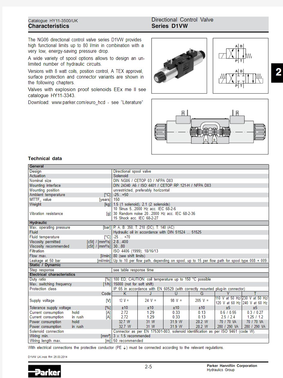
Technical data
With electrical connections the protective conductor (PE W ) must be connected according to the relevant regulations.
The NG06 directional control valve series D1VW provides high functional limits up to 80 l/min in combination with a very low, energy-saving pressure drop.
A wide variety of spool options allows to design an un-limited number of hydraulic circuits.
Versions with 8 watt coils, position control, A TEX approval, surface protection and connector variants are shown in the following chapters.
Valves with explosion proof solenoids EEx me ll see catalogue HY11-3343.
Download: https://www.360docs.net/doc/d718505956.html,/euro_hcd - see “Literature”
Directional Control Valve Series D1VW
Catalogue HY11-3500/UK
2
Ordering Code
Directional control Wet pin armature 3-chamber valve Spool position
Spool type
Size DIN NG063)
DC only
D 1W
V
Directional Control Valve Series D1VW
Catalogue HY11-3500/UK
2
Seals
Solenoid option Solenoid
connector as per EN 175301-803,without plug
(other connectors are available for D1MW Series)
Solenoid voltage
Further spool types, solenoid voltages and connectors on request.
Ordering Code
Code Seals N NBR V FPM
Code
Solenoid option
omit
Standard solenoid with
manual override
T without manual override S2
3)
Soft shift orifice size 0.5 mm.S3 3)Soft shift orifice size 0.75 mm.4N 3)with lockable manual override
Code Voltage K 12 V =J 24 V =U 2)98 V =G 2)205 V =Y 110 V 50 Hz /120 V 60 Hz T
230 V 50 Hz /240 V 60 Hz
Design series
(not required for ordering)
W
Directional Control Valve Series D1VW
Catalogue HY11-3500/UK
2
Flow Curve Diagram
Flow curve
1
2345
67
8
9
13
14
Flow [l/min]
P r e s s u r e d r o p [b a r ]
4
8
12
16
20
02060
4080
24
12
10
11
All characteristic curves measured with HLP46 at 50 °C.1)
Only for pressure compensation, no high flow possible.
Directional Control Valve Series D1VW
Catalogue HY11-3500/UK
2
Flow [l/min]
10
20
30
40
50
60
70
80
90
050100150200250300350P r e s s u r e [b a r ]
082
009,011,102
003, 015,204, 205
010,021,022
101
P r e s s u r e [b a r ]
Flow [l/min]
The diagram below specifies the shift limits for valves with DC & AC solenoids. Valves with spool position “F” or “M” can only be operated up to 70 % of the limits. The specifications apply to a viscosity of 40 mm 2/s and bal-anced flow conditions. The shift limits can be considerably lower at unbalanced flow conditions. To avoid flow rates beyond the shift limits, a plug-in orifice can be inserted in the P-port.
Valve with standard DC solenoid
Valve with standard AC solenoid
Measured with HLP46 at 50 °C, 95 % U nom and warm solenoids
Shift Limits
Measured with HLP46 at 50 °C, 90 % U nom and warm solenoids
Directional Control Valve Series D1VW
Catalogue HY11-3500/UK
2
300
200250100501503500
20
10
30
40
50
60
7080S u p p l y p r e s s u r e [b a r ]
Flow [l/min]
001,004
081,082
009
002
020D
300
200250100501503500
20
10
30
40
50
60
7080S u p p l y p r e s s u r e [b a r ]
Flow [l/min]
002,020
030
009,102101
001,004,081
Response times D1VW Standard and Soft Shift [ms]
Step response times were obtained under the following conditions: HLP46 at 50 °C with the valve operating at nominal pressure and flow. Pub-lished response times are nominal and may vary with spool, flow, pressure and temperature.
Acceleration for orifice size 0.75, code “S3” (measured against a standard valve)
Shift Limits / Response Times
For even softer shifting, the proportional spools 081, 082, 101 and 102 can be used.
Shift limit diagram - Soft shift with 1 DC solenoid
Shift limit diagram - Soft shift with 2 DC solenoids
Measured with HLP46 at 50 °C, 90 % U nom and warm solenoids.
The lower value applies to small flow rates and low pressure, the upper value to high flow rates and high pressure.
Directional Control Valve Series D1VW
Catalogue HY11-3500/UK
2
Dimensions
The space necessary to remove the plug per EN 175301-803, design type AF is at least 15 mm. The torque for the screw M3 of the plug has to be 0.5 to 0.6 Nm.
C, D -style
Option 4N, with lockable manual override (available for all styles, DC only)
C, D -style
H, K, M -style
Interface EN 175301-803, DC solenoid B, E, F -style
H, K, M -style
Interface EN 175301-803, AC solenoid B, E, F -style
Catalogue HY11-3500/UK
2
Notes