西门子变频器G120安全配置

Configuration and project engineering
1.0 Parameterizing the safety functions integrated in the drive
All of the steps necessary to commission the safety functions being used
are explained in this section.
The following describes how the safety functions are commissioned online.
Note
Offline commissioning is possible, however then slight deviations when
configuring must be observed. Further information on this topic is provided in the
Safety Function Manual (FHS), in Edition 01/1013 /1/.
Only the screen forms are shown here where changes have to be made.
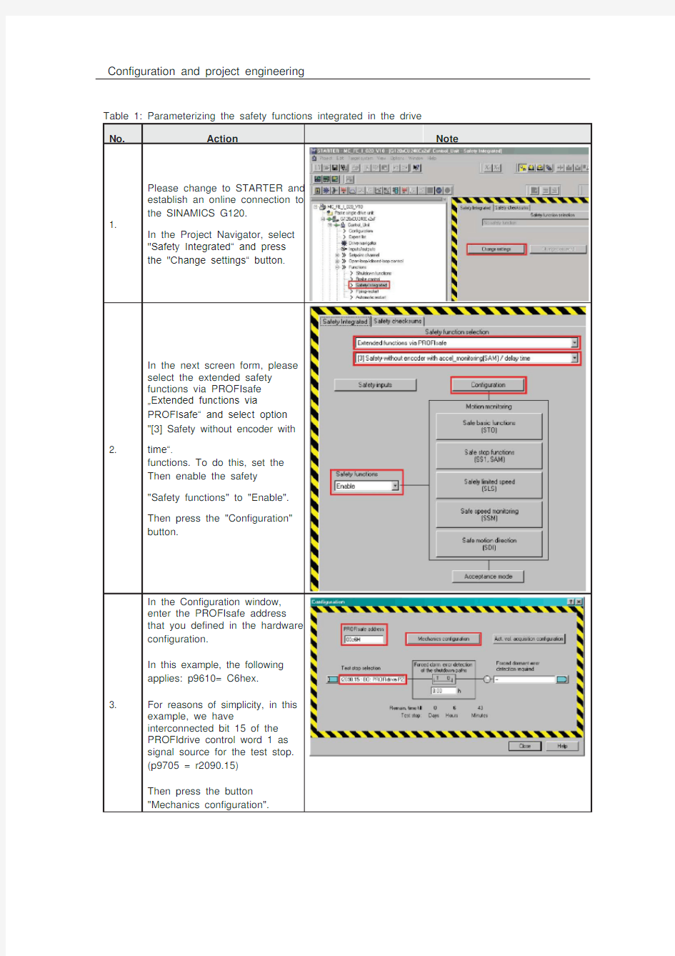
Table 1: Parameterizing the safety functions integrated in the drive
No. Action Note Please change to STARTER and
establish an online connection to
1. the SINAMICS G120.
In the Project Navigator, select "Safety Integrated“ and press the "Change settings“ button.
In the next screen form, please select the extended safety functions via PROFIsafe …Extended functions via PROFIsafe“ and select option
acc el_monitoring(SAM) / delay
"[3] Safety without encoder with
2. time“.
functions. To do this, set the
Then enable the safety
"Safety functions" to "Enable".
Then press the "Configuration"
button.
In the Configuration window,
enter the PROFIsafe address
that you defined in the hardware
configuration.
In this example, the following
applies: p9610= C6hex.
3. For reasons of simplicity, in this
example, we have
interconnected bit 15 of the
PROFIdrive control word 1 as
signal source for the test stop.
(p9705 = r2090.15)
Then press the button
"Mechanics configuration".
No. Action Note In this particular example, a
motor with two pole pairs is
used; therefore for p9522[0]
"Number of motor revolutions x
4. pole pair number", enter the
number 2.
Close the screen form using
"Close".
In the safety overview window,
please press button "Safe stop
5. functions (SS1, SAM)" to accept
the setting for the safe
acceleration monitor.
Here, please change "Delay time
SS1/STOP B --> STO active“ to
500ms.
This means that after an SS1 or
6. STOP B has been selected, in this particular example, STO is activated as subsequent state after 500 ms.
Then close the screen form using "Close".
No. Action Note In the safety overview window,
7. now please press button "Safely
limited speed (SLS)".
For this example, please set a
value of 750 rpm for SLS level 1.
8. Please select "STOP A" as stop
response.
Then press the "Close" button.
No. Action Note The parameters must now be
copied. To do this please press
9.
the "Copy parameters" button.
Then click on the "Activate
settings" button.
You are subsequently prompted
10. default pass word is "0". Change
to change the password. The
the password to "1".
Data is now copied from RAM to
11. ROM by pressing the "Yes"
button.
12. Then go offline
13. Now please carry out a power on
Power OFF/ON reset of the drive.
Then go online again, load the
14. project into the PG/PC and save
it.
15.After power on, messages C01697 (test stop), C1796 (wait for communication) and C07991 (motor data identification pending) are active. These alarms represent a normal response, as the F program for