中英文文献翻译—运动型7速双离合器变速器系统
附录
附录A外文文献原文
7-Speed Dual Clutch Transmission System for Sporty Application ABSTRACT:With its 7-speed dual clutch transmission, ZF has introduced an innovative transmission for sporty applications. The close ratios combined with extremely spontaneous drive behavior makes it an ideal transmission for sporty applications. This article describes the compact gear set with lubrication by injection for improving the level of efficiency and increasing the engine-speed-strength, the dual clutch unit as well as the hydraulic control unit, which is based on the pre-control principle, are also described in detail. The hy-draulic control principle provides the option of a hydraulic cruise mode in the event of an electronics failure. In addition to the transmission design, functional features that also highlight the sporty character of the transmission are described in detail.
Key words: Automatic transmission; Dual clutch; Vehicle connection; Efficiency
1 Introduction
When it comes to the field of automatic transmissions, dual clutch systems currently represent the benchmark in terms of spontaneity and sportiness. In this type of transmission, which is based on a countershaft transmission, these advantages are combined with a very direct "vehicle connection", high rpm performance, and excellent transmission efficiency.
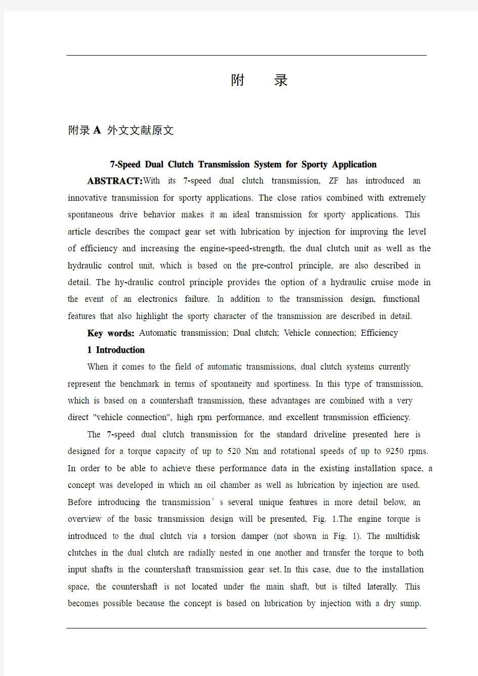
The 7-speed dual clutch transmission for the standard driveline presented here is designed for a torque capacity of up to 520 Nm and rotational speeds of up to 9250 rpms. In order to be able to achieve these performance data in the existing installation space, a concept was developed in which an oil chamber as well as lubrication by injection are used. Before introducing the transmission′s several unique features in more detail below, an overview of the basic transmission design will be presented, Fig. 1.The engine torque is introduced to the dual clutch via a torsion damper (not shown in Fig. 1). The multidisk clutches in the dual clutch are radially nested in one another and transfer the torque to both input shafts in the countershaft transmission gear set. In this case, due to the installation space, the countershaft is not located under the main shaft, but is tilted laterally. This becomes possible because the concept is based on lubrication by injection with a dry sump.
On the one hand, lubrication by injection improves heat removal, on the other, there are no noticeable losses due to the gears splashing in the oil pan. The oil is supplied to the transmission via an internal gear pump which is driven by a spur gear train behind the dual clutch. With the help of a spur gear train, the drive unit has the advantage that, via different gear ratio phases and depending on the intended use, the flow rate and the max. speed of the pump can be adapted. An additional advantage is that based on theresulting I proved installation space, an optimal ratio between the pump width and the pump diameter can be achieved for the pump′s level of efficiency. The hydraulic control unit is arranged under the gear set. The hydraulic unit supplies the clutch, based on need, with pressure and cooling oil as well as shift actuators. The latter are arranged laterally to the gear set and work with double-acting cylinders. The sensor for detecting the position of the gearshifts is attached directly onto the four gearshifts. The transmission has an external control unit.
Fig.1Overview dual clutch transmission (DCT)
2 Seven speeds with sophisticated stepping-a concept for extrme sporti- ness
The gear set concept of the dual clutch transmission introduced here was developed in house taking into consideration the following requirements:
High power density
High speed endurance strength up to 9250 rpm Variability and modular design
Representation of transmission-ratio spreads of about 4.7 and 6.8 with 7 speeds
Use of existing synergies for manual transmissions
After extensive systematic development of the gear set in which many thousands of variants were produced and compared, the gear set concept that is illustrated in Fig. 2 is the final variant and the ideal concept for achieving the goals specified.
The gear set selected is based on the constant drive concept and consists of two concentric drive shafts each of which are driven by one of the two multidisk clutches in the
Fig.2Gear set scheme of 7D variant
dual clutch, two countershafts also concentric to one another, a main shaft and an output shaft. The gear ratios are engaged by the four synchronizer units A/B, C/D, E/F, and G/H, which are arranged on the main shaft and on the hollow countershaft and these are connected to the loose wheels or the adjacent shafts. An important feature in the gear set is the connectability of both countershafts through the C/D synchronizer unit. In the D shift position, the gear ratios selected in this way can be doubly used which reduces construction costs compared to conventional dual clutch gear sets. Similarly, this feature is used in first gear because then the vehicle is started up using the more powerful K1 clutch. Because of this dual use of the last gear level in the transmission for the first and second gear, the desired ratio step 1-2 is achieved through the transmission ratios of both constant drive phases.
The use of the K1 clutch for starting up in first gear results inevitably in the direct gear also being assigned to the odd subsection. In this case, the fifth and seventh gears can be selected as a direct drive. With this feature, it was possible to develop a modular gear set which, on just a few changes,contains two different transmission gear ratio variants with fundamentally different characters.
For the first version, with an overall spread of about 4 . 7 , the seventh gear is selected as a direct gear (called the 7D variant). Fig. 2 shows the relevant gear set diagram with the performance flows in all speeds. Due to its sophisticated gear steps, this transmission is highly suitable for very sporty vehicles that need only a "little" transmission stepping due
to the high rotating engine. Optimal tractive power can be provided at any time during
vehicle operation.
The second version is based on the 7D variant, however, fifth gear was selected as the direct drive. When maintaining the torque multiplication ratio and in adapting the transmission ratio of several lower gear levels, you get the 5D variant with a considerably higher transmission-ratio spread for vehicles with increased comfort demands and simultaneously reduced consumption.
Fig. 3 illustrates the design of the 7D variant. The main similarity with existing manual transmissions for standard transmissions is noticeable. Due to the compact gear set design, the sufficient shaft dimensioning and the favorable arrangement in proximity of the bearing of the high transmitting ratios, central bearing glasses were not necessary despite the proportionally large bearing clearance.Overall, only two housing bearing levels are necessary where the front level is located behind both constant gears. In addition, a very compact and inexpensive transmission design could be implemented based on the bearing concept selected, especially in the area of the hollow shaft.
Fig.3Sectional Drawing of 7D variant
3 The dual clutch
The central module of this highly topical transmission concept is the wet dual clutch. With a broad spectrum of technical features, it implements the functional provisions of the transmission control unit and thus distinguishes the special character of this transmission concept.
Very fast delay times, low inertia and good, comfortable friction value progressions facilitate, very sporty handling with highly dynamic gear shifting and comfortable cruising at a high level of efficiency. The dual clutch placed directly on the transmission input accepts the engine torque from thtorsion damper and feeds it to one of the two subsections, depending on the situation.
Safety considerations have led to a "normall open" design.
The radial arrangement of the multidisk pack age represents the best combination of performanc and installation space need, Fig. 4.
Fig.4Dual clutch
Careful lining and oil selection as well as intensive enhancement of this tribological system are the requirements for comfort and performance of this clutch throughout its service life.
Through intense testing and detailed calculations, it was possible to achieve a very high therma loading capacity. As part of the process, the lining type, dimensioning, and grooving as well as equal distribution of thermal load and oil flow in the multidisk package are decisive design features.
Low torque drag even with low temperatures as well as high speed endurance strength support comfort and a high level of sportiness, but are also important safety requirements.
Rotating, centrifugal force-compensating clutch cylinders with hysteresis optimized gaskets make the clutches easy to control. Integrated plate springs reliably accept rapid piston resetting even at high speeds.
In the case of an open clutch, only transmission input shafts with very low additional mass inertia are used. This supports rapid synchronizing sequences and a long service life of the synchronizer units.
4 The hydraulic control unit
In the present dual clutch transmission, the hydraulic control unit fulfills the following tasks:
Actuating the dual clutch
Shifting the gearshifts, i. e. engaging/synchronizing the gear
Cooling the dual clutch
Gear lubrication
Emergency stop function in case of complete failure of transmission electronics
Several features in the hydraulic control unit as well as criteria for the selection of the control concept are going to be described in more detail below.
4.1 Performance
The use of the dual clutch transmission in sporty vehicles demands high performance from the hydraulic control unit, especially with regard to the first two tasks because the timely "handling" of these tasks come into play in gear shifting and gear shifting times.
That is why particular value is placed on the selection of the right control unit concept as part of the system design. During the decision process, the choice was made, in principle, between two concepts, Fig. 5.
Fig.5Control concept direct control / precontrol
Precontrol of the valves
Direct control of the valves (so-called cartridge valves)
In case of direct control, the valve that is used for pressure control, e.g. a clutch, is directly connected to the power-generating proportional solenoids and provides the main pressure to the corresponding clutch pressure.
The precontrol uses the pressure that is supplied by a pressure controller, for example, to actuate an additional valve that supplies the clutch pressure from the main pressure.
To assess the performance of both concepts, a larger number of compared measurements were performed with different systems, of which two systems shall be considered here:
ZF hydraulic control unit with precontrol for DCT standard drive
Comparative hydraulic control unit with direct control
A reference clutch was used as the clutch to engage. Criteria for assessing the performance were (see also Fig. 6):
Fig.6Delay, increase/rise, and fall times. Red curve: Power /Electric current. Green curve: Clutch
pressure
Delay time, 1 to 4
Time of step response until clutch inflation pressure, 1 to 2
Time of the step response up to 90% of the main pressure 1 to 3
Time of pressure drop (emptying times), 5 to 6
Fig. 6 shows, as an example, the times for a transmission oil temperature of + 20°C to be reached. One notices that the direct control first in dicates a lower delay time (14.3 ms) compared to the precontrol (30.1 ms), see also time of brand 1to 4.
For increase to clutch inflation pressure or to 90% of the main pressure shows, however, the advantage of the precontrolled system (see also summarizing tab 1).
Emptying times, also present a disadvantage for direct control. Trans-mission oil temperature of -20°C also show comparable results for step responses and fall times.
All of the tests support the statement that direct control has an advantageous effect with small oil volumes. However, if large oil volumes have to be transported, precontrol valves are to be preferred due to larger opening cross-sections.
4.2 Operational safety
Operational safety is determined essentially due to the soiling tendency because the so-called silting can lead to the valves getting jammed. Provocation tests with transmission-specific environmental conditions (dirty oil) demonstrated the influences of soiling on the characteristic curves. Technical, trouble-free characteristic curve progressions could be illustrated only with a high dither amplitude in valve actuation, which leads, in turn, to increased valve wear-and-tear due to the micro movements that it causes. The increased tendency toward soiling can result needing a fine filter.
4.3 Costs
In addition to the delay time comparison as well as assessing the operational safety, the costs were relevant for a final evaluation. The compari son with regard to the hydraulic and electro-mag netic components shows that a precontrol system has cost benefits compared to a direct control system. Added to this are the higher flows with the actuation of direct control valves, which, in turn, result in a more expensive TCU. Furthermore, in opting for precontrol, ZF is able to "pool" together pressure controllers in large quantities because these, too, are used in the automatic ZF planetary gear set.
4.4 Emergency stop function
In case there is a complete outage in the transmission electronics, a hydraulic emergency stop function is actuated in the transmission. The clutch that is pressurized with a larger amount of pressure in the event of a system outage will continue to be pressurized. This condition is maintained until an adjustable engine speed threshold is achieved, then the clutch opens in order to prevent the engine from being choked. It is not possible to re-start this system.
5 Sporty functions
For function developers, the dual clutch transmission offers the opportunity to combine the comfort of a stepped automatic transmission with the dynamics and sportiness of a countershaft transmission. Connected, therefore, are typical " catalog values," such as time from zero to 100 kilometers per hour or the time from 80 to 120 kilometers per hour with correspondingly fast kick-down shifting, but also subjective acceleration sensitivity during a shifting sequence where the purist among the manual transmission drivers still wants to feel that jolt of acceleration.
One function especially designed for the dual clutch transmission in sports cars is the "race start"function. The race start is a function used to achieve optimal acceleration from a
standstill, i.e. in the shortest time from 0 to 100 km/h. The sequence progresses as follows: The engine is brought to a suitably high rpm with the clutch engaged in first gear. The driver simultaneously actuates the brakes with the lef foot so that the clutch can already be lightly engaged and the gas pedal (full throttle) in order to bring the vehicle up to the target speed. By simultaneously pressing and holding an operating element, such as the selector lever or a push button on the steering wheel, the race start intention is conveyed to the system, the engine speed adjusted and the start up prevented until the driver releases the brake. During the race start, the clutch is closed under the control of the wheel slip with which the optimal acceleration is achieved and by exploiting the dynamic engine torque (inertia torque). The entire procedure progresses automatically once the driver releases so that even an inexperienced driver
can achieve the best possible drive performance figures. Obviously, the driver can cancel the procedure by removing his/her foot from the gas pedal or touching the brakes. Also, the system recognizes when the street conditions do not permit a race start, such as wet roads, for example. Due to the optimal start-up and a shifting sequence into second gear free of traction interruption (see also sports shifting), the race start function enables the acceleration time of 0 to 100 km/h to be improved by an average of 0.2 sec compared to a car with a manual transmission. At the same time, this functionality helps avoid improper use and resulting clutch overload.
The top chart in Fig. 7 illustrates the engine and transmission input shaft speed, the lower chart shows the vehicle′s longitudinal acceleration. Starting with a cranking speed of 6,800 rpm, the clutch begins to close, which leads to an engine pressure up to about 4,000 rpm. The dynamic engine torque used to achieve this results in an acceleration of 0.7-0.9 g. In the process, noticeable vibrations in the transmission input shaft speed signal develop due to the wheel slip regulation. After about 1.2 sec, the vehicle is accelerated only by the engine torque with approx. 0.5 g. It must be mentioned here that this test was performed using a vehicle with very high traction. In most cases, a starting speed of only up to about 4,000 rpm is reasonable.
A further function developed for the dual clutch transmission is so-called sports shifting. This is described in more detail below.
In general, a gear-shift change by the driver is only perceived acoustically by the change in the engine speed. The transition from the acceleration level of the original gear to
Fig.7Measurement of a race star
the new gear should be made smoothly and continuously. This also corresponds to the standard shifting sequences in auto-matic and dual clutch transmissions. However, many drivers of sporty cars wish that they had the option of both distinctive comfort shifting sequences as well as sporty shifting sequences, which, besides the haptic response (acceleration jolt), also have an acceleration advantage as a result. To this end, the dynamic engine torque can also be used again. The requirement for this is the torque capacity of the dual clutch which has to be able to transmit this torque increase. As the possible torque increase depends on the gradients of the engine speed, this can be used particularly effectively in shifting gears with a large speed difference with the target gear (large ratio spread/ratio step), which is why the gear changes 1-2, 2-3, and 3-4 are offered. In the process, sports shifting from the frst to second gear can serve as a supplement to the ace start for improving the acceleration time from to 100 km/h. As the use of the dynamic torque is pure application topic, we distinguish, as a rule,between three shifting systems. Fig. 8 illustrates he stylized differences and features between the hifting systems, Fig. 9 shows an original measurement from a prototype vehicle.
The top chart shows the respective engine and ransmission speed, the bottom chart shows the orques from both clutches. The bottom line in the hart represents the clutch from the target gear that is used to achieve the torque increase during engine sp eed adjustment
and thereby acceleration gains.
中英文文献翻译
毕业设计(论文)外文参考文献及译文 英文题目Component-based Safety Computer of Railway Signal Interlocking System 中文题目模块化安全铁路信号计算机联锁系统 学院自动化与电气工程学院 专业自动控制 姓名葛彦宁 学号 200808746 指导教师贺清 2012年5月30日
Component-based Safety Computer of Railway Signal Interlocking System 1 Introduction Signal Interlocking System is the critical equipment which can guarantee traffic safety and enhance operational efficiency in railway transportation. For a long time, the core control computer adopts in interlocking system is the special customized high-grade safety computer, for example, the SIMIS of Siemens, the EI32 of Nippon Signal, and so on. Along with the rapid development of electronic technology, the customized safety computer is facing severe challenges, for instance, the high development costs, poor usability, weak expansibility and slow technology update. To overcome the flaws of the high-grade special customized computer, the U.S. Department of Defense has put forward the concept:we should adopt commercial standards to replace military norms and standards for meeting consumers’demand [1]. In the meantime, there are several explorations and practices about adopting open system architecture in avionics. The United Stated and Europe have do much research about utilizing cost-effective fault-tolerant computer to replace the dedicated computer in aerospace and other safety-critical fields. In recent years, it is gradually becoming a new trend that the utilization of standardized components in aerospace, industry, transportation and other safety-critical fields. 2 Railways signal interlocking system 2.1 Functions of signal interlocking system The basic function of signal interlocking system is to protect train safety by controlling signal equipments, such as switch points, signals and track units in a station, and it handles routes via a certain interlocking regulation. Since the birth of the railway transportation, signal interlocking system has gone through manual signal, mechanical signal, relay-based interlocking, and the modern computer-based Interlocking System. 2.2 Architecture of signal interlocking system Generally, the Interlocking System has a hierarchical structure. According to the function of equipments, the system can be divided to the function of equipments; the system
变速器论文中英文对照资料外文翻译文献
中英文对照外文翻译 汽车变速器设计 我们知道,汽车发动机在一定的转速下能够达到最好的状态,此时发出的功率比较大,燃油经济性也比较好。因此,我们希望发动机总是在最好的状态下工作。但是,汽车在使用的时候需要有不同的速度,这样就产生了矛盾。这个矛盾要通过变速器来解决。 汽车变速器的作用用一句话概括,就叫做变速变扭,即增速减扭或减速增扭。为什么减速可以增扭,而增速又要减扭呢?设发动机输出的功率不变,功率可以表示为 N = w T,其中w是转动的角速度,T 是扭距。当N固定的时候,w与T是成反比的。所以增速必减扭,减速必增扭。汽车变速器齿轮传动就根据变速变扭的原理,分成各个档位对应不同的传动比,以适应不同的运行状况。 一般的手动变速器内设置输入轴、中间轴和输出轴,又称三轴式,另外还有倒档轴。三轴式是变速器的主体结构,输入轴的转速也就是发动机的转速,输出轴转速则是中间轴与输出轴之间不同齿轮啮合所产生的转速。不同的齿轮啮合就有不同的传动比,也就有了不同的转速。例如郑州日产ZN6481W2G型SUV车手动变速器,它的传动比分别是:1档3.704:1;2档2.202:1;3档1.414:1;4档1:1;5档(超速档)0.802:1。 当汽车启动司机选择1档时,拨叉将1/2档同步器向后接合1档
齿轮并将它锁定输出轴上,动力经输入轴、中间轴和输出轴上的1档齿轮,1档齿轮带动输出轴,输出轴将动力传递到传动轴上(红色箭头)。典型1档变速齿轮传动比是3:1,也就是说输入轴转3圈,输出轴转1圈。 当汽车增速司机选择2档时,拨叉将1/2档同步器与1档分离后接合2档齿轮并锁定输出轴上,动力传递路线相似,所不同的是输出轴上的1档齿轮换成2档齿轮带动输出轴。典型2档变速齿轮传动比是2.2:1,输入轴转2.2圈,输出轴转1圈,比1档转速增加,扭矩降低。 当汽车加油增速司机选择3档时,拨叉使1/2档同步器回到空档位置,又使3/4档同步器移动直至将3档齿轮锁定在输出轴上,使动力可以从轴入轴—中间轴—输出轴上的3档变速齿轮,通过3档变速齿轮带动输出轴。典型3档传动比是1.7:1,输入轴转1.7圈,输出轴转1圈,是进一步的增速。 当汽车加油增速司机选择4档时,拨叉将3/4档同步器脱离3档齿轮直接与输入轴主动齿轮接合,动力直接从输入轴传递到输出轴,此时传动比1:1,即输出轴与输入轴转速一样。由于动力不经中间轴,又称直接档,该档传动比的传动效率最高。汽车多数运行时间都用直接档以达到最好的燃油经济性。 换档时要先进入空档,变速器处于空档时变速齿轮没有锁定在输出轴上,它们不能带动输出轴转动,没有动力输出。 一般汽车手动变速器传动比主要分上述1-4档,通常设计者首先确定最低(1档)与最高(4档)传动比后,中间各档传动比一
关于力的外文文献翻译、中英文翻译、外文翻译
五、外文资料翻译 Stress and Strain 1.Introduction to Mechanics of Materials Mechanics of materials is a branch of applied mechanics that deals with the behavior of solid bodies subjected to various types of loading. It is a field of study that i s known by a variety of names, including “strength of materials” and “mechanics of deformable bodies”. The solid bodies considered in this book include axially-loaded bars, shafts, beams, and columns, as well as structures that are assemblies of these components. Usually the objective of our analysis will be the determination of the stresses, strains, and deformations produced by the loads; if these quantities can be found for all values of load up to the failure load, then we will have obtained a complete picture of the mechanics behavior of the body. Theoretical analyses and experimental results have equally important roles in the study of mechanics of materials . On many occasion we will make logical derivations to obtain formulas and equations for predicting mechanics behavior, but at the same time we must recognize that these formulas cannot be used in a realistic way unless certain properties of the been made in the laboratory. Also , many problems of importance in engineering cannot be handled efficiently by theoretical means, and experimental measurements become a practical necessity. The historical development of mechanics of materials is a fascinating blend of both theory and experiment, with experiments pointing the way to useful results in some instances and with theory doing so in others①. Such famous men as Leonardo da Vinci(1452-1519) and Galileo Galilei (1564-1642) made experiments to adequate to determine the strength of wires , bars , and beams , although they did not develop any adequate theo ries (by today’s standards ) to explain their test results . By contrast , the famous mathematician Leonhard Euler(1707-1783) developed the mathematical theory any of columns and calculated the critical load of a column in 1744 , long before any experimental evidence existed to show the significance of his results ②. Thus , Euler’s theoretical results remained unused for many years, although today they form the basis of column theory. The importance of combining theoretical derivations with experimentally determined properties of materials will be evident theoretical derivations with experimentally determined properties of materials will be evident as we proceed with
文献翻译英文原文
https://www.360docs.net/doc/d89030458.html,/finance/company/consumer.html Consumer finance company The consumer finance division of the SG group of France has become highly active within India. They plan to offer finance for vehicles and two-wheelers to consumers, aiming to provide close to Rs. 400 billion in India in the next few years of its operations. The SG group is also dealing in stock broking, asset management, investment banking, private banking, information technology and business processing. SG group has ventured into the rapidly growing consumer credit market in India, and have plans to construct a headquarters at Kolkata. The AIG Group has been approved by the RBI to set up a non-banking finance company (NBFC). AIG seeks to introduce its consumer finance and asset management businesses in India. AIG Capital India plans to emphasize credit cards, mortgage financing, consumer durable financing and personal loans. Leading Indian and international concerns like the HSBC, Deutsche Bank, Goldman Sachs, Barclays and HDFC Bank are also waiting to be approved by the Reserve Bank of India to initiate similar operations. AIG is presently involved in insurance and financial services in more than one hundred countries. The affiliates of the AIG Group also provide retirement and asset management services all over the world. Many international companies have been looking at NBFC business because of the growing consumer finance market. Unlike foreign banks, there are no strictures on branch openings for the NBFCs. GE Consumer Finance is a section of General Electric. It is responsible for looking after the retail finance operations. GE Consumer Finance also governs the GE Capital Asia. Outside the United States, GE Consumer Finance performs its operations under the GE Money brand. GE Consumer Finance currently offers financial services in more than fifty countries. The company deals in credit cards, personal finance, mortgages and automobile solutions. It has a client base of more than 118 million customers throughout the world
双离合器自动变速器的设计毕业设计
哈尔滨工业大学华德应用技术学院毕业设计 摘要 双离合器自动变速器由电控机械式自动变速器发展而来,它综合了液力机械自动变速器(AT)和电控机械自动变速器(AMT)的优点,能够实现动力换挡、减少了换档时间、提高了换档品质、极大地提高了汽车的舒适性和操纵性。 本设计以双离合器式自动变速器的结构和工作原理为基础,针对干式双离合器自动变速器的设计方法,分析了各种不同变速器的布置方案并选定了本变速器的最终布置方案。对变速器中的主要零件包括齿轮形式、换挡结构形式作了阐述并进行了选择并对变速器的传动比的范围、中心距做初步的选择和设计。对变速器中的齿轮的模数、压力角、螺旋角、进行了选择并计算出齿轮其他的相关参数和对齿轮的校核。对轴的结构尺寸进行设计和轴承的选用并对其进行了校核。 关键词:双离合器;自动变速器;传动比;齿轮;轴 ABSTRACT DCT duo to Mechanical Transmission.Itinherits the advantages of Automatic Transmission(AT) and Automated Mechanical Transmission (AMT).It has the ability of power shifing that can reduce shift time andimprove shift quality.And the comfort and maneuverability of vehicle will be greatly improved. In this thesis,the study of dry type Dual Clutch Transmission is based on the Structural characteristics and working principle of DCT. For dry-type dual-clutch automatic transmission design, analyzed the layout of the various transmission options and selected the final layout of the transmission scheme. The major part of gear, including gear form, elaborated shift structure and make the choice and range I
英文文献翻译
中等分辨率制备分离的 快速色谱技术 W. Clark Still,* Michael K a h n , and Abhijit Mitra Departm(7nt o/ Chemistry, Columbia Uniuersity,1Veu York, Neu; York 10027 ReceiLied January 26, 1978 我们希望找到一种简单的吸附色谱技术用于有机化合物的常规净化。这种技术是适于传统的有机物大规模制备分离,该技术需使用长柱色谱法。尽管这种技术得到的效果非常好,但是其需要消耗大量的时间,并且由于频带拖尾经常出现低复原率。当分离的样本剂量大于1或者2g时,这些问题显得更加突出。近年来,几种制备系统已经进行了改进,能将分离时间减少到1-3h,并允许各成分的分辨率ΔR f≥(使用薄层色谱分析进行分析)。在这些方法中,在我们的实验室中,媒介压力色谱法1和短柱色谱法2是最成功的。最近,我们发现一种可以将分离速度大幅度提升的技术,可用于反应产物的常规提纯,我们将这种技术称为急骤色谱法。虽然这种技术的分辨率只是中等(ΔR f≥),而且构建这个系统花费非常低,并且能在10-15min内分离重量在的样本。4 急骤色谱法是以空气压力驱动的混合介质压力以及短柱色谱法为基础,专门针对快速分离,介质压力以及短柱色谱已经进行了优化。优化实验是在一组标准条件5下进行的,优化实验使用苯甲醇作为样本,放在一个20mm*5in.的硅胶柱60内,使用Tracor 970紫外检测器监测圆柱的输出。分辨率通过持续时间(r)和峰宽(w,w/2)的比率进行测定的(Figure 1),结果如图2-4所示,图2-4分别放映分辨率随着硅胶颗粒大小、洗脱液流速和样本大小的变化。
外文文献翻译:汽车的发展
The development of automobile As the world energy crisis and the war and the energy consumption of oil -- and are full of energy in one day someday it will disappear without a trace. Oil is not inresources. So in oil consumption must be clean before finding a replacement. With the development of science and technology the progress of the society people invented the electric car. Electric cars will become the most ideal of transportation. In the development of world each aspect is fruitful especially with the automobile electronic technology and computer and rapid development of the information age. The electronic control technology in the car on a wide range of applications the application of the electronic device cars and electronic technology not only to improve and enhance the quality and the traditional automobile electrical performance but also improve the automobile fuel economy performance reliability and emission spurification. Widely used in automobile electronic products not only reduces the cost and reduce the complexity of the maintenance. From the fuel injection engine ignition devices air control and emission control and fault diagnosis to the body auxiliary devices are generally used in electronic control technology auto development mainly electromechanical integration. Widely used in automotive electronic control ignition system mainly electronic control fuel injection system electronic control ignition system electronic control automatic transmission electronic control ABS/ASR control system electronic control suspension system electronic control power steering system vehicle dynamic control system the airbag systems active belt system electronic control system and the automatic air-conditioning and GPS navigation system etc. With the system response the use function of quick car high reliability guarantees of engine power and reduce fuel consumption and emission regulations meet standards. The car is essential to modern traffic tools. And electric cars bring us infinite joy will give us the physical and mental relaxation. Take for example automatic transmission in road can not on the clutch can achieve automatic shift and engine flameout not so effective improve the driving convenience lighten the fatigue strength. Automatic transmission consists mainly of hydraulic torque converter gear transmission pump hydraulic control system electronic control system and oil cooling system etc. The electronic control of suspension is mainly used to cushion the impact of the body and the road to reduce vibration that car getting smooth-going and stability. When the vehicle in the car when the road uneven road can according to automatically adjust the height. When the car ratio of height low set to gas or oil cylinder filling or oil. If is opposite gas or diarrhea. To ensure and improve the level of driving cars driving stability. Variable force power steering system can significantly change the driver for the work efficiency and the state so widely used in electric cars. VDC to vehicle performance has important function it can according to the need of active braking to change the wheels of the car car motions of state and optimum control performance and increased automobile adhesion controlling and stability. Besides these appear beyond 4WS 4WD electric cars can greatly improve the performance of the value and ascending simultaneously. ABS braking distance is reduced and can keep turning skills effectively improve the stability of the directions simultaneously reduce tyre wear. The airbag appear in large programs protected the driver and passengers safety and greatly reduce automobile in collision of drivers and passengers in the buffer to protect the safety of life. Intelligent electronic technology in the bus to promote safe driving and that the other functions. The realization of automatic driving through various sensors. Except some smart cars equipped with multiple outside sensors can fully perception of information and traffic facilities
10kV小区供配电英文文献及中文翻译
在广州甚至广东的住宅小区电气设计中,一般都会涉及到小区的高低压供配电系统的设计.如10kV高压配电系统图,低压配电系统图等等图纸一大堆.然而在真正实施过程中,供电部门(尤其是供电公司指定的所谓电力设计小公司)根本将这些图纸作为一回事,按其电脑里原有的电子档图纸将数据稍作改动以及断路器按其所好换个厂家名称便美其名曰设计(可笑不?),拿出来的图纸根本无法满足电气设计的设计意图,致使严重存在以下问题:(也不知道是职业道德问题还是根本一窍不通) 1.跟原设计的电气系统货不对板,存在与低压开关柜后出线回路严重冲突,对实际施工造成严重阻碍,经常要求设计单位改动原有电气系统图才能满足它的要求(垄断的没话说). 2.对消防负荷和非消防负荷的供电(主要在高层建筑里)应严格分回路(从母线段)都不清楚,将消防负荷和非消防负荷按一个回路出线(尤其是将电梯和消防电梯,地下室的动力合在一起等等,有的甚至将楼顶消防风机和梯间照明合在一个回路,以一个表计量). 3.系统接地保护接地型式由原设计的TN-S系统竟曲解成"TN-S-C-S"系统(室内的还需要做TN-C,好玩吧?),严格的按照所谓的"三相四线制"再做重复接地来实施,导致后续施工中存在重复浪费资源以及安全隐患等等问题.. ............................(违反建筑电气设计规范等等问题实在不好意思一一例举,给那帮人留点混饭吃的面子算了) 总之吧,在通过图纸审查后的电气设计图纸在这帮人的眼里根本不知何物,经常是完工后的高低压供配电系统已是面目全非了,能有百分之五十的保留已经是谢天谢地了. 所以.我觉得:住宅建筑电气设计,让供电部门走!大不了留点位置,让他供几个必需回路的电,爱怎么折腾让他自个怎么折腾去.. Guangzhou, Guangdong, even in the electrical design of residential quarters, generally involving high-low cell power supply system design. 10kV power distribution systems, such as maps, drawings, etc. low-voltage distribution system map a lot. But in the real implementation of the process, the power sector (especially the so-called power supply design company appointed a small company) did these drawings for one thing, according to computer drawings of the original electronic file data to make a little change, and circuit breakers by their the name of another manufacturer will be sounding good design (ridiculously?), drawing out the design simply can not meet the electrical design intent, resulting in a serious following problems: (do not know or not know nothing about ethical issues) 1. With the original design of the electrical system not meeting board, the existence and low voltage switchgear circuit after qualifying serious conflicts seriously hinder the actual construction, often require changes to the original design unit plans to meet its electrical system requirements (monopoly impress ). 2. On the fire load and fire load of non-supply (mainly in high-rise building in) should be strictly sub-loop (from the bus segment) are not clear, the fire load and fire load of non-qualifying press of a circuit (especially the elevator and fire elevator, basement, etc.
英文文献及中文翻译
毕业设计说明书 英文文献及中文翻译 学院:专 2011年6月 电子与计算机科学技术软件工程
https://www.360docs.net/doc/d89030458.html, Overview https://www.360docs.net/doc/d89030458.html, is a unified Web development model that includes the services necessary for you to build enterprise-class Web applications with a minimum of https://www.360docs.net/doc/d89030458.html, is part of https://www.360docs.net/doc/d89030458.html, Framework,and when coding https://www.360docs.net/doc/d89030458.html, applications you have access to classes in https://www.360docs.net/doc/d89030458.html, Framework.You can code your applications in any language compatible with the common language runtime(CLR), including Microsoft Visual Basic and C#.These languages enable you to develop https://www.360docs.net/doc/d89030458.html, applications that benefit from the common language runtime,type safety, inheritance,and so on. If you want to try https://www.360docs.net/doc/d89030458.html,,you can install Visual Web Developer Express using the Microsoft Web Platform Installer,which is a free tool that makes it simple to download,install,and service components of the Microsoft Web Platform.These components include Visual Web Developer Express,Internet Information Services (IIS),SQL Server Express,and https://www.360docs.net/doc/d89030458.html, Framework.All of these are tools that you use to create https://www.360docs.net/doc/d89030458.html, Web applications.You can also use the Microsoft Web Platform Installer to install open-source https://www.360docs.net/doc/d89030458.html, and PHP Web applications. Visual Web Developer Visual Web Developer is a full-featured development environment for creating https://www.360docs.net/doc/d89030458.html, Web applications.Visual Web Developer provides an ideal environment in which to build Web sites and then publish them to a hosting https://www.360docs.net/doc/d89030458.html,ing the development tools in Visual Web Developer,you can develop https://www.360docs.net/doc/d89030458.html, Web pages on your own computer.Visual Web Developer includes a local Web server that provides all the features you need to test and debug https://www.360docs.net/doc/d89030458.html, Web pages,without requiring Internet Information Services(IIS)to be installed. Visual Web Developer provides an ideal environment in which to build Web sites and then publish them to a hosting https://www.360docs.net/doc/d89030458.html,ing the development tools in Visual Web Developer,you can develop https://www.360docs.net/doc/d89030458.html, Web pages on your own computer.
二轴式手动变速器外文翻译
外文翻译 文章出处《Tribology International》, 2009, 42(5):714-723 译文: 有限元热分析的陶瓷离合器 1 引言 磨料空转车辆离合器是力封闭联轴器。扭矩和高速传输被压紧表面之间产生的摩擦力所保证。应用陶瓷是因为它作为摩擦介质具有好耐热和耐磨损性能,提供了机会以驱动更高的压力,以及一个低的密度。因此,一个提功率密度启用了一个平行的最小化建筑空间。 测量使用陶瓷饰面离合器盘的第一个原型在卡尔斯鲁厄大学的一个实验室专门从事客车驱动系统进行了测试执行。在分析过程中的有限元(FE)模型是将与测量数据和测量条件的知识所构成。计算的目的是要确定在离合器盘上温度的分布以及环境中的在每一时刻的及时测量目。至关重要的是熟悉的温度范围,为了检验该系统的耐磨特性。因此,重要信息从测量数据中得出。在临界负载的情况下,预计最高温度必须在时间和空间上进行预测,为保护接近发热体的位置测量工具的。 本研究的目的是分析和修改该离合器系统通过改进,以提供更好的工作条件热传导和系统或增加转化成摩擦热的能量的对流。此外,人们希望找到更有效的更好的离合器系统设计方案。 计算是由宇宙星空的设计的软件进行的。在模型开发阶段,非常谨慎,必须采取几何元素,选择适当的简化尺寸,并且由于正确调整的时间步长大量的硬件要求瞬态计算。热物性参数的改变,如表面热对流化系数和热负荷,必须考虑到到在一个持续的基础上在时间和地点方面。离合器系统的分析测试这两方面,只能通过加热隔板连接的两个独立的模型来管理,根据该假说认为,接触温度必须是在两个相同的双方,同时他们要有适当接触,其价值需通过迭代来进行调整。计算显示,该热分区按周期变化,它沿不同的内,外接触环。在不同的冷却特性下,在陶瓷和钢之间的结果是不同的,热流从陶瓷侧面向钢侧流动。此热流也通过迭代确定;它的价值也改变了周期和不同沿着所述内和外接触环。 2 采用工程陶瓷作为摩擦材料的第一个原型机 这款检查过的离合器盘是根据“特定的陶瓷”产品而开发的,此材料的研发过程在流程在卡尔斯鲁厄大学的Institute for Product Development (IPEK)杂志上发表过。此开发过程已经具有的可能性,用于连接到一个真实的传动轴;甚至,它为面板有一个好的初始行为起到一个很好的缓冲作用。磨料配件必须符合以下基本要求: