机械原理课程设计(牛头刨床机构)
机械原理课程设计说明书
——牛头刨床传动机构的设计及其运动分析
设计者:
班级:
学号:
指导教师:
日期:2010年6月28日
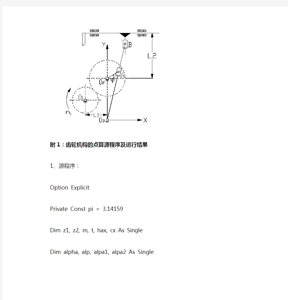
机构示意图:
附1:齿轮机构的点算源程序及运行结果
1、源程序:
Option Explicit
Private Const pi = 3.14159
Dim z1, z2, m, t, hax, cx As Single
Dim alpha, alp, alpa1, alpa2 As Single
Dim d1, d2, x1, x2, ha1, ha2, hf1, hf2, h1, h2 As Single
Dim db1, db2, da1, da2, df1, df2, a, e, s1, s2, sa1, sa2 As Single
Private Sub command1_click() '清零z1 = 0
z2 = 0
m = 0
alpha = 0
hax = 0
cx = 0
Text1.Text = " "
Text2.Text = " "
Text3.Text = " "
Text4.Text = " "
Text5.Text = " "
Text6.Text = " "
Text7.Text = " "
Text8.Text = " "
Text9.Text = " "
Text10.Text = " "
Text11.Text = " "
Text12.Text = " "
Text13.Text = " "
Text14.Text = " "
Text15.Text = " "
Text16.Text = " "
Text17.Text = " "
Text18.Text = " "
Text19.Text = " "
Text20.Text = " "
Text21.Text = " "
Text22.Text = " "
End Sub
Private Sub command2_click()
z1 = Val(InputBox("请输入第一个齿轮的齿数"))
z2 = Val(InputBox("请输入第二个齿轮的齿数"))
m = Val(InputBox("请输入齿轮的模数"))
alpha = Val(InputBox("请输入齿轮的压力角"))
hax = Val(InputBox("请输入齿轮的齿顶高系数"))
cx = Val(InputBox("请输入齿轮的顶隙系数"))
t = 180# / pi
alp = alpha / t '角度转化成弧度
End Sub
Private Sub Command3_Click()
d1 = m * z1
d2 = m * z2
x1 = (17 - z1) / 17
x2 = 0 - x1
ha1 = (hax + x1) * m
ha2 = (hax + x2) * m
hf1 = (hax + cx - x1) * m
hf2 = (hax + cx - x2) * m
h1 = (2 * hax + cx) * m
h2 = (2 * hax + cx) * m
da1 = d1 + 2 * ha1
da2 = d2 + 2 * ha2
df1 = d1 - 2 * hf1
df2 = d2 - 2 * hf2
a = 0.5 * m * (z1 + z2)
db1 = d1 * Cos(alp)
db2 = d2 * Cos(alp)
alpa1 = Atn(Sqr((da1 / 2) ^ 2 - (db1 / 2) ^ 2) / (db1 / 2)) '计算齿顶1的
圆压力角
alpa2 = Atn(Sqr((da2 / 2) ^ 2 - (db2 / 2) ^ 2) / (db2 / 2)) '计算齿顶2的圆压力角
e = (z1 * (Tan(alpa1) - Tan(alp)) + z2 * (Tan(alpa2) - Tan(alp))) / (2 * pi) '计算重合度
s1 = pi * m / 2 + 2 * x1 * m * Tan(alp)
s2 = pi * m / 2 + 2 * x2 * m * Tan(alp)
sa1 = s1 * da1 / d1 - 2 * da1 / 2 * (Tan(alpa1) - alpa1 - Tan(alp) + alp)
sa2 = s2 * da2 / d2 - 2 * da2 / 2 * (Tan(alpa2) - alpa2 - Tan(alp) + alp)
Text1.Text = d1
Text2.Text = d2
Text3.Text = x1
Text4.Text = x2
Text5.Text = ha1
Text6.Text = ha2
Text7.Text = hf1
Text8.Text = hf2
Text9.Text = h1
Text10.Text = h2
Text11.Text = da1
Text12.Text = da2
Text13.Text = df1
Text14.Text = df2
Text15.Text = a
Text16.Text = a
Text17.Text = e
Text18.Text = e
Text19.Text = s1
Text20.Text = s2
Text21.Text = sa1
Text22.Text = sa2
End Sub
Private Sub Command4_Click()
If sa1 >= 0.5 * m And sa2 >= 0.5 * m And e >= 1.2 Then
MsgBox "此对齿轮的平稳性及齿顶强度均符合要求", , "齿轮校核"
MsgBox "请记录数据"
Else
MsgBox "请重新设计齿轮参数", , "齿轮校核" z1 = 0
z2 = 0
m = 0
alpha = 0
hax = 0
cx = 0
Text1.Text = " "
Text2.Text = " "
Text3.Text = " "
Text4.Text = " "
Text5.Text = " "
Text6.Text = " "
Text7.Text = " "
Text8.Text = " "
Text9.Text = " "
Text10.Text = " "
Text11.Text = " "
Text12.Text = " "
Text13.Text = " "
Text14.Text = " "
Text15.Text = " "
Text16.Text = " "
Text17.Text = " "
Text18.Text = " "
Text19.Text = " "
Text20.Text = " "
Text21.Text = " "
Text22.Text = " "
End If
End Sub
Private Sub Command5_Click()
Unload Me
End Sub
Private Sub Form_Load()
form1.Show
Command1.SetFocus End Sub
2、运行结果:
附2:导杆机构设计的源程序及运行结果
1、源程序:
%% 导杆的运动分析
fi1=0:0.001:2*pi; %曲柄的角位移
l6=350; %机架长度
l1=l6*sin(18*pi/180); %曲柄长度
l3=450/(2*sin(18*pi/180)); %导杆的长度
n1=260;
z1=14;
z2=56;
n2=z1*n1/z2;
w1=n2*pi/60; %曲柄的角速度
hold on
axis equal
axis auto
for fi1=0:0.001:pi/2;
fi3=(atan((l6+l1*sin(fi1))./(l6*cos(fi1)))); %导杆的角位移
s3=(l1*cos(fi1))./cos(fi3); %滑块A的位移
w3=l1.*cos(fi1-fi3)./s3; %导杆的角速度
v=-l1*w1.*sin(fi1-fi3); %滑块A的速度
e3=(l1*w1.^2.*sin(fi3-fi1)-2*w3.*v)./(s3); %导杆的角加速度
ad=l3*e3.*sin(fi3)+l3*w3.^2.*cos(fi3); %刨刀的加速度
plot(fi1,[fi3;w3;e3],'linewidth',1) %绘制导杆的(角)位移、速度及加速度与时间的关系
end
hold on
for fi1=pi/2:0.001:3*pi/2;
fi3=(atan((l6+l1*sin(fi1))./(l6*cos(fi1))));
s3=(l1*cos(fi1))./cos(fi3);
w3=l1.*cos(fi1-fi3)./s3;
v=-l1*w1.*sin(fi1-fi3);
e3=(l1*w1.^2.*sin(fi3-fi1)-2*w3.*v)./(s3);
plot(fi1,[fi3;w3;e3],'linewidth',1) %绘制导杆的(角)位移、速度及加速度与时间的关系
end
for pha1=3*pi/2:0.0001:2*pi
fi3=(atan((l6+l1*sin(fi1))./(l6*cos(fi1))));
s3=(l1*cos(fi1))./cos(fi3);
w3=l1.*cos(fi1-fi3)./s3;
v=-l1*w1.*sin(fi1-fi3);
e3=(l1*w1.^2.*sin(fi3-fi1)-2*w3.*v)./(s3);
plot(fi1,[fi3;w3;e3],'linewidth',1) %绘制导杆的(角)位移、速度及加速度与时间的关系
end
legend('φ3','ω3','ε3')
xlabel('φ1')
ylabel('φ3 ω3 ε3 ')
2、运行结果
附3:导杆机构设计的源程序及运行结果1、源程序
%% 刨头的运动分析
fi1=0:0.001:2*pi; %曲柄的角位移
l6=350; %机架长度
l1=l6*sin(18*pi/180); %曲柄长度
l3=450/(2*sin(18*pi/180)); %导杆的长度
n1=260;
z1=14;
z2=56;
n2=z1*n1/z2;
w1=n2*pi/60; %曲柄的角速度
hold on
axis auto
for fi1=0:0.001:pi/2;
fi3=(atan((l6+l1*sin(fi1))./(l6*cos(fi1)))); %导杆的角位移s3=(l1*cos(fi1))./cos(fi3); %滑块A的位移
w3=l1.*cos(fi1-fi3)./s3; %导杆的角速度
v=-l1*w1.*sin(fi1-fi3); %滑块A的速度
e3=(l1*w1.^2.*sin(fi3-fi1)-2*w3.*v)./(s3); %导杆的角加速度v5=l3.*w3;
sd=l3.*sin(fi3); %刨刀的位移
vd=v5.*sin(fi3);%刨刀的速度
ad=l3*e3.*sin(fi3)+l3*w3.^2.*cos(fi3); %刨刀的加速度
plot(fi1,sd,'linewidth',1);
hold on
plot(fi1,vd,'r--','linewidth',2);
hold on
plot(fi1,ad,'b.-','linewidth',3);
end
hold on
for fi1=pi/2:0.001:3*pi/2;
fi3=(atan((l6+l1*sin(fi1))./(l6*cos(fi1))));
s3=(l1*cos(fi1))./cos(fi3);
w3=l1.*cos(fi1-fi3)./s3;
v=-l1*w1.*sin(fi1-fi3);
e3=(l1*w1.^2.*sin(fi3-fi1)-2*w3.*v)./(s3);
v5=l3.*w3;
sd=l3.*sin(fi3); %刨刀的位移
vd=v5.*sin(fi3);%刨刀的速度
ad=l3*e3.*sin(fi3)+l3*w3.^2.*cos(fi3); %刨刀的加速度plot(fi1,sd,'linewidth',1);
hold on
plot(fi1,vd,'r--','linewidth',2);
hold on
plot(fi1,ad,'b.-','linewidth',3);
end
for pha1=3*pi/2:0.001:2*pi
fi3=(atan((l6+l1*sin(fi1))./(l6*cos(fi1))));
s3=(l1*cos(fi1))./cos(fi3);
w3=l1.*cos(fi1-fi3)./s3;
v=-l1*w1.*sin(fi1-fi3);
e3=(l1*w1.^2.*sin(fi3-fi1)-2*w3.*v)./(s3);
v5=l3.*w3;
sd=l3*sin(fi3); %刨刀的位移
vd=v5.*sin(fi3);%刨刀的速度
ad=l3*e3.*sin(fi3)+l3*w3.^2.*cos(fi3); %刨刀的加速度plot(fi1,sd,'linewidth',1);
hold on
plot(fi1,vd,'r--','linewidth',2);
hold on
plot(fi1,ad,'b.-','linewidth',3);
end
legend('位移','速度','加速度')
xlabel('φ1')
ylabel('Sd Vd Ad ')
2、运行结果