ISI更换新电机TDE配置方法-中英对照

The following document briefly describes how to autotune a motor using the the TDE Macno OPDE-48 Brushless Servo drive and the OPD Explorer Software. This information is based on the OPDE Brushless Manual V3.4 beginning on page 11.
以下文件介绍了如何使用TDE驱动器和OPD Explorer 软件对电机进行自动调整。这个文件是基于驱动器手册V3.4版本编写(从11页开始)。
WIRE CONNECTIONS
线缆连接
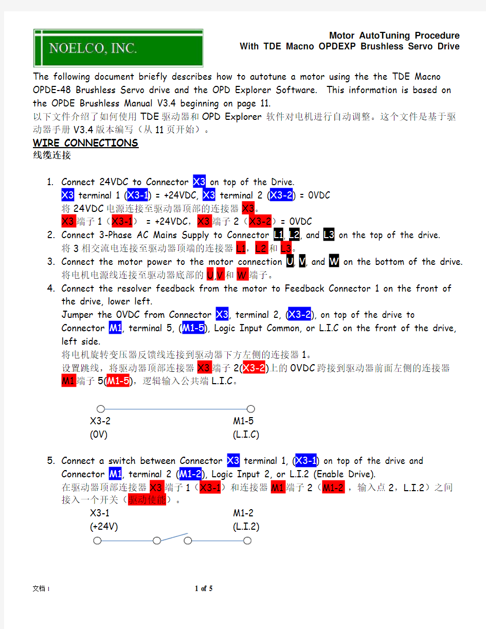
1.Connect 24VDC to Connector X3 on top of the Drive.
X3 terminal 1 (X3-1) = +24VDC, X3 terminal 2 (X3-2) = 0VDC
将24VDC电源连接至驱动器顶部的连接器X3。
X3端子1(X3-1) = +24VDC,X3端子2(X3-2)= 0VDC
2.Connect 3-Phase AC Mains Supply to Connector L1, L2, and L3 on the top of the drive.
将3相交流电连接至驱动器顶端的连接器L1,L2和L3。
3.Connect the motor power to the motor connection U, V, and W on the bottom of the drive.
将电机电源线连接至驱动器底部的U,V和W端子。
4.Connect the resolver feedback from the motor to Feedback Connector 1 on the front of
the drive, lower left.
Jumper the 0VDC from Connector X3, terminal 2, (X3-2), on top of the drive to
Connector M1, terminal 5, (M1-5), Logic Input Common, or L.I.C on the front of the drive, left side.
将电机旋转变压器反馈线连接到驱动器下方左侧的连接器1。
设置跳线,将驱动器顶部连接器X3端子2(X3-2)上的0VDC跨接到驱动器前面左侧的连接器
M1端子5(M1-5),逻辑输入公共端L.I.C。
X3-2 M1-5
(0V) (L.I.C)
5.Connect a switch between Connector X3 terminal 1, (X3-1) on top of the drive and
Connector M1, terminal 2 (M1-2), Logic Input 2, or L.I.2 (Enable Drive).
在驱动器顶部连接器X3端子1(X3-1)和连接器M1端子2(M1-2 ,输入点2,L.I.2)之间接入一个开关(驱动使能)。
X3-1 M1-2
(+24V) (L.I.2)
ENTER MOTOR DATA
输入电机参数
Collect the following motor data and enter into the drive Parameters using OPDExplorer: 收集以下电机参数并用OPDExplorer软件将参数输入到驱动器参数中:
1.Rated motor current in amps (A)
电机额定电流(A)
1.1.Calculate the motor current as a percentage (%) of the drive current.
Motor Current (A) / Drive Current (A) * 100 = Rated Motor Current %
计算电机额定电流占驱动器电流的百分比。
电机电流(A)/驱动器电流(A)*100 = 电机额定电流%
1.2.Enter this value in Parameter P61
将数值写入参数P61。
2.Rated motor Voltage, or BEMF (Back-EMF).
电机额定电压
2.1.Enter this value in Parameter P62
将数值写入参数P62。
3.Rated motor speed (nominal) in RPM
电机额定转速
3.1.Enter this value in Parameter P63
将数值写入参数P63。
4.Maximum motor operating speed in RPM
电机最大运行速度
4.1.Enter this value in Parameter P65
将数值写入参数P65。
5.Number of motor poles
电机的极数
5.1.Enter this value in Parameter P67
将数值写入参数P67。
6.Number of resolver poles
旋转变压器极数
6.1.This value is normally 2. Enter this value in Parameter P68
将数值写入参数P68(通常为2)。
ENTER MAINS VOLTAGE
输入电源电压
Enter the Mains supply voltage in Parameter P87.
将主电源电压值输入到参数P87。
VERIFY SENSOR DATA
检查传感器数据
The sensor information is in reference to the feedback sensor in the drive. This is typically Resolver or Resolver DDC (Hi-resolution resolver). This value is stored in Connection C00. Resolver = 4, Resolver DDC = 5.
传感器信息参考驱动器反馈传感器。这通常为旋转变压器或高分辨率旋转变压器(DDC)。传感器数
值存储在参数C00,旋转变压器 = 4,高分辨率旋转变压器 = 5。
ENABLE USING NEW MOTOR & SENSOR DATA
使用新电机和传感器数据
In OPDExplorer, go to Connection C75, enter the value 1. This will tell the drive to use the new data that was entered above for the auto tuning tests. If C75 = 0, the drive will use its Default Values for the test instead of the values entered above.
在OPDExplorer软件中,找到参数C75,输入数值1。这将让驱动器使用以上输入的新的数值进行自动调整测试。如果参数C75=0,驱动器将使用默认的数值进行测试而非以上输入的数值。
TEST PROCEDURES
测试过程
1.The motor MUST be disconnected from the mechanical load.
必须断开电机的机械负载。
2.Make sure the Enable Switch is Open.
确认使能开关是打开的。
3.Apply the 24VDC power.
接入24VDC电源。
4.Apply the 3-phase AC mains power.
接入3相交流电源。
5.Connect your PC to the OPDE drive with the communications cable
将电脑用通讯电缆连接至驱动器。
Sensor Test
传感器测试
For the Sensor test, also refer to the OPDEXP Brushless User’s Manual, page s 11-22.
对于传感器测试,可参考驱动器用户手册,11-22页。
6.In OPD Explorer, go to Connection C41, enter the value 1.
在OPD Explorer中,找到参数C41,输入数值1。
7.The drive display will read –C - - -
驱动器显示屏将显示C - - -。
8.Close the switch to Enable the drive.
闭合开关使能驱动器。
9.The drive display will read –C r u n
驱动器显示屏将显示C run。
10.The motor will rotate at least 2 revolutions during the test.
在测试过程中电机会至少旋转2圈。
11.If the test ends with success, the drive display will read - C En d
如果测试成功,驱动器显示屏将显示C End。
12.Open the switch to Disable the drive.
打开驱动器使能开关。
13.In OPD Explorer, go to Connection C41, enter the value 0.
在OPD Explorer中,找到参数C41,输入数值0。
14.If the test is not successful, the drive will display an alarm
如果测试未成功,驱动器会显示报警。
14.1. A.E.0.H–Alarm A14.0 – Motor Phase Inverted
During autotuning, it was detected that the motor phases are not phased properly with the feedback.
Corrective Action: Swap 2 phases and repeat the test.
A.E.0.H–报警A14.0 –电机相位倒置。
在自整定过程中,驱动器检测电机相位与反馈是否合理匹配。
解决措施:交换任意两相,重复测试。
14.2. A.E.1.H– Alarm 14.1 – Motor not connected
Duringautotuning, it was detected that the drive and motor are not connected properly.
Corrective Action: Check the drive and motor connections and repeat the test.
A.E.1.H–报警A14.1 –电机未连接。
在自整定过程中,驱动器检测驱动器和电机是否连接合理。
解决措施:检查驱动器和电机连接线,并重复测试。
14.3. A.F.3.H– Alarm 15.3 – Wrong sensor poles or motor poles
Duringautotuning, it was detected that the number of poles entered for the motor or
sensor do not match the device.
Corrective Action: Check the values in P67&P68 and make sure they match the motor and resolver number of poles. Repeat the test.
A.F.3.H–报警A15.3 –传感器极数或者电机极数错误。
在自整定过程中,驱动器检测输入的电机极数或传感器极数是否与设备匹配。
解决措施:检查参数P67&P68,确保其数值与电机极数和传感器极数一致,并重复测试。
Auto-Tuning Test
自动调整测试
For the Auto-Tuning test, also refer to the OPDEXP Brushless User’s Manual, page s 23-28. 对于自动调整,可参考驱动器手册,23-28页。
15.In OPD Explorer, go to Connection C42, enter the value 1.
在OPD Explorer中,找到参数C42,输入数值1。
16.The drive display will read –A - - -
驱动器屏幕显示–A - - -
17.Close the switch to Enable the drive.
闭合驱动器使能开关。
18.The drive display will read –A r u n
驱动器屏幕显示–A r u n
19.The motor will rotate at least 2 revolutions during the test.
在测试过程中电机会至少旋转2圈。
20.I f the test ends with success, the drive display will read –A En d
如果测试成功,驱动器屏幕显示- A En d
21.Open the switch to Disable the drive.
打开驱动器使能开关。
22.I n OPD Explorer, go to Connection C42, enter the value 0.
在OPD Explorer中,找到参数C42,输入数值0。
23.S AVE the Parameters to EEPROM by setting Connection C63 = 1.
设置参数C63=1将参数保存至EEPROM中。