奥迪A4车辆电子控制单元J519
Service
Audi A4
Electrical system
Vehicle electrical system control unit (J 519)
Contents:
General function description Page 3
Light control Page 5
Light monitoring Page 7
Turn signal / hazard light control Page 9
Brake light control Page 10
Activation relay Page 11
Wiper / wash control Page 11
SG for trailer recognition Page 13
Emergency operation Page 15
Fault finding Page 16
Diagnosis Page 17
The trainer information is structured for the
self study programme 254 – Audi A4 2001
is not a
workshop manual.
For maintenance and repair operation
please use the current
technical literature.
General function description
Vehicle electrical system control unit
By using a vehicle electrical system control unit,
the vehicle weight could be reduced due to less
cable and a lower number of relays and control
units.
The functions
- Wiper activation
- Drive light activation with lamp control
- Horn activation
- Load-reduction relay activation
- Turn signal and hazard light activation
- Brake light activation
are taken over by the vehicle electrical system
control unit as a central unit.
Signal transmission is via the CAN bus
convenience with a speed of 100 kBaud.
There is an active data exchange between
- Steering column electronics in switch module
- Dash panel insert (with Gateway to the CAN
bus drive)
- Steering wheel electronics module
- Central convenience electronics (CCE) with
the relevant door modules
- Control unit for trailer recognition
- Vehicle electrical system control unit
- Multi-function control unit for special vehicles
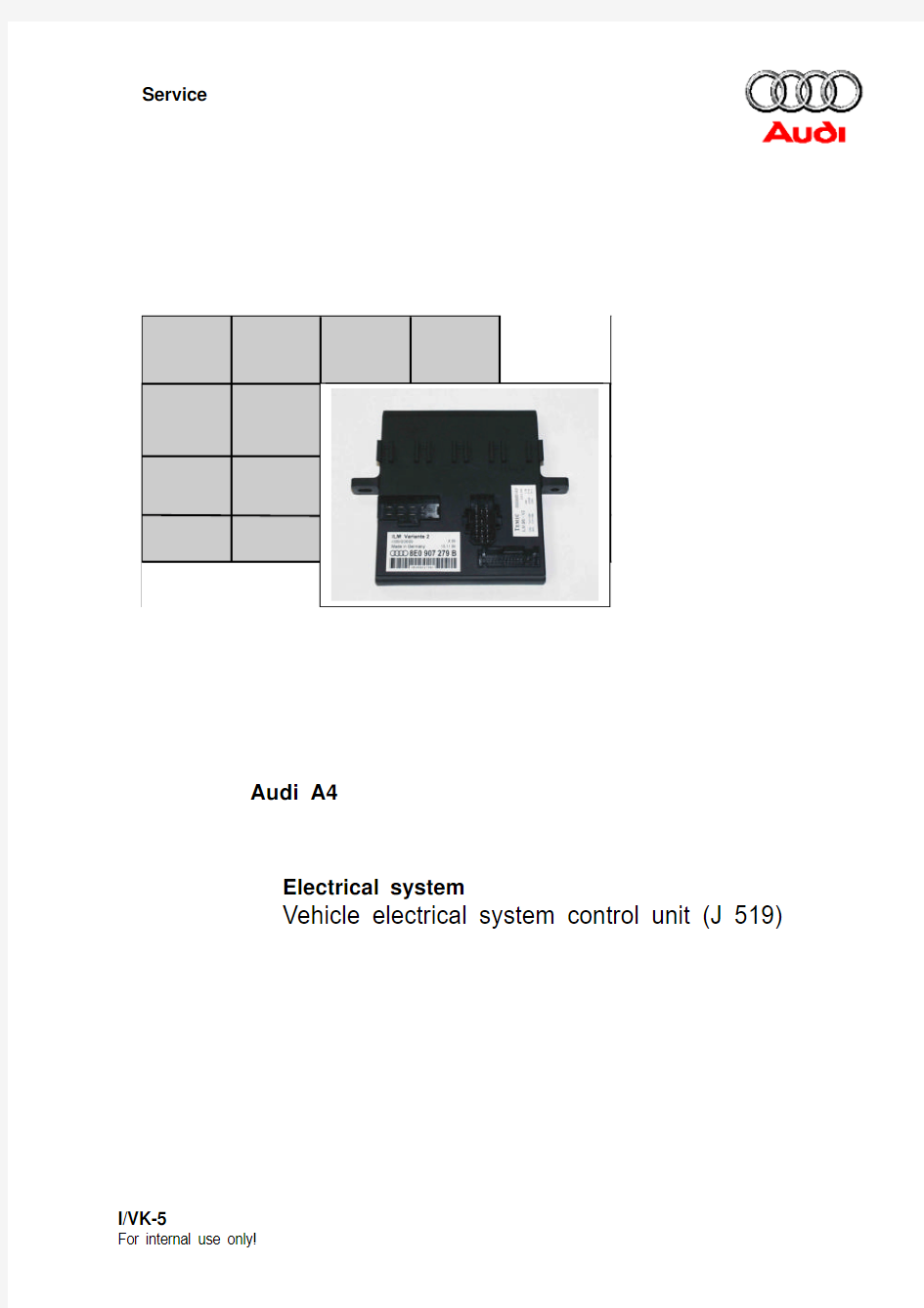
Control unit versions
Low-line for standard equipment
8E0 907 279 (C)
Low-line for vehicle with headlight
washer system
8E0 907 279 A (D)
High-line for vehicle with DIS
(driver information system)
8E0 907 279 B (E) Gateway
Passenger
door module
Driver door
door module
Rear
door module
Air
conditioner
Trailer recog-
nition CU
Additional
heater
Tyre pressure
check system
Parking aid
Multi-function
control unit
Steering
column
electronics
Vehicle
electrical
system
control unit
Gateway
Driver seat
memory
Active data
exchange
Steering
wheel
electronics
Fitting location:
Front left footwell below dash panel cross member – instead of the earlier central electrics
Country versions
Depending on country, various regulations apply for the vehicle lighting system.
The various light activations are stored in the EEPROM and can be adapted to the relevant specific regulations via the coding.
Vehicles that are exported into these countries are generally equipped with the high-line version even if a driver information system is not fitted.
Activated components
In the low-line version, the following functions are performed by the vehicle electrical system control unit:
- Hazard light system
- Turn signal
- Window wiper
- Washer pump incl. rear wiper activation in Avant
- Activation of horn and load-reduction relay
- HWS (headlight washer system)
- Parking light, right *
- Parking light, left *
- Main beams, right
- Main beams, left
- Turn signal, right **
- Turn signal, left **
- Number plate lamps
* front and rear are activated together
** front, rear and side are activated together
In the high-line version the lighting elements are activated individually, including those marked with * and ** in the low-line version.
The following lighting units are activated additionally via the processor:- Dipped beam headlights, left,- Dipped beam headlights, right,- Fog light, left,- Fog light, right,- Brake lights, left, centre and right,- Reversing light, left,- Reversing light, right,- Rear fog light.
Voltage supply Normal operation min. U batt = 9 V max. U batt = 15 Volt
An increased supply voltage of up to 6 Volt is permitted for the horn, turn signal activation and wiper washer system with HWS functions.
Light control
Rear light
High-line
In vehicles with driver information system, the brake light filament in the 2-filament bulb is used as the rear light. For this purpose, the 21 watt
lamp is activated via a PWM signal to minimise the lighting power. Thus, both rear lights are capable of diagnosis without additional semiconductor elements and wiring.
A defective 2-filament lamp is indicated by the failure of the 21 watt brake light filament.In the low-line version the contact for the 5 watt glow filament is present and activated.
Brake actuated
Side light ON
Encodeable daylight driving lights
The coding for the relevant country can be found in the coding table in chapter “Diagnosis”.Example: In vehicles destined for Denmark,Finland, Norway and Sweden with daylight
driving lights without Xenon headlights, the dipped beam headlights and sidelights are dimmed to 92%.
When dipped beam headlights are switched on,the full lighting output is available.
Headlight range control
The headlight range control is dynamic and is activated by a separate control unit. The control unit is activated by a conventional connection to the rotary light control (terminal 56b.)Reversing light activation Low-line
With conventional wiring via the reverse gear switch or the multi-function switch with multitronic/automatic gearbox.
High-line
For the reversing light activation, the signals are transmitted to the vehicle electrical system control unit via the convenience CAN bus from the central convenience electronics. There, the direct input from the reverse gear switch or multi-function switch is available.
Daylight driving
lights
Dipped beam
Light switch
Light monitoring
The light monitoring differentiates between the test types cold and warm monitoring.Function
With ignition ON, the lamp circuit is activated 5 times for 200μsec in a cycle of 200 msec.In electrical consumers with an output >50 watt, this is recognised via an current detection in the semiconductor element.
For the other electrical consumers, only an open or closed circuit is detected.
Cold monitoring During cold monitoring, a test current is applied to
the relevant lighting circuit, each time the ignition
is switched ON. This test current is checked via a current threshold measurement or status test (circuit open/closed). This means that individual lamps can be recognised as defective even before initial operation.
Warm monitoring
If a lamp fails after cold monitoring was OK, a fault is only displayed or stored after this lighting circuit has been switched on.
Important:
This is only intended an illustration of the circuit test.
Open circuit cannot be detected by means of a voltage measurement.
High-line
The current value thresholds are:
For the low line version, these lighting circuits can be conventionally activated via the rotary light control.
For Xenon headlights, cold monitoring cannot be performed due to the ignition control unit.The third brake light and number plate lamp can only be
detected in the case of complete failure, as the lighting components are connected in parallel.If a fault is detected, the fault is stored in the vehicle electrical system control unit.
High-line with driver information system
The defective lamp is accurately defined in the driver information display, e.g. dipped beam
headlights front left, in conjunction with the yellow warning symbol “lamp defective”.
M o n i t o r i n g
D i p p e d b e a m
M a i n b e a m
F o g l i g h t
Cold 3.7 A 2.0 A 2.0 A Warm 2.0 A 1.0 A 2.0 A
Turn signal and hazard light activation
Functions
- Turn signal flashing - Motorway flashing
- Hazard warning flashing - Crash flashing - ATWS flashing
- CL flashing when opening/closing
- Key learn flashing for radio key adaption - Panic flashing (USA)-
Taxi alarm flashing
Turn signal flashing
If a side or trailer turn signal lamp fails, the turn signal frequency is not influenced.
Motorway flashing
If the turn signal switch is actuated for <1 sec. the turn signal function is activated for 3 flashing cycles.
Hazard warning flashing
There are 2 operating modes: Sequence
flashing via terminal 15 – normal flash in light/dark ratio of 55 to 45.
Flashing via terminal 30 – slow flash in ratio of 35
to 65 to minimise the current consumption with ignition OFF.
A “stuck” hazard warning switch is detected by the self-diagnosis after 30 seconds and stored in the
fault memory.
With terminal 30
With terminal 15
The locating light of the hazard warning switch is only switched off when the CAN convenience bus switches to sleep mode.
The functions - ATWS flashing
(anti-theft warning system)- CL flashing when opening/closing - Key learn flashing for radio key adaption - Crash flashing - Panic flashing (USA only)
are specified by the central convenience
electronics (CCE) and transmitted via the CAN convenience bus.
Taxi alarm flashing
Taxi alarm flashing is activated by an independent multi-function control unit which is connected to the convenience bus.
The turn signal clicking is generated by an integral acoustic relay in the dash panel insert and can only be heard during turn signal flashing.
Brake light activation
High-line
The brake light activation is connected from
terminal 30 via the brake light switch to the control unit
for the vehicle electrical system. The brake pedal switch is used as a redundant safety switch.
Low-line
The brake light activation is effected via
conventionally fused wiring via the brake light switch.
High-Line
Activation relay
The activation for the external horn and load-
reduction relay is effected directly by the vehicle
electrical system control unit. The switch-on
commands are transmitted from the relevant
switch, via the convenience CAN bus from the
steering column switch module.
the HWS relay are now integrated into the vehicle
electrical system control unit and are controlled by
the microprocessor.
Wiper/wash functions
?Flick wiping Array?Interval wiping – speed dependent in
4 stages
?Stage 1
?Stage 2
?Washing – depending on actuating time of
wiper switch (pull) the following cycles are
activated
Actuating time Wiper cycles
1 x < 500 ms1
1 x > 500 ms2
2 x < 500 ms2
?Re-wiping
5 seconds after completion of wiper/wash function,
automatic re-wiping in stage 1 is performed
Blocking detection
Blocking detection is intended to protect the wiper motor.
With switch in ON position,
?if a current > 32 A is detected, the wiper motor switches off immediately
or
?if no level change occurs at terminal 31b (cam contact) within 4 seconds, the system
switches off. Renewed activation for 4
seconds in stage 1 is effected after a pause
of 12 seconds. This procedure is repeated
cyclically until the wiper switch is set to OFF. With switch in OFF position,
?if after ignition ON it is recognised that
terminal 31b (cam contact) is not in rest
position, the wiper motor is activated in stage
1 (max. 4 seconds) until the rest position is
recognised via terminal 31b. This procedure
is activated only once within an ignition ON
phase.
Headlight washer system (HWS)
The activation of HWS is via an internal relay, with an activation period of 800 ms per wiper cycle
when
- the dipped beam headlights are switched on,
- the windscreen washer is active and
- the wash water level is OK.
The HWS is switched on with a delay of 900 ms if
all conditions are met after the front washing.
The function link with the wash water level warning in the check system is intended to save water, so that the window washer function remains functional even if the level is low. Additionally, this is a protection feature for the HWS pump in order to avoid the shortening of the service life by running dry.
Control unit for trailer recognition J345
For operation with trailer, a control unit for trailer recognition J345 is required, which can evaluate the CAN convenience messages for the vehicle lighting and transmit them to the power outputs.
Trailer recognition
The trailer recognition is performed every 10ms through a continuous, cyclical powering of the - left turn signal and/or the brake light, with
ignition ON.or - with ignition OFF via the brake light.
If one of the two power circuits is OK, trailer operation is recognised by the control unit.
.
Important : Illustration only valid for
Blinklicht links
If the vehicle is parked with the trailer connected (ignition OFF), the trailer recognition is continued.
Lamp failure can only be detected if the relevant circuit is open.
If, for example, the brake light lamp has failed, the control unit cannot detect the failure due to the parallel activation of two light components.High-line
An open trailer circuit is displayed in the driver information system as, for example, “Trailer turn signal, left” together with the yellow warning symbol for the lamp defect.
The power output stages in the control unit for trailer recognition are designed for maximum power as follows:
Side light, left 10 x 5W Side light, right 10 x 5W Turn signal, left 2 x 21W Turn signal, right 2 x 21W Brake light 4 x 21W Rear fog light 2 x 21W
Reversing light 2 x 21W The above-mentioned values are maximum
values. If these values are exceeded, a fault is set or indicated due the increased current consumption.
Ignition off
and CAN bus convenience active
Ignition off
and CAN bus convenience in sleep mode
Important : Illustration valid for open turn signal circuits (left side)
The trailer recognition control unit is only able to
perform self-diagnosis indirectly.
In case of faults only a defective trailer recognition
control unit is recognised and is stored in the fault
memory as “01517 – CONTROL UNIT FOR
TRAILER RECOGNITION DEFECTIVE”.
If a trailer coupling is retrofitted, it is imperative
that a trailer recognition control unit is installed at
the intended positions, as the socket wiring cannot
be connected directly to the output wiring. Fault
detection would occur due to increased current
consumption in the vehicle electrical system
control unit.
Emergency operation of trailer recognition control unit
If the CAN bus (high and low line) is interrupted,
both rear lights are activated via a safety circuit. Emergency operation of vehicle electrical system control unit
If the processor fails the
- dipped beam headlights (high line only) and
- side light
are maintained via a redundant signal path.
If an undefined fault is present in the rotary light
control, the side light and dipped beam headlights
switch on automatically after approx. 2 seconds.
The brake light function is also ensured via an
emergency circuit.
Fault finding
High-line
During fault finding, difficulties may be
encountered as the various power circuits are activated differently.
In certain circuits, the voltage measurement in an open line, defective bulbs or similar cannot be performed.
This applies to the following circuits:- Rear light -
Front side light -
Reversing lights -
Rear fog light
Side light
Reversing light
Rear fog light
Rear light
Diagnosis
Address word
The address word for the vehicle electrical system
control unit is 09 – electronic central electrics or
under vehicle electrical system (high/low-line).
Entry into fault memory (02)
If the fault
is displayed, an adaption of the vehicle
electrical system control unit to the vehicle
must be performed.
Refer to “Adaption”
Final control diagnosis (03)
Coding (07)
Not assigned 0
Light sensor *
0= without light sensor 1= with light sensor
X Trailer coupling
0= without TC 1= with TC
X Headlight system *
0= Halogen headlights 1= Xenon headlights
X Country equipment *
1= Rest of the world
2= Rest of the world –northern countries 3= USA 4= Canada 5=Denmark
6=Special vehicles
X
* only codeable for high-line
Actuator
Low/ High
Turn signal, left X X Turn signal, right X X Hazard warning light X X Side light, left X X Side light, right X X Rear light, left X X Rear light, right X X Main beam, left X X Main beam, right X X Number plate light X X Wiper, stage 1X X Wiper, stage 2
X X Rear screen wiper motor X X Washer pump, front X X Washer pump, rear
X X Windscreen washer pump X X Relay activation, horn X
X Dipped beam, left X Dipped beam, right X Fog light, left X Fog light, right
X Reversing light, left X Reversing light, right
X Brake lights (left, right, centre)X Rear fog light
X
Measured value blocks (08)
A chassis number is stored in channel 81 and is
used for the anti-theft security.
Please observe the procedure as described in
“Adaption”.
OUTPUT SIGNALS
001Voltage supply Horn Terminal 75HWS
on Off on
Off
on
Off
002Turn signal
Front left Turn signal
Rear left
Turn signal
Front right
Turn signal
Rear right
on off on
off
on
off
on
off
003side light
Front left Side light
Rear left
Side light
Front right
Side light
Rear right
on off on
off
on
off
on
off
004Main beam
left Main beam
right
Number plate light Function display
Hazard warning
lights
on off on
off
on
off
on
off
005Wiper
front Washer
front
Wiper
rear
Washer
rear
off Stage 1 Stage 2on
off
on
off
on
off
INPUT SIGNALS
006Rotary light control Hazard warning
switch sensor
Terminal 75Cam contact
off
Stage 1 (side light) Stage 2 (dipped beams) Stage 3 (not assigned) Stage 4 (fog light)
Stage 5 (RFL)
actuated
not actuated
on
off
on
off
大众奥迪所有控制单元编码
大众控制单元编码------强烈推荐给大家!! C5 发动机 4D0 907 551 AH CODING 号码 01 - engine 发动机系统 4d0 907 551 ah 2.8l v6/5v motr hs d04 coding: 06201 wsc 06335 tdc 16825 - evap emission control sys: incorrect flow Re:大众奥迪全车系 audi a4 1.8 08 -空调系统 4a0 820 043d coding 00040 00060 Re:大众奥迪全车系电脑版本号大家都来贴!!! 宝来汽车电脑版本号 01- 发动机:06a 906 032jb 1.6l 5v at ag4 4629 coding:00033 wsc:00000 02-自动变速箱 零件号码01m 927 733 kk 组件ag4 getriebe 01m 4989 coding 号00000 维修站号码00000 17-组合仪表(防盗) 电脑版本:1j5920806c komb1+wegfahrsp vdo v02 coding: 01102 wsc: 00000 46-舒适系统 零件号码 1c0 959 799 组件1m komfortger athlo 0002 coding 号00259 维修站号码00000 2003-8-15 0:01:11 以上为宝来1.8T AT车全车电脑版本号 ecu 外观照片 01 - 发动机 02 - 自动波 03 - abs mk60 15 - airbag 17 - 仪表/immo 19 - can-bus 网关 19 - 网关 斯科达法比亚 AIRBAG 1J0 909 603 vag number index coding =========== ===== ===== 1j0 909 603 as airbag 16723 1j0 909 603 at airbag 16724 2002 Jetta 1.8T 电脑版本号 2002 jetta 1.8t 金德 k81/pc2000 for windows xp 双模式 01 --发动机 : 06a 906 032 hf 1.8l r4/5vt g 0004 coding: 07550 wsc 13622 vin:3vwse69m62m112530 immo sn:vwz7z0a4185284 02 -- 自动波 09a 927 750 t ag5 getriebe 09a 0193 03 -- abs: 1c0 907 379 k asr front mk60 0103
上海大众朗逸轿车车身控制单元电路分析及故障排除00
朗逸2.0自动挡无法启动 BCM损坏致整车瘫痪 2010-8-24 14:19| 来自: 汽车驾驶与维修|原作者: 陈中泽| 查看数: 292| 评 论数: 0 故障现象:一辆2008年生产的朗逸2.0 L自动挡轿车,行驶里程4.3万 km,用户反映,发动机无法起动。维修人员赶到现场检查,发现点火开关处于起动位置时起动机不能转动,发动机无法起动,于是将车拖回维修站。 检查分析:维修人员进行基本检查发现,除用户描述的现象外,转向灯、危急闪烁报警灯、制动灯、倒车灯、刮水器、喇叭、电动车窗、室内灯和中控锁功能均已失效。用遥控器或点火钥匙都不能使车门闭锁/解锁,按下空调操作单元上的按键和转动鼓风机速度调节旋钮,均无反应。 如此多个车身电器同时出现故障,应与BCM有关。连接VAS5052故障诊断仪,点击自诊断功能打开网关列表,控制单元列表中显示发动机控制单元与BCM均存在故障。发动机控制单元故障码是:01320——与HVAC(空调)控制单元失去通信,当前存在。BCM故障码有9个,分别是:03435——车内灯/停车灯端子30断路,当前存在;00329——后行李舱盖解锁启动对地短路,当前存在;03396——中控锁供电端子30断路,当前存在;00920——驾驶员侧及乘客侧加热后视镜断路,当前存在;03580——加热式车外后视镜端子断路,当前存在;03585——挡风玻璃雨刮器端子30断路,当前存在;03444——起动机点火开关不可靠信号,
偶发;03591——喇叭启动断路,当前存在;03592——喇叭端子30断路,当前存在。点击环境条件按钮查看控制单元,识别到每个故障记忆时的里程,这些故障码为同时发生。 将故障码复制到U盘保存,删除故障记忆。检测仪屏幕左上方出现文本提示如下:功能取消不满足要求。点击输出诊断测试模式(DTM)功能选项,对转向灯、刮水、喇叭进行功能测试,屏幕左上方再次出现功能取消不满足要求的文本提示。点击测量值功能,查阅001组的测量值为关(点火开关D/86s端子信号)、关(D/50端子信号)、开(D/75端子信号)、关(D/15端子信号)。点火开关处于ON的位置时正常值应为开、关、开、开。查阅040组、041组对J519的8个30号线供电端子的测量值,依次为正常(转向灯/制动灯)、异常(内部灯)、异常(前风窗刮水)、正常(后风窗加热)、异常(外后视镜)、异常(喇叭信号)、正常(倒车灯)和异常(中央集控)。检查对BCM供电异常的熔丝S18、S19、S49和S50,4个熔丝均正常。用引导性功能进入BCM数据块选项,点击上述各项测量值列表如(图16),此时发现对BCM供电的8个30端子状态均为正常,但86s和15号线依旧异常。 测量值003组是刮水开关E22和间歇刮水调节器E38的测量值,分别将E22与E38置于不同的挡位,测量值由未操作变为接通,间歇刮水调节器的测量值显示1-4级的变化,但刮水电机没有响应(图17)。012组1区和3区是左前电动窗开关E40和右前电动窗开关E81的信号测量值,按动开关,有输入信号显示,但电动窗不动作,这些都表明BCM虽然接收到了开关信号却无输出指令。005组是4个车门开关的测量值,均显示关闭,依次开启各车门,显示无变化。007组显示4个车门闭锁/开锁的实时状态。查看4个车门,均处于开锁状态,但4个区域的测量值显示:解锁、锁止、解锁、锁止。依次按动门提,测量值不变化,
大众汽车电脑编码大全
大众电脑编码大全 奥迪A6 2.8L 01)3B0 907 551 BF 2.8L V6/5V G01 001 CODING:04552 02)4B0 927 156 AJ AG5 01V 2.8L5V USA 3132 CODING:00004 03)3B0 614 111 ABS/ASR 5.3 FRONT D00 CODING:00031 15)4B0 959 655 G Airbag Fronttseite 2001 CODING:00004 35)4B0 962 258 J Central Lock/Alarm D35 CODING:06731 45?)4B0 907 357 LEDCHTWETTEREGLER D004 CODING:00005 36)4B0 959 608 Sitzmamnory R1 F 000 CODING:00000 56)4C0 035 186 Radio D02 CODING:00207 66)4B0 919 283 ParkingSystem A6 Row D18 CODING:01106 17)4C0 920 930 A Ch-kOMRIINSTR VDO D12 CODING:00162 08)4B0 820 043 AF A6-Klimavnllautomat D65 coding:00160 奥迪A6 2.4L VIN:VBA24B013014521 ?15??01)3B0 907 552 AD 2.4L V6/5V G 0000 CODING:04552 02)4B0 927 156 AL AG5 01V 2.4L5V RHW 2526 CODING:00013 03)3B0 614 111 ABS/ASR 5.3 FRONT D00 CODING:00031 15)4B0 959 655G Airbag Fronttseite 2000 CODING:00004 35)4B0 962 258 E Zentralverrieg.DWA D34 CODING:04683 45)4B0 951 178 A (?Unnenmumueberw) D04 CODING: 00001 36)4B0 959 760 A Sitzmemnry D0556)4C0 035 186 Radio D02 CODING:00207 66)4B0 919 283 Parkingsystem A6 ROW D18 CODING:00106 17)4C0 920 930 A C5-KOMHI INSTR VDO D09 CODING:00062 08)4B0 820 043 AF A6-Klimavcllautomat D65 CIDING:00160 大众奥迪1.8L 01)4R0 906 018 CA 1.8L R4/5VT 0003 CODING:04502 03)3B0 614 111 ABS/ASR 5.3 FRONT D00 CODING:00022 15)4B0 959 655G Airbag Frongt+Seite 2001 CODING:00004 35)4B0 962 258J Central lock/Alarm D35 CODING:00001 56)4C0 035 186 Radio CODING:00201 17)4C0 920 900A C5-KOMRI INSTR VDO D12 CODING:00144 08)4B0 820 043H A6-Klimauollautomat D64 CODING:00140 宝来 1.8L 01)06A 906 032 LD 1.8L R4/5VT 0001 CODING:04530 02)01M 927 733 LL AG4 Getribe 01M 4956 coding:00000 03)1c0 907 379K ASR PRONT MK60 0103 CODING:0021505
汽车发动机电子控制单元(ECU)
汽车发动机电子控制单元(ECU) 功能说明书
佛山菱电变频实业有限公司王和平 2004年3月 一、概述 汽车发动机控制系统一般有进气系统、燃油供给系统、点火系统、电脑控制系统四大部分组成。进气系统由空气滤清器、空气流量计、节气门、进气总管、进气歧管等组成,它为发动机可燃混合气提供所需空气;燃油供给系统由燃油泵、燃油滤清器、燃油压力调节器、喷油器和供油管等组成,它为发动机可燃混合气提供所需燃油;点火系统为发动机提供电火花,它由点火电子组件、点火线圈、火花塞、高压导线等组成;电脑控制系统由电子控制单元(ECU)和各种传感器组成,它控制燃油喷射时间和喷射量以及点火时刻。 汽车发动机电子控制单元(ECU)是汽车发动机控制系统的核心,它可以根据发动机的不同工况,向发动机提供最佳空燃比的混合气和最佳点火时间,使发动机始终处在最佳工作状态,发动机的性能(动力性、经济型、排放性)达到最佳。 汽车发动机机电子控制单元(ECU)的主要功能: 1、燃油喷射(EFI)控制 ⑴、喷油量控制
发动机控制器(ECU)将进气量和发动机负荷作为主要控制信号,以确定喷油脉冲宽度(即基本喷油量),并根据循环水温度、进气温度、进气压力、尾气氧含量等信号修正喷油量,最后确定总喷油量。 ⑵、喷油正时控制 采用多点顺序燃油喷射系统的发动机,ECU除了控制喷油量外,还要根据发动机各 缸的点火顺序,将喷油时间控制在最佳时刻,以使燃油充分燃烧。 ⑶、断油控制 减速断油控制:汽车在正常行驶中,驾驶员突然松开油门踏板时,ECU自动中断燃油喷射,直至发动机转速下降到设定的低转速时再恢复喷油。 超速断油控制:当发动机转速超过安全转速或汽车车速超过设定的最高车速时,ECU自动中断喷油,直至发动机转速低于安全转速一定值且车速低于最高车速一定值时恢复喷油。 ⑷、燃油泵控制 当打开点火开关后,ECU控制燃油泵工作3秒钟,用于建立必要的油压。若此时发动机不起动,ECU控制燃油泵停止工作。在发动机起动和运转过程中,ECU控制燃油泵正常运转。 2、点火(ESA)控制 ⑴、点火提前角控制 发动机运转时,ECU根据发动机的转速和负荷信号,计算相应工况下的点火提前角,并根据发动机的水温、进气温度、节气门位置、爆震信号等修正点火提前角,最
大众汽车控制模块编号
大众汽车控制模块继电器编号 1# 进气预热继电器 4# 安全带报警系统控制单元 007# 组合继电器 10# 怠速及超速切断控制单元811 919 096(零件号) 13# 空调继电器 15# 雾灯继电器 17.18# 卸荷继电器 19# 刮水继电器 21# 闪光器 22# 挂车遇险报警器 24# 车窗玻璃升降继电器 29# 安全带报警系统控制单元 30# 电控单元继电器 31# 散热器风扇继电器 32# 电控单元继电器 33# 前灯清洗系统继电器 38# 冷却水泵继电器.乘客室通风系统 41# 触媒警示继电器 42# 冷却液不足指示继电器 42A# 冷却液不足指示继电器 44# 催化反映器报警控制单元 47# 自动预热过程控制继电器 51# 喇叭继电器 53# 喇叭继电器 60# 预热塞继电器 61# 超速切断控制单元继电器 67# 油泵继电器 72# 后窗刮水器和洗涤器继电器 78# ABS液压泵继电器 79# ABS继电器 80# 进气预热继电器 80# 汽油泵继电器(大众面包车) 82# 怠速控制提升控制单元 83# 电动坐椅自由轮锁止机构继电器 85# ABS液压泵继电器.ABS电磁阀继电器 87# ABS锁定控制继电器 91# 燃油泵启动控制单元 94# 暖风.A/C继电器 99# 可调整时间间歇/喷水继电器 100# 二次空气泵继电器 102.104# 预热塞继电器 111# 二次空气辅助泵控制继电器
114# 暖风.蒸发器继电器 125.155# 怠速提升继电器 126# 启动锁止继电器 137# 预热塞系统和EGR.CAT柴油发动机的控制器140# 空调继电器(大众面包车) 147# 压缩机切断继电器 150# 启动锁止.倒车灯继电器 151# 后雾灯继电器.挂车牵引继电器 167# 燃油泵继电器 175# 启动锁止.倒车灯继电器 186# 启动机锁止继电器(防盗报警系统,PASSAT) 208# 油泵继电器 212# 燃油泵继电器(4缸红旗) 213# 卸荷继电器 214# 风扇继电器 215# 燃油泵继电器(5缸奥迪) 216# 启动预热继电器 262# 怠速控制单元 263# 油泵继电器 271# 刮水继电器(5缸奥迪) 272# 散热器风扇控制继电器(5缸奥迪) 285# 电动车窗升降控制单元 296# 空调继电器 309# 油压报警器 316# 舒适控制单元 317# 刮水/洗涤器间歇继电器 363# 电动玻璃升降控制单元 370# 散热器风扇继电器.二次空气继电器 377# 刮水间歇继电器 398# 空调切断继电器 404# 燃料预供应继电器 411# 中控锁继电器 412# 点火线圈供电 428# 发动机控制单元供电(宝来1.8T) 431# 中央门锁控制器 449# 踏步灯继电器 453# 刮水间歇继电器(奥迪100) J1 ——闪光继电器21# J2 ——危险闪光继电器 J4 ——喇叭继电器 J5 ——雾灯继电器 J6 ——稳压器(仪表内部JEEDA) J8 ——停车加热继电器
大众汽车安全气囊编码方法
大众汽车安全气囊索引码与编码 更换完安全气囊控制单元后编码是多少?我们可以在线编码、利用旧的编码。如果旧的编码没有记录或者旧的编码无法读取。怎么编码?还可以利用索引码进行编码。 先来看看索引码怎么查。一:外包装盒(不要乱扔)二:配件库查询。 S03就是包装盒上的索引码(忽略S)。知道这 个后,下面要按照表格来查询编码。按照表格, 这个安全气囊的编码为12339。 大众车用安全气囊控制单元编码快速查询表 配件索引号SRS ECU 编码 配件索 引号 SRS ECU 编码 配件索 引号 SRS ECU 编码 配件索 引号 SRS ECU 编码 A 00065 0Z 12378 22 12850 3G 13127 C 00067 11 12593 24 12852 3J 13130 01 12337 12 12594 25 12853 3K 13131 02 12338 13 12595 26 12854 3L 13132 03 12339 14 12596 27 12855 3M 13133 04 12340 15 12597 2A 12865 3N 13134 05 12341 16 12598 2B 12866 3P 13136 06 12342 17 12599 2C 12867 3Q 13137 07 12343 18 12600 2D 12868 3R 13138 08 12344 19 12601 2E 12869 3S 13139 09 12345 1A 12609 2F 12870 3T 13140 0A 12353 1B 12610 2G 12871 X1 22577 0B 12354 1C 12611 2H 12872 X2 22578 0C 12355 1D 12612 2J 12874 X3 22579 0D 12356 1E 12613 2K 12875 Y8 22840 0E 12357 1F 12614 2L 12876 Y9 22841 0G 12359 1H 12616 2M 12877 YA 22849 0H 12360 1J 12618 2P 12880 YC 22851 0K 12363 1L 12620 2R 12882 YE 22853 0N 12366 1P 12624 3A 13121 YH 22856 0P 12368 1Q 12625 3B 13122 YJ 22858 0Q 12369 1R 12626 3C 13123 Z1 23089 0R 12370 1S 12627 3D 13124 Z2 23090 0T 12372 21 12849 3F 13126 Z7 23095
大众车编码大全
大众车编码大全 进口PST-1。8T 地址01 协议: KW1281 控制器: 4B0 906 018 BH 组件: 1.8L R4/5VT G 0006 代码: 07551 服务站号: WSC 05311 地址02 协议: KW1281 控制器: 8D0 927 156 AN 组件: AG5 01V 1.8l5VT USA 3132 代码: 00104 服务站号: WSC 05311 地址03 协议: KW1281 控制器: 8E0 614 111 AH 组件: ABS/ASR 5.3 FRONT D10 代码: 00021 服务站号: WSC 05314 地址15 协议: KW1281 控制器: 6Q0 909 605 B 组件: 03 AIRBAG VW5 0003 代码: 12339 服务站号: WSC 05311 地址17 协议: KW1281 控制器: 3B0 920 920 B 组件: B5-KOMBIINSTR. VDO V23 代码: 07245 服务站号: WSC 05313 地址19 协议: KW1281 控制器: 6N0 909 901 组件: Gateway K<->CAN 0001 代码: 00005 服务站号: WSC 05314
地址33 协议: ???? 控制器: OBD-II/EOBD, 关键词:0808 地址3F 协议: KW1281 控制器: 地址56 协议: KW1281 控制器: 1J0 035 180 B 组件: Radio DE2 0003 代码: 04043 服务站号: WSC 22503 国产A6 2。8 Address 01: Engine Protocol: KW1281 Controller: 3B0 907 551 BF Component: 2.8L V6/5V G 0001 Coding: 04552 Shop #: WSC 00000 Address 02: Auto Trans Protocol: KW1281 Controller: 4B0 927 156 AJ Component: AG5 01V 2.8l5V USA 3132 Coding: 00014 Shop #: WSC 00000 Address 03: ABS Brakes Protocol: KW1281 Controller: 3B0 614 111 Component: ABS/ASR 5.3 FRONT D00 Coding: 00031 Shop #: WSC 00000 Address 08: Auto HVAC Protocol: KW1281 Controller: 4B0 820 043 AF Component: A6-Klimavollautomat D65 Coding: 00160 Shop #: WSC 00000
大众车型编码匹配通道登陆码
大众车型编码匹配通道登 陆码 Final revision by standardization team on December 10, 2020.
大众车型的(16登录密码)登陆码一览 40168 03 ABS单元(处理03制动系统单元里面04——基本设置通道60对G85和03单 元的匹配)50403 03ABS系统(处理通道21时登录) 70605 03ABS系统(二代泊车ABS通道94时登录) 71679 10驻车辅助控制单元登陆码(编码激活中,可以用5163读取底层编码) 51514 44方向机(匹配激活转向建议进入(通道3 DSR动态转向补偿或叫驾驶员方向 盘转向辅助)时)31875 44 助力转向控制单元(处理44方向机单元里面04——基本设置通道号60对G85 和44单元的基本设置)89753 44方向机(匹配激活驻车转向辅助系统(通道4 自动泊车) 64835 44方向机(匹配激活车道辅助系统(通道6)时登录) 26485 44方向机(匹配激活扭矩转向补偿(通道5)时登录) 48147 44方向机(匹配激活动态底盘控制DCC(通道8)登录) 30745 未知 01503 未知 40975未知 31347 高尔夫A7 09单元改编码登陆码
86611 16单元(J527)转向电子控制单元登陆码 31546奥迪A6L A8L 辉腾途锐空气悬挂车身水平自动控制设置(34单元)匹配(10---1(前左)2(前右)3(左后) 4(右后)5 把0改为1进行存储) 辉腾悬挂激活与取消,34---16---10273,(激活)34---16---41172(取消)20103 19网关单元登陆码 10896 辉腾途锐轮胎压力值匹配65(10---05(左前) 06(右前)07(左后)08(右后) 22351 6C后视摄像头校准登录码 15284(15384) 55疝气大灯(角灯前照灯范围控制安全登陆码,旅行模式) 19283 J393登陆码 27971 J623登陆码 自动泊车报车速过低: 44—16(访问认可)--89753—12(匹配)--04---2改1就可以了 更换ABS后传感器的设定: G85转角传感器设定:03—11—31857—04—60 G200横向加速度传感器设定:03—11—40168—04—63 G201制动压力传感器设定:03—11—40168—04—66
大众车控制单元编码定义
大众车控制单元编码 控制单元编码是车内单元的触发数据,每个控制单元都有一个相应的编码,同种车型 的配置不同,编码也不同。如只安装两个气囊和安装四个气囊的编码是不同的,如果将安装了两个气囊的编码编到四个气囊的控制单元上,那么有可能有两个气囊不会触发。 什么时候需要进行控制单元编码呢?控制单元安装以后,有可能在电脑信息中就已有 “控制单元编码”了,但是不管有没有,这个时候都需要重新对其进行编码操作。因为不进行 编码操作,有可能会出现汽车运行不良的情况,如加速不良,挂档不顺,发动机发抖的现象。这些现象出现以后,一般的汽车维修师傅发现仪表板的故障灯不会亮,通过电眼睛也无法查出故障码,这个时候,就要查一下是否是控制单元的编码是否是错误的。一般控制单元编码不会全部是“0”。如果出现“00000”,此时就要判断编码错误。但有一种车型是例外,国内的 红旗488发动机,它的编码是00000~00007,否则有可能出现怠速忽高忽低的现象。编码错误导致的现象:排放值升高;换档冲击,从而增大自动变速器负荷;故障存储器内存储根本不存在的故障。 控制单元编码操作方法 1、选择系统,如ABS、AT、SRS等 2、进入“控制单元编码”; 3、输入编码,一般为五位数; 4、按“确认”键,提示“编码成功”; 5、关闭钥匙,保存记忆值即可。 控制单元编码注意事项 1、在更换汽车电脑前,首先将要整修的故障电脑与X431连接,进入读ECU信息功能,记下或打印出该ECU编码,如04502,和该ECU零件号,如06A906033,当从主要经销 商处订购新ECU时,你最好提供该车详细信息,有时只按零件号订购,则可能提供错 误的模块,你将不能对此进行编码。确保新的模块的零件号和原来的相同,并且检查新 模块的编码应该是00000,则可对其进行编码。 2、提示编码成功,但不一定编码就完成了。操作时一般在提示“编码成功”之后,关闭钥匙, 让电脑存储数据; 3、如果编码不成功,要考虑是否系统是否有故障,应先排除;也要检查是否是编码错误,零配件是否和原厂配件一样等; 4、编码一般为五位数,也有七位数的编码。 大众车系常见控制单元编码号 车型,系统,控制单元编码号 时超(普桑)
大众车型编码匹配通道登陆码精编版
大众车型的(16登录密码)登陆码一览 4016803 ABS单元(处理03制动系统单元里面04——基本设置通道60对G85和03单元 的匹配)5040303ABS系统(处理通道21时登录) 7060503ABS系统(二代泊车ABS通道94时登录) 71679 10驻车辅助控制单元登陆码(编码激活中,可以用5163读取底层编码) 5151444方向机(匹配激活转向建议进入(通道3 DSR动态转向补偿或叫驾驶员方向盘转 向辅助)时)3187544 助力转向控制单元(处理44方向机单元里面04——基本设置通道号60对G85和 44单元的基本设置)8975344方向机(匹配激活驻车转向辅助系统(通道4 自动泊车) 6483544方向机(匹配激活车道辅助系统(通道6)时登录) 26485 44方向机(匹配激活扭矩转向补偿(通道5)时登录) 48147 44方向机(匹配激活动态底盘控制DCC(通道8)登录) 30745 未知 01503 未知 40975未知 31347 高尔夫A7 09单元改编码登陆码 86611 16单元(J527)转向电子控制单元登陆码 31546奥迪A6L A8L 辉腾途锐空气悬挂车身水平自动控制设置(34单元)匹配(10---1(前左)2(前右)3(左后) 4(右后)5 把0改为1进行存储)
辉腾悬挂激活与取消,34---16---10273,(激活)34---16---41172(取消)20103 19网关单元登陆码 10896 辉腾途锐轮胎压力值匹配65(10---05(左前) 06(右前)07(左后)08(右后) 223516C后视摄像头校准登录码 15284(15384)55疝气大灯(角灯前照灯范围控制安全登陆码,旅行模式) 19283 J393登陆码 27971 J623登陆码 自动泊车报车速过低:44—16(访问认可)--89753—12(匹配)--04---2改1就可以了 更换ABS后传感器的设定: G85转角传感器设定:03—11—31857—04—60 G200横向加速度传感器设定:03—11—40168—04—63 G201制动压力传感器设定:03—11—40168—04—66 G251纵向加速度传感器设定:03—11—40168—04—69
大众汽车电脑编码大全
大众电脑编码大全 奥迪A62.8L 01)3B0907551BF2.8L V6/5V G01001CODING:04552 02)4B0927156AJ AG501V2.8L5V USA3132CODING:00004 03)3B0614111ABS/ASR5.3FRONT D00CODING:00031 15)4B0959655G Airbag Fronttseite2001CODING:00004 35)4B0962258J Central Lock/Alarm D35CODING:06731 45?)4B0907357LEDCHTWETTEREGLER D004CODING:00005 36)4B0959608Sitzmamnory R1F000CODING:00000 56)4C0035186Radio D02CODING:00207 66)4B0919283ParkingSystem A6Row D18CODING:01106 17)4C0920930A Ch-kOMRIINSTR VDO D12CODING:00162 08)4B0820043AF A6-Klimavnllautomat D65coding:00160 奥迪A62.4L VIN:VBA24B013014521?15??01)3B0907552AD2.4L V6/5V G 0000CODING:04552 02)4B0927156AL AG501V2.4L5V RHW2526CODING:00013 03)3B0614111ABS/ASR5.3FRONT D00CODING:00031 15)4B0959655G Airbag Fronttseite2000CODING:00004 35)4B0962258E Zentralverrieg.DWA D34CODING:04683 45)4B0951178A(?Unnenmumueberw)D04CODING:00001 36)4B0959760A Sitzmemnry D0556)4C0035186Radio D02CODING:00207 66)4B0919283Parkingsystem A6ROW D18CODING:00106 17)4C0920930A C5-KOMHI INSTR VDO D09CODING:00062 08)4B0820043AF A6-Klimavcllautomat D65CIDING:00160 大众奥迪1.8L 01)4R0906018CA1.8L R4/5VT0003CODING:04502 03)3B0614111ABS/ASR5.3FRONT D00CODING:00022 15)4B0959655G Airbag Frongt+Seite2001CODING:00004 35)4B0962258J Central lock/Alarm D35CODING:00001 56)4C0035186Radio CODING:00201 17)4C0920900A C5-KOMRI INSTR VDO D12CODING:00144 08)4B0820043H A6-Klimauollautomat D64CODING:00140 宝来 1.8L 01)06A906032LD1.8L R4/5VT0001CODING:04530 02)01M927733LL AG4Getribe01M4956coding:00000
大众汽车控制模块编号
大众汽车控制模块继电器编号进气预热继电器1# 安全带报警系统控制单元4# 组合继电器007# ) 811 919 096(零件号怠速及超速切断控制单元10# 空调继电器13# 雾灯继电器15#
卸荷继电器17.18# 刮水继电器19# 闪光器21# 挂车遇险报警器22# 车窗玻璃升降继电器24# 安全带报警系统控制单元29# 电控单元继电器30# 散热器风扇继电器31# 电控单元继电器32# 前灯清洗系统继电器33# 38# 冷却水泵继电器.乘客室通风系统 41# 触媒警示继电器 42# 冷却液不足指示继电器 42A# 冷却液不足指示继电器 44# 催化反映器报警控制单元 47# 自动预热过程控制继电器 51# 喇叭继电器 53# 喇叭继电器 60# 预热塞继电器 61# 超速切断控制单元继电器 67# 油泵继电器 72# 后窗刮水器和洗涤器继电器 78# ABS液压泵继电器 79# ABS继电器 80# 进气预热继电器 80# 汽油泵继电器(大众面包车) 82# 怠速控制提升控制单元 83# 电动坐椅自由轮锁止机构继电器 85# ABS液压泵继电器.ABS电磁阀继电器 87# ABS锁定控制继电器 91# 燃油泵启动控制单元 94# 暖风.A/C继电器 99# 可调整时间间歇/喷水继电器 100# 二次空气泵继电器 102.104# 预热塞继电器 111# 二次空气辅助泵控制继电器 蒸发器继电器.暖风114# 125.155# 怠速提升继电器 126# 启动锁止继电器 137# 预热塞系统和EGR.CAT柴油发动机的控制器140# 空调继电器(大众面包车) 147# 压缩机切断继电器 150# 启动锁止.倒车灯继电器 151# 后雾灯继电器.挂车牵引继电器
经典大众奥迪车系基本设定、控制单元编码和匹配
经典大众奥迪车系基本设定、控制单 元编码和匹配 发动机控制单元编码的类别 如,奥迪A6的代码04002的含义为: 奥迪A6变速器系统(无电子油门的车辆) 奥迪A6轿车变速器系统(带电子油门的车辆) .奥迪A6 ABS/ASR系统的编码 奥迪A6安全气囊系统的编码 奥迪A6中央门锁系统的编码/奥迪A6超声波内部监控系统的编码 奥迪A6组合仪表系统 奥迪A6防盗系统:07602奥迪A6辅助加热系统的编码1.软件版本号为D47或D48时的控制单元J162 说明: 只输入编码00001,只有当用户要求时才输入编码00002。 备件号为4BO 265 105且索引号在C以下(包括C)的辅助加热装置,其软件版本号为D47或D48,可使用VAG1551在功能"查控制电脑型号"状态下查出备件号和软件版本号。 如果辅助加热装置电压低于系统基本调整自学习的蓄电池电压值,那么在代码为00001时,立即发生欠压切断如果辅助加热装置电压低于自适应输入的蓄电池电压值,那么在代码为00001时,立即发生欠压切断。 如果编码为00001的辅助加热装置显示故障"因欠压(恒定值)而切断":q9 G(^7 f-o+o"} ①将辅助加热装置编码为00002,确定控制单元编码; ②用"通道调整匹配"功能读出欠压切断的输入值(恒定值),在进行自适应; ③用"通道调整匹配"功能更改恒定值(规定值小于10.5 V); ④将辅助加热装置编码改变为00001,确定控制单元编码。2.软件版本号为D49以上的控制单元J162%@*M.D9[+`$r#U6 x
奥迪A6收音机和电话 帕萨特B5轿车发动机系统的编码 帕萨特B5轿车安全气囊系统的编码 大众/奥迪车系电控单元的匹配 以采用第二代防盗系统的上海帕萨特B5轿车更换发动机电控单元为例 2002年后上海帕萨特B5轿车开始采用第三代防盗系统,第三代防盗系统和第二代防盗系统类似+ 但是第三代防盗系统的匹配流程中所需的钥匙密码(SKC)和第二代防盗系统的不同,匹配流程也稍有不同,因此匹配的时候应特别注意。 下面以金德K81多功能诊断仪为例,详细介绍上海帕萨特B5 1.8T轿车更换发动机电控单元的相关匹配 .发动机电控单元的更换--读取发动机电控单元的编码 连接金德K81多功能诊断仪,打开点火开关,选择发动机电子系统,进入功能菜单并选择读取控制单元型号功能,此时显示屏上显示发动机电控单元的型号(识别码 记下发动机电控单元的编码后,取下旧的发动机电控单元,装上新的发动机电控单元。3 a:P4 r)R&?$v:u2 z 发动机电控单元安装完成后发动机是起动不着的,这时需要进行匹配值的清除,进行发动机电控单元与电子防盗器的匹配。 同时,应注意在发动机起动后,发动机可能怠速不稳或运转不稳。 匹配值是发动机电控单元、电子防盗器和钥匙之间的默认值 更换了发动机电控单元,如果发动机怠速不稳或运转不稳,就要进行发动机电控单元的编码操作,即将旧的发动机电控单元编码(Coding号)重新写入 发动机电控单元的编码方法 连接多功能诊断仪,打开点火开关。 通过上下键选择"工作模式",然后按确认键 ◆通过上下键选择"故障测试",然后按确认键 ◆通过上下键选择车系,然后按确认键。
大众汽车控制模块编
大众汽车控制模块继电器编号1#进气预热继电器 4#安全带报警系统控制单元 007#组合继电器 10#怠速及超速切断控制单元811919096(零件号) 13#空调继电器 15#雾灯继电器 17.18#卸荷继电器 19#刮水继电器 21#闪光器 22#挂车遇险报警器 24#车窗玻璃升降继电器 29#安全带报警系统控制单元 30#电控单元继电器 31#散热器风扇继电器 32#电控单元继电器 33#前灯清洗系统继电器 38#冷却水泵继电器.乘客室通风系统 41#触媒警示继电器 42#冷却液不足指示继电器 42A#冷却液不足指示继电器 44#催化反映器报警控制单元 47#自动预热过程控制继电器 51#喇叭继电器 53#喇叭继电器 60#预热塞继电器 61#超速切断控制单元继电器 67#油泵继电器 72#后窗刮水器和洗涤器继电器 78#ABS液压泵继电器 79#ABS继电器 80#进气预热继电器 80#汽油泵继电器(大众面包车) 82#怠速控制提升控制单元 83#电动坐椅自由轮锁止机构继电器 85#ABS液压泵继电器.ABS电磁阀继电器 87#ABS锁定控制继电器 91#燃油泵启动控制单元 94#暖风.A/C继电器 99#可调整时间间歇/喷水继电器 100#二次空气泵继电器 102.104#预热塞继电器
111#二次空气辅助泵控制继电器 114#暖风.蒸发器继电器 125.155#怠速提升继电器 126#启动锁止继电器 137#预热塞系统和EGR.CAT柴油发动机的控制器140#空调继电器(大众面包车) 147#压缩机切断继电器 150#启动锁止.倒车灯继电器 151#后雾灯继电器.挂车牵引继电器 167#燃油泵继电器 175#启动锁止.倒车灯继电器 186#启动机锁止继电器(防盗报警系统,PASSAT) 208#油泵继电器 212#燃油泵继电器(4缸红旗) 213#卸荷继电器 214#风扇继电器 215#燃油泵继电器(5缸奥迪) 216#启动预热继电器 262#怠速控制单元 263#油泵继电器 271#刮水继电器(5缸奥迪) 272#散热器风扇控制继电器(5缸奥迪) 285#电动车窗升降控制单元 296#空调继电器 309#油压报警器 316#舒适控制单元 317#刮水/洗涤器间歇继电器 363#电动玻璃升降控制单元 370#散热器风扇继电器.二次空气继电器 377#刮水间歇继电器 398#空调切断继电器 404#燃料预供应继电器 411#中控锁继电器 412#点火线圈供电 428#发动机控制单元供电(宝来1.8T) 431#中央门锁控制器 449#踏步灯继电器 453#刮水间歇继电器(奥迪100) J1——闪光继电器21# J2——危险闪光继电器 J4——喇叭继电器 J5——雾灯继电器 J6——稳压器(仪表内部JEEDA) J8——停车加热继电器
汽车发动机电子控制单元ECU(20200823131614)
汽车发动机电子控制单元(ECU 功能说明书 菱电变频
、概述 汽车发动机控制系统一般有进气系统、燃油供给系统、点火系统、电脑控制系统 四大部分组 成。进气系统由空气滤清器、空气流量计、节气门、进气总管、进气歧管 等组成,它为发动机可燃混合气提供所需空气;燃油供给系统由燃油泵、燃油滤清 器、燃油压力调节器、喷油器和供油管等组成,它为发动机可燃混合气提供所需燃 油;点火系统为发动机提供电火花,它由点火电子组件、点火线圈、火花塞、高压导 线等组成;电脑控制系统由电子控制单元(ECU 和各种传感器组成,它控制燃油喷射 时间和喷射量以及点火时刻。 汽车发动机电子控制单元(ECU 是汽车发动机控制系统的核心 ,它可以根据发 动机的不同 工况,向发动机提供最佳空燃比的混合气和最佳点火时间,使发动机始终 处在最佳工作状态,发动机的性能(动力性、经济型、排放性)达到最佳。 汽车发动机机电子控制单元(ECU 的主要功能: 1、燃油喷射( EFI 控制 ⑴、喷油量控制 发动机控制器( ECU 将进气量和发动机负荷作为主要控制信号,以确定喷油脉冲 宽度(即 基本喷油量 ,并根据循环水温度、进气温度、进气压力、尾气氧含量等信 号修正喷油量,最后确定总喷油量。 ⑵、喷油正时控制 ⑶、断油控制 减速断油控制:汽车在正常行驶中,驾驶员突然松开油门踏板时, ECU 自动中断燃 油喷射,直至发动机转速下降到设定的低转速时再恢复喷油。 超速断油控制:当发动机转速超过安全转速或汽车车速超过设定的最高车速时, ECU 自动中 断喷油,直至发动机转速低于安全转速一定值且车速低于最高车速一定值时 恢复喷油。 ⑷、燃油泵控制 佛山菱电变频实业有限公司 王和平 2004 年3月 采用多点顺序燃油喷射系统的发动机, 缸的点火顺序,将喷油时间控制在最佳时刻, ECU 除 了控制喷油量外,还要根据发动机各 以使燃油充分燃烧。
大众5053编码调试
polo能调出的功能大全 一、自动落锁,开锁和闪灯和响喇叭设置 1、进46舒适电脑系统 2、进10调整与匹配 1)输入通道 通道0315km/h 自动锁门 (此为我自己体会数值,有的说是20) 通道04拔下车钥匙自动开锁 通道05遥控器开锁警告喇叭响2声;舒适电脑系统要接一个报警喇叭通道06遥控器锁门警告喇叭响1声;舒适电脑系统要接一个报警喇叭(只有国外进口的原装菠萝/高尔夫/帕萨特/宝来出厂默认安装了报警喇叭) 通道07遥控器开锁所有转向灯 同时闪2下 通道08遥控器锁门所有转向灯 同时闪1下 2)输入调整值 1 = 打开这个功能 0 = 关闭这个功能(新车出厂默认状态是关闭"0") 二、单门解锁和四门解锁(默认)设置 1、进46舒适电脑系统 2、进07重新编码 带4电窗的。同时开启4门编码是00259;只开启1门编码是00258 带2电窗的。同时开启4门编码是00067;只开启1门编码是00066 不带电窗的。同时开启4门编码是00019;只开启1门编码是00018 三、关灯开门不拨钥匙警告音设置 1、进17仪表板电器 2、进07重新编码 1)如要开门提醒:将编码设为00341(原厂编码00141),灯光不关开门仍然保持原厂长声警告音;灯光关了,钥匙没拔,会有珰珰珰的警告音。 2)如既要开门提醒,又要125km超速提醒:将编码设为00641
四、原厂遥控钥匙匹配 1、进46舒适电脑系统 2、进10匹配调整 1)在通道号码中输入01; 2)在新的数值中输入匹配的遥控钥匙个数 3)保存 4)每个遥控器按下2s。 五、原厂遥控钥匙密码匹配 用数据线把发动机的附加信息(14位的)和机架号码(17位的)纪录下来,去大众4s查到你的爱车的密码(7位) 然后开始: 1、准备好所有需要匹配的钥匙 2、拿出任意一把打开点火开关 3、接上数据线,打开5051b 4、进入17(组合仪表) 5、进入11(登陆),点旁边的7位密码, 输入你去问到的大众服务站的站码(4位)和服务商编码(3位)和你问到的7位数防盗密码 输入正确的密码后点执行或确定或ok 6、进入10(匹配调整) 7、进入10后软件默认的通道号是00,把它改成21,然后点读取 8、在新建值内写入需要匹配的钥匙数量,再点保存 在弹出的对话框上点 是 9、这时千万不要关闭软件也不要退出!!,直接把点火开关上的钥匙拔出 插入第二把需要匹配的钥匙,打开点火开关,等待3秒钟后,再插入第三把。。依此类推。直到所有的钥匙匹配完成! 六、清洗节气门后的匹配 1、进01发动机 2、进04基本设定 1)在组号中输入060,按go! 2)直到数据显示ok。