DLP 光学系统

Application Report
DLPA022–July 2010
DLP?System Optics .....................................................................................................................................................
ABSTRACT
This application note describes typical architectures for optical systems employing a single DMD device for projection applications,primarily for small portable projectors.Pros and cons of architectures are discussed in general terms.Front-and rear screen applications are discussed briefly.Techniques and trades for maximizing critical system performance parameters,defined by the application,are discussed.Unique considerations for DMD devices
in optical systems are addressed.A general discussion of image quality and specific design metrics for acceptable performance is included.
Note the majority of this document describes the use of the DMD in a projection optical system,and the DMD is designed with this application in mind.However,there are many other ways to use the DMD to manage and steer light energy.This document addresses some of the non-projection applications briefly,
but cannot anticipate all uses.
Contents 1Overview of DMD Use in Projection Optical Systems (22)
Projection Optical System Architectures .................................................................................22.1Telecentric Architectures ..........................................................................................32.2Nontelecentric Architectures .. (53)
Projection Optical System Design Considerations .....................................................................83.1Illumination-System Components and Design Parameters (8)
3.2Projection-System Components and Design Parameters (134)
System Performance Tuning Tips and Techniques ...................................................................154.1Contrast Ratio .....................................................................................................154.2Lumens ............................................................................................................194.3Optimizing Optical Costs . (195)
Alternate Light Sources and Systems (21)
5.1LED Sources (21)
5.2Laser Sources .....................................................................................................245.3Non-Imaging or Non-Projection Applications .................................................................25List of Figures 1Simplified Optical Function of a 12-Degree-Mirror-Tilt Device ........................................................22Generic Telecentric Optical System Components Using a TIR Prism ...............................................33Telecentric TIR Prism Design Layout for Minimum Package Height Due to Projection-Lens Offset ...........44Nontelecentric Optical-System Components . (65)
Effect of Projection Offset on Illumination Angle,Nontelecentric Design,Side View (76)
Nontelecentric Optical Layout for Flat Projector Using Reflective and Refractive Illumination Elements (Isometric View) (77)
Spatial Irradiance Distribution of a Small-Arc Lamp at Focus of Elliptical Reflector Before Integration (left,at rod input)and After Integration (right,at rod output)..............................................................128Frustrated TIR in TIR Prism Air Gap Should be Biased Toward Illumination Path ...............................139Scattering Incident-Beam Geometry ....................................................................................1610Scattered Light Into Projection Pupil for Off-State Mirror,10-Degree Device . (16)
11
Contrast and Lumens as a Function of Illumination Angle for F/3Telecentric System (1712)
Keystone Distortion for 0.9XGA by Throw Ratio and Offset (20)
应用报告ZHCA631 - 2010 年 7 月DLP? 系统光学
摘要
本应用文档说明了面向投影应用(主要是小型便携式投影机)的采用单一DMD 器件的光学系统的典型架构。文章概括地阐述了相关架构的优缺点。简要地讨论了前投式和背投式屏幕应用。探讨了用于最大限度地提升应用规定的关键系统性能参数的方法和技巧。论述了将 DMD 器件应用于光学系统的独特考虑因素。文中还综合讨论了图像质
量以及针对可接受性能的具体设计指标。请注意,本文件的大部分内容所描述的均是 DMD 在投影光学系统中的运用,而且 DMD 的设计是以该应用为主要考虑因素的。不过,使用 DMD 来管理和引导光能还有许多其他的方法。本文件简要地论及了某些非投影类应用,但无法预料所有的用途。目录
1DMD 在投影光学系统中的使用概述 (2)
2
投影光学系统架构 (2)
2.1 平行光路架构 ...............................................................................................................32.2 非平行光路架构 (53)
投影光学系统设计考虑因素…………………………………..……...…...…...…………………………...…..83.1 照明系统组件和设计参数 …………………………………..…...…...………………………………...…83.2 投影系统组件和设计参数 …………………………………..…...…...………………………………...…134系统性能调优技巧与方法 …………………………………..…...…...…...…...……………………………......154.1 对比度比 …………………………………..……………...…...…...…...…...…...…………………...…..154.2 流明 …………………………………..………………...…...…...…...…...…...…...………………...…...194.3 优化光学成本 ………………………………...…...…...…...…...…..………………………………...…..195替代光源和系统 ………………………………….....…...…...…...…...…...………………………………...….215.1 LED 光源 …………………………………..…...…...…...…...…...…...……………………………...…..215.2 激光光源 ………………………………….....…...…...…...…...…...………………………………...…..245.3 非成像或非投影应用 …………………………………..…………………………...…...…...………...….25插图清单
1
一个 12°微镜的简化光学功能 (2)
2采用 TIR 棱镜的通用平行光路光学系统组件 ..............................................................................33针对因投影透镜偏移引起的最小封装高度的平行光路 TIR 棱镜设计布局 ..........................................44非平行光路光学系统组件 .......................................................................................................65投影偏移对于照明角度的影响,非平行光路设计,侧视图..............................................................76针对采用反射式和折射式照明元件之平面投影机的非平行光路光学系统布局(等轴视图) .. (77)
积分前(左侧,在柱输入)及积分后(右侧,在柱输出)小型弧光灯在椭圆形反射器焦点处的空间辐射照度分布 ...........................................................................................................................128TIR 棱镜空气间隙中的受抑全内反射 (TIR) 应偏向照明路径 ...........................................................139散射入射光束几何结构 ...........................................................................................................1610散射光进入用于Off 态微镜的投影光瞳,10° 器件....................................................................1611对比度和流明与照明角度的函数关系(针对 F/3 平行光路系统)........................................................17120.9 XGA 的梯形失真(依据投射比和偏移). (20)
0o
-24o
24o
48o
“On”State (+12deg.)“Off”State (-12deg.)“Flat”State
F/2.4=24o
Overview of DMD Use in Projection Optical Systems https://www.360docs.net/doc/f76171944.html, 1Overview of DMD Use in Projection Optical Systems
The DMD device is the heart of DLPTM projection systems.The device is a bistable spatial light
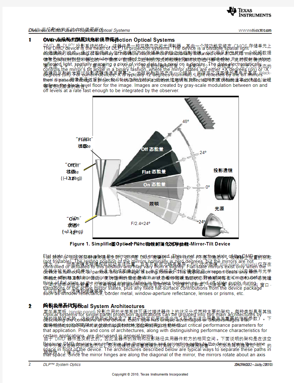
modulator,consisting of an array of movable micromirrors functionally mounted over a CMOS memory cell.Each mirror is independently controlled by loading data into the memory cell below the mirror to steer reflected light,spatially mapping a pixel of video data to a pixel on a display.The data electrostatically controls the mirror’s tilt angle in a binary fashion,where the mirror states are either +X degrees (on)or -X degrees (off).For current devices,X is typically 12degrees (nominal).Light reflected by the on mirrors
then is passed through a projection lens and onto a screen.Light is reflected off to create a dark field,and defines the black-level floor for the image.Images are created by gray-scale modulation between on and off levels at a rate fast enough to be integrated by the observer.
Figure 1.Simplified Optical Function of a 12-Degree-Mirror-Tilt Device Flat state (zero)occurs when the mirrors are not energized.This is not an active state of the DMD mirrors (not tristable).The resting position of the mirrors nominally is zero degrees,but the mirrors are not
controlled or actuated to this position and may vary from it slightly.Flat-state mirrors exist only when the device is turned off,or parked,and no image is being formed.This application report deals only with image effects and interactions between the device and the optical system.Therefore,it is more useful to think of flat state as the integrated energy falling in the area between on-and off-state pupils during transitions of the active mirror states,plus any fixed flat-surface contributions from the device package such as window reflectance,border metal,window-aperture reflectance,lenses or prisms,etc.
2
Projection Optical System Architectures
Optical systems for single-panel projection applications can be grouped into two main architectures by describing the conditions at the device.Each type has unique advantages or disadvantages that determine suitability for a given application,depending on the most critical performance parameters for that application.Pros and cons of architectures,along with distinguishing performance characteristics for certain applications,are discussed in general terms.
Because DMD devices are reflective,the illumination and projection paths to the device share the same space in front of the device.The architectures described below are typical ways to separate these paths in that space.Since the mirror hinges are along the diagonal of the mirror,the mirrors rotate about an axis
DMD 在投影光学系统中的使用概述DMD 在投影光学系统中的使用概述DMD 是 DLP TM
投影系统的核心。该器件是一种双稳态空间光调制器,其由一个按功能安装在 CMOS 存储单元上的微镜阵列组成。通过把数据装入位于微镜下方的存储单元来独立地控制微镜,以引导反射光并把一个视频数据像素空间映射到显示器上的一个像素。数据以二进制的方式对微镜的偏转状态进行静电控制,此时反射镜的状态要么是 +X °(On ),要么是 -X °(Off )。就目前的器件而言,X 通常为 12°(标称值)。处于On 状态的微镜所反射的光穿过投影透镜传递至屏幕上。光被反射后将产生一个暗场,并限定了该图像的黑电平基底 (black-level ?oor)。图像是通过控制On 和Off
状态所占时间比例的长短来调制灰阶,这种灰度调制的速率之快足以让观察者完成图像的融合。Flat 状态 (0)
出现在反射镜未通电之时。这不是 DMD 微镜的一种运行状态(不是三稳态)。微镜静止位置的标称值为 0°,但是微镜未被操控或驱动至该位置,且有可能与之略有差异。Flat 状态微镜 (?at-state mirrors) 仅存在于器件被关断(或停放)、并且未形成图像的时候。本应用报告只讨论镜像效应 (image effects) 以及器件与光学系统之间的相互影响。因此,更为适用的做法是将Flat 状态看作微镜活动状态转换期间落在On 态和Off 态光瞳之间区域中的综合能量,以及来自器件封装的任何固定平面成分(如窗口反射率、边缘金属 [border metal]、窗口-孔径反射率、透镜和棱镜等等)。投影光学系统架构面向单面板
(single-panel)
投影应用的光学系统可通过描述器件上的状况分成两种主要的架构。每种类型具有其独
特的优势或劣势,这些优势或劣势决定了其对于给定应用的适合性(取决于该应用最至关重要的性能参数)。下面将概括地讨论不同架构的优缺点以及针对特定应用的突出性能特征。由于 DMD 器件是反射式的,因此至器件的照明和投影路径共用器件前方的相同空间。下面说明的架构是在该空间中分离这些路径的典型方法。因为微镜铰链沿着微镜的对角线,所以微镜围绕着一个方向与阵列维度成 45° 的轴旋转,(接下页)
11“Flat ” 状态投影透镜
Off 态能量
Flat 态能量On 态能量
照明
光源
“Off ” 状态(-12
°)“On ”
状态 (+12
°)图 1:一个 12° 微镜的简化光学功能
https://www.360docs.net/doc/f76171944.html,
Lamp Color
Wheel DMD
Projection Lens
Integrator Rod Relay Optics
TIR Prism Fold Mirror
https://www.360docs.net/doc/f76171944.html, Projection Optical System Architectures
that is oriented 45degrees to the array dimensions,and steer light in a plane compounded by this axis of rotation.Therefore,for any given location of a projection pupil relative to the device,there exists only one axis for the incident illumination path to the on-state mirrors,as determined by Snell’s Law of reflection.This is the basis for many possible embodiments in detail,all of which must consider the axis of rotation of the mirrors for proper performance.
In general,the device tilt angle sets the maximum useful numerical aperture of the optical system at the device.This prevents overlap of the on-and flat-state pupils for contrast control.This rule of thumb can be “stretched”,depending on performance tradeoffs allowed,but it is a good place to start.How to stretch this rule will be discussed in terms of performance parameters later in this application report.
2.1Telecentric Architectures
Telecentric systems are defined by locating the exit pupil of the illumination system (entrance pupil of the projection lens)at or near infinity from the device surface.The chief rays of every bundle incident on every mirror then are essentially parallel to each other.For the illumination system,this provides uniform angles of incidence across the entire field,creating uniform black levels for the dark field.Typically,the illumination axis is separated from the projection axis by an angle just larger than twice the device tilt angle.The projection axis then is typically perpendicular to the device.If a prism is used to separate the paths (see Figure 2)the telecentric condition also produces uniform distribution of angles of incidence across the antireflection (AR)coated surfaces to avoid spatial nonuniformities in display brightness due to coating-performance variation with angle of incidence.In the example of the total-internal-reflectance (TIR)prism embodiment,the illumination is separated from
the projection path by choosing the angle of the TIR-prism face to be at the critical angle for the illumination path.The uniform angles of incidence and reflection prevent critical angle failure (TIR failure)in the projection or illumination paths through the prism.
One common embodiment of the TIR design is the so-called “Reverse TIR”or RTIR design.This is based on US patent 5309188,which employs a right-angle prism as the TIR prism.The TIR path occurs in the projection path,not the illumination path,which gives it the name “Reverse TIR.”There are several
advantages to this architecture,as well as few disadvantages.Contact TI for additional information on the relative merits of this design.
Figure 2.Generic Telecentric Optical System Components Using a TIR Prism 投影光学系统架构(续上页)并在一个由该旋转轴合成的平面中进行光的引导。因此,对于投影光瞳的任何给定位置(相对于器件),
至On 态微镜的入射照明路径只存在一个轴(由斯涅耳反射定律决定)。这是许多可能的实施例的基础,它们全部必须考虑微镜的旋转轴以实现正确的性能。一般而言,器件的倾斜角度设定了器件光学系统的最大可用数值孔径。这可避免On 态和Flat 状态光瞳的重叠以实现对比度控制。该经验法则可以“通融”(这取决于所容许的性能折衷),但它是一个良好的起点。本应用报告稍后将从性能参数的角度就如何放宽该法则展开讨论。
平行光路架构
平行光路系统是通过把照明系统的出射光瞳(投影透镜的入射光瞳)设置在(或接近于)无穷远处(距离器件表面)来定义的。这样,入射到每个微镜上的每个光束的主射线基本上是相互平行的。对于照明系统,这在整个视场中提供了均匀的入射角,从而为暗场生成了一致的黑电平。通常,照明轴和投影轴的分离角刚刚大于器件倾斜角的两倍。于是,投影轴一般与器件垂直。如果采用棱镜来分离光路(见图 2),则平行光路条件还可在防反射 (AR) 涂层表面上实现均匀的入射角分布,以避免由于涂层性能随入射角的变化而在显示亮度中引发空间不均匀性
。在全内反射 (TIR) 棱镜实施例中,通过把 TIR 棱镜面的角度选择为照明路径的临界角而将照明路径与投影路径分离开来。入射和反射的均匀角度可防止在穿过棱镜的投影或照明路径中出现临界角不足 (TIR 不足) 的情况。TIR 设计的一个常见实施例是所谓的“反向 TIR ”(即 RTIR )设计。其基于第 5309188 号美国专利,采用一个直角棱镜作为 TIR 棱镜。TIR 路径出现在投影路径(而不是照明路径)中,因而得名“反向 TIR ”。该架构具有多项优势和极少的劣势。欲知有关此设计优劣的更多信息请与 TI 联系。
2.1
积分柱
折叠反射镜替续光学器件 灯
TIR 棱镜
色轮投影透镜图 2:采用 TIR 棱镜的通用平行光路光学系统组件
https://www.360docs.net/doc/f76171944.html,
FANS
PROJECTION
LENS
ELECTRONIC ASSY
(DMD)
COLOR WHEEL
INTEGRATING ROD LAMP ILLUMINATION OPTICS
POWER
SUPPLY
TIR PRISM CHASSIS POWER SUPPLY
Projection Optical System Architectures https://www.360docs.net/doc/f76171944.html, 2.1.1Advantages of Telecentric Architecture Some inherent advantages/features of telecentric architecture are:
?Uniform black level due to uniform illumination angles.However,absolute black level is typically higher
(worse)than nontelecentric architectures.This is due to the proximity of flat optical surfaces near the mirror device and the lower overall illumination angles.
?Separation of illumination and projection in glass rather than air space for shorter
overall path length.?Shorter back working distance for projection lens due to path in glass rather than air.?Projection offset for keystone correction can be optimized for application to minimize field of projection
lens,if the application allows.
?Variable projection offset for stacking applications,fixed-install flexibility,etc.can be achieved with prism design.?Zero offset and minimal lens size can be achieved for rear-screen applications with prism design.Rear screens cannot accept high angles of incidence caused by offset due to Fresnel-lens screen limitations.
?Pupil location at/near infinity means no magnification changes
with focus.?Less distortion of illumination light at device (image of integrating rod)due to lower illumination angles
produces less overfill losses,and higher efficiencies.However,some or all of this can be negated by prism coating efficiency losses due to high angles of incidence in the TIR air gap.
?The system can be packaged such that projection-lens offset displacement will not add to package height (see Figure 3).In this case,lens offset is vertical toward the long dimension of the prism,and
does not add height to the package.Also,note that offset direction is away from flat-and off-state light
paths in this configuration,minimizing the chance for stray light to enter the lens aperture and diminish contrast.?Projection and illumination paths (for prism design)can be designed independently,allowing multiple
optical sources and interchangeable lenses.This can speed time to market by having parallel
development of illumination and projection optics.Figure 3.Telecentric TIR Prism Design Layout for Minimum Package Height Due to Projection-Lens
Offset
投影光学系统架构平行光路架构的优势平行光路架构的一些固有优势 / 特性为:? 由于均匀一致的照明角度而实现的均匀黑电平。不过,绝对黑电平通常高于(劣于)非平行光路架构。这是由于平整光学表面靠近微镜器件且总照明角度较低所致。? 在玻璃(而不是大气空间)中进行照明和投影路径的分离以实现较短的总路径长度。? 由于光路在玻璃而非空气中
,因此投影透镜的后工作距离较短。? 用于梯形失真校正的投影偏移可针对应用进行优化,以在应用允许的情况下最大限度地减小投影透镜的视场。? 可利用棱镜设计实现针对堆叠应用 (stacking applications) 的可变投影偏移和固定安装灵活性等。? 利用棱镜设计可实现面向背投式屏幕的零偏移和极小透镜尺寸
。背投式屏幕不能接受由偏移(其源于非涅尔透镜屏幕的局限性)引起的高入射角。? 光瞳位置位于 / 接近于无穷远处意味着放大倍数不随焦点而变化。?
由于照明角度较低而引起的器件上照明光失真的减小(积分柱的图像)可实现较少的溢出损耗 (over?ll losses) 和较高的效率。然而,由于 TIR 空气间隙中的高入射角所造成的棱镜涂层效率损失将使部分或所有这些好处荡然无存。? 系统可以进行封装,这样投影透镜偏移位移将不会导致部件高度的增加(见图 3)。在该场合中,透镜偏移与棱镜的长维度成垂直,并且不会增加封装的高度。另外,请注意在该配置中偏移方向远离Flat 状态和Off 状态光路,从而最大限度地降低了杂散光进入透镜孔径和减小对比度的机率。
? 投影和照明路径(对于棱镜设计)可以单独设计,因而允许使用多种光源和可换透镜。这可以通过照明和投影光学系统的并行开发加快产品上市进程。
2.1.1
积分柱
照明光学器件
电子组件风扇底板
灯
色轮投影透镜TIR 棱镜
电源
电源图 3:针对因投影透镜偏移引起的最小封装高度的平行光路 TIR 棱镜设计布局https://www.360docs.net/doc/f76171944.html,
https://www.360docs.net/doc/f76171944.html, Projection Optical System Architectures Disadvantages of Telecentric Architecture Telecentric architectures have some disadvantages/challenges relative to others:
?Prism-based systems have additional costs,size,and weight of the prism.The TIR air gap has high
angles of incidence,causing some polarization effects and greatly increasing the difficulty of achieving good AR coating designs.TI has reference design coatings available to minimize development efforts for these coatings.
?TIR air-gap coatings have relatively high losses,2%to 3%per surface.These losses tend to offset the gains from reduced distortion overfill losses.However,as the f/No.decreases,these losses tend to decrease as well (coatings become more efficient).?TIR prism surfaces also can produce surface reflections that enter the projection pupil,even though
these surfaces are flat.This is because the intersection of the illumination bundle with these surfaces is displaced from the projection path,creating reflected flat-state light that is displaced from the flat-state pupil location defined by the illumination optics.This light may go to the screen if it can enter the projection lens aperture and pass through the pupil,and it is not controlled by the device state.This also is true for the DMD device window-surface reflections,regardless of architecture.All flat surfaces near the device must have very effective AR coatings to minimize this effect,and their reflections should be thoroughly traced/modeled for possible contrast degradation.The shorter back working distances of telecentric projection lenses,while a benefit to size of the optics,is a detriment to contrast because of the lack of sufficient space to physically separate the on bundle from flat and off bundles.
?One of the strongest factors affecting system contrast is illumination angle to the device.In general,
the higher the angle,the higher the contrast (more detail in Section 4.1.1).Telecentric designs have lower angles of illumination than nontelecentric designs due to lack of additional offset angle.This can reduces inherent contrast compared to nontelecentric,although it inherently is more uniform.Increasing illumination angle alone increases contrast,but also offsets the pupil in the projection lens and introduces vignetting if the numerical aperture of the projection lens is not increased accordingly.However,if the projection lens numerical aperture is increased to avoid vignetting,it can collect more flat-state and stray light from around the device and pass it to the screen,thus potentially defeating the initial intent of improving contrast.It is a tradeoff that is dependent on system requirements.
?As projection offset is added for keystone correction,the elements in the rear of the projection lens
prior to the stop increase in diameter proportionally with the increase in field,because the ray bundles exit the device perpendicular to it.However,selecting only the amount of offset necessary for the application can minimize this.This is not an option for nontelecentric designs.
2.2
Nontelecentric Architectures
Nontelecentric architectures differ from telecentric in that the exit pupil of the illumination path is located a
short,finite distance from the device,and the entrance pupil of the projection lens must be coincident with
it (see Figure 4).Since some degree of vertical projection offset usually is required for most front-screen applications,additional illumination
angle is added to offset the pupil in the vertical axis for the projection lens.This adds additional angle of incidence to the device,increasing inherent contrast,while providing more angular separation of the illumination path from the projection path.This additional angle makes it difficult to use a TIR-type prism for separating the paths,but a field lens (or lenses)can be used instead.Typically,the separation is in air space for minimal cost (fewest optical elements,smallest size elements).However,a field lens in this space reduces path lengths and allows more compact use of the space in front of the DMD.
Since the bundles are converging to the pupil,the angle of incidence of the chief ray for each mirror on the device varies with position in the array.Although this can produce nonuniformity of the dark field (black level),the higher average illumination angles due to the additional offset angle tends to increase the contrast (reduces black level).Also,this convergence to the projection lens minimizes the diameter of the projection lenses on the DMD side of the stop,further enhancing physical separation of the two paths.Some designs use a field lens (or lenses)instead of a prism directly in front of the device to perform the angle separation.The field lens must be on axis with the remainder of the projection lenses,but is shared by the illumination path.This presents some challenges in illumination design since these field lenses also are part of the illumination path,but are off-axis to the DMD and tilted to the illumination path.By
designing the illumination pupil near the stop of the projection lens and folding the illumination path there,a very compact system can be designed if attention is paid to the unique challenges this design presents.
投影光学系统架构
平行光路架构的劣势
相对于其他架构,平行光路架构具有一些劣势 / 难题:? 基于棱镜的系统由于使用棱镜而增加了成本、尺寸和重量。TIR 空气间隙具有高入射角,因而引发了某些偏振效应,并极大地增加了实现良好 AR 涂层设计的难度。TI 可提供参考设计涂层以最大限度地减少针对此类涂层的设计工作量。? TIR 空气间隙涂层的损耗相对较高(按表面计算为 2% 到 3%)。这些损耗往往会抵消由于失真溢出损耗的减低而获得的好处。然而,当焦距比数 (f/No) 减小时,这些损耗往往也将减少(涂层变得更有效)。? 另外,棱镜表面还会产生进入投影光瞳的表面反射,尽管此类表面是很平整的。这是因为照明光束与这些表面的交叉点从投影路径发生了移位,故而产生了从照明光学器件规定的Flat 状态光瞳位置移位的反射Flat 状态光。
如果该光线能够进入投影透镜孔径并穿过光瞳,则其可以到达屏幕,而且它不受器件状态的控制。对于 DMD 器件窗口表面反射情况同样如此,这与架构无关。靠近器件的所有平整表面都必须具有非常有效的 AC 涂层以尽量减轻这种影响,而且应针对可能的对比度下降对其反射进行完全的跟踪
/ 建模。平行光路投影透镜较短的后工作距离虽然有利于缩小光学器件尺寸,但对于对比度则是不利的,原因是缺少用于对On 状态光束与Flat 状态和Off 状态光束进行物理分隔的足够空间。? 影响系统对比度的最强因素之一是至器件的照明角度。一般来说,照明角度越高,对比度越高(更多详情见 4.1.1 节)。平行光路设计由于缺少额外的偏斜角,因此其照明角度低于非平行光路设计。与非平行光路相比,这会降低固有的对比度(尽管其固有对比度更加均匀)。单纯增加照明角度虽可提高对比度,但假如投影透镜的数值孔径未相应地增加,那么这也会使光瞳在投影透镜中发生偏移并引起光晕。不过,倘若增加了投影透镜数值孔径以避免光晕,它就能从器件的周围收集更多的Flat 状态光和杂散光并将之传递至屏幕,从而有可能导致改善对比度的初衷化为泡影。这是一个取决于系统要求的折衷过程。
? 当增加用于梯形失真校正的投影偏移时
,位于投影透镜之后、光阑之前的元件其直径随着视场成比例地增加,因为射线束从与其垂直的器件出射。不过,仅选择应用必需的偏移量可最大限度地抑制这一情况
。对于非平行光路设计而言这并不是一种选项。
非平行光路架构
非平行光路架构不同于平行光路架构之处在于:照明路径的出射光瞳位于离开器件很短的有限距离上,而且投影透镜的入射光瞳必须与之重合(见图 4)。由于大多数前投式屏幕应用都需要某种垂直投影偏移度,因此增加了额外的照明角度,以在用于投影透镜的垂直轴中使光瞳偏移。这给器件增添了额外的入射角,从而提高了固有对比度,同时在照明路径与投影路径之间提供了更大的角间距 (angular separation)。这个附加的角度使得难以采用 TIR 型棱镜来分离照明和投影路径,但可采用场镜(或柔性焦距透镜组)取而代之。通常,路径分离在大气空间中进行以实现成本的最小化(极少的光学元件、极小尺寸的元件)。然而,在这此空间里场镜缩减了路径长度,并可更加紧凑地使用 DMD 前面的空间。由于光束会聚至光瞳,因此用于器件上每个微镜的主射线的入射角随着在阵列中的位置而改变。尽管这会产生暗场(黑电平)的不均匀性,但由于附加偏斜角而实现的较高平均照明角度往往将提高对比度(降低黑电平)。另外,至投影透镜的这种会聚还最大限度地减小了光阑 DMD 侧上投影透镜的直径,从而进一步扩大了两个路径之间的物理分隔。
有些设计直接在器件前面采用场镜(或柔性焦距透镜组)取代棱镜来完成角度分离 (angle separation)。场镜必须与投影透镜其余部分同轴,但被照明路径所共享。这在照明设计中带来了一些难题,因为这些场镜也是照明路径的一部分,但却偏离了 DMD
所在的轴线,并且向照明路径倾斜。通过设计靠近投影透镜光阑处的照明光瞳并在该位置折叠照明路径,在注意到该设计所带来的独特挑战的情况下就能设计出一个非常紧凑的系统。2.1.22.2
https://www.360docs.net/doc/f76171944.html,
Lamp DMD
Integrator Rod
Relay Optics
Folding Mirrors Offset Projection Lens
Color Wheel
Projection Optical System Architectures https://www.360docs.net/doc/f76171944.html, Figure 4.Nontelecentric Optical-System Components 2.2.1Advantages of Nontelecentric Architectures
Some inherent advantages/features of nontelecentric architecture are:
?Typically the fewest number and size of optical elements for lowest cost and fewer optical element losses (higher efficiency),especially when optical offset is required for the application.Even more compact use of space in front of the DMD if a field-lens design is used.
?Offset angle increases illumination angles to higher overall angles of incidence on the device,(see Figure 5).This typically results in the highest overall contrast.The reasons for this effect are discussed in Section 4.1.1.?Inherent keystone correction of the image by placing the DMD device below the optical axis of the projection lens.This generally is required to achieve enough angular separation of the illumination and
projection optics for packaging.
?Smaller optical elements in the rear of the projection lens (before stop)due to finite pupil location.
However,these designs typically have more elements in front of the stop due to limited space behind the stop,so front elements can grow quite large for fast throw ratios and may negate overall savings.
外部图案示例 非平行光路架构的优势非平行光路架构的一些固有优势 / 特性为:? 通常,极少的光学元件数量和较小的光学元件尺寸可实现极低的成本和较少的光学元件损耗(具有较高的效率),特别是在应用需要光偏移的场合。如果采用场镜设计,则可更加紧凑地利用 DMD 前面的空间。? 偏斜角可增大照明角度,从而在器件上提供更高的总入射角(见图 5)。这通常能产生最高的总对比度。产生该效果的原因在 4.1.1 节中讨论。
? 通过把 DMD
器件置于投影透镜光轴的下方而具备了固有的图像梯形失真校正能力。这通常是实现足够的照明和投影光学器件的角间距(用于封装)所必需的。? 有限的光瞳位置使得可以在投影透镜的后方(光阑之前)采用较小的光学元件。不过,由于在光阑的后方空间有限,所以此类设计通常在光阑的前面安置较多的元件,于是前片组 (front element) 会变得相当庞大(以实现快速投射比),并有可能导致总体节省前功尽弃。偏移投影透镜积分柱替续光学器件灯
色轮折叠反射镜图 4:非平行光路光学系统组件
https://www.360docs.net/doc/f76171944.html,
https://www.360docs.net/doc/f76171944.html, Projection Optical System Architectures Figure 5.Effect of Projection Offset on Illumination Angle,Nontelecentric Design,Side View Figure 6.Nontelecentric Optical Layout for Flat Projector Using Reflective and Refractive Illumination
Elements (Isometric View)2.2.2Disadvantages of Nontelecentric Architectures Nontelecentric architectures have some disadvantages/challenges relative to others:
?Nonuniform angles of incidence of the illumination at the device produce variation in the absolute black level,even though the absolute level generally is much lower overall than other architectures.
?Vertical offset requirements increase as f/No.decreases (numerical aperture increases)in order to physically separate illumination and projection optics.This is because the bundles get larger with smaller f/No.The amount of vertical offset generally determines the package height of the projector,since it must be located opposite the illumination input.In contrast to telecentric prism designs,the projection lens cannot be offset toward the illumination to minimize package height (see Figure 6).
However,this characteristic can be taken advantage of in a “tower”style layout,where the projector is
arranged
vertically.?Projection lens elements on the
screen side of the stop tend to become larger than telecentric elements because more of them are located on one side of the stop.Near the front (screen side)of the lens,much of the glass is not used,but truncating the glass to save weight generally is more expensive than practical,especially since it does not reduce packaging height.
?The higher illumination angles distort the image of the integrator rod more severely at the device,
which creates more overfill losses.This can be as much as 10%less efficient than a telecentric design,depending on uniformity requirements and the number and type of illumination elements used.Likewise,these higher angles tend to distort the exit pupil of the illumination system,making it difficult to define for the projection lens design and producing further losses.?Matching pupils at a finite distance from the device requires knowledge of the illumination system in order to design a proper projection lens,and vice-versa.This interdependence can hamper parallel-path development and increase time to market,especially if separate suppliers are involved.?The high offset angle produces projection angles that generally exceed current screen technology for
rear-projection applications.Reducing offset is not an option,nor is variable offset,for nontelecentric
投影光学系统架构
图 5:投影偏移对于照明角度的影响,非平行光路设计,侧视图
图 6:针对采用反射式和折射式照明元件之平面投影机的 非平行光路光学系统布局(等轴视图)非平行光路架构的劣势相对于其他架构,非平行光路架构具有一些劣势 / 难题:? 器件上不均匀的照明入射角度会在绝对黑电平中产生变化
,尽管绝对电平总体而言一般都大大低于其他的架构。? 垂直偏移要求随着焦距比数的减小(数值孔径增大)而提高,以实现照明和投影光学器件的物理分隔。这是因为随着焦距比数的减小光束变大。垂直偏移量通常决定了投影机的封装高度 (package height),因为它必须安放于照明输入的对面。与平行光路棱镜设计不同的是,投影透镜无法向照明路径偏斜来实现封装高度的最小化(见图 6)。
不过,在“塔”型布局中则可利用这一特性,因为此时投影机是垂直安置的。? 光阑屏幕侧上的投影透镜元件往往变得比平行光路元件更大,因为它们当中更多的位于光阑的一侧。在靠近透镜的前部(屏幕侧),玻璃的大部分未使用,但是通过截短玻璃来减轻重量的做法其成本一般比实际的更加昂贵,特别是因为其并未降低封装的高度。? 较高的照明角度在器件上使积分柱的图像发生更严重的失真,从而产生更多的溢出损耗。这最多会导致效率比平行光路设计低 10%(取决于均匀度要求和所用照明元件的数量和类型)。同样,这些较高的照明角度往往会使照明系统的出射光瞳产生失真,从而造成难以针对投影透镜设计进行定义并产生更多的损耗。? 在离开器件的有限距离上匹配光瞳需要掌握照明系统的状况以设计正确的投影透镜
,反之亦然。这种相互依存性会妨碍平行路径开发并延缓产品上市进程,尤其在涉及多家独立供应商的场合。? 高的偏斜角将产生通常会超过面向背投影应用的现有屏幕技术的投影角。对于非平行光路设计,减小偏移不是一种选项,可变偏移也不是。2.2.1
https://www.360docs.net/doc/f76171944.html,
Projection Optical System Design Considerations https://www.360docs.net/doc/f76171944.html, designs.
?Higher illumination angles require more clearance for the window aperture opening so that rays can enter the active area without vignetting or shadowing the active array.This requires more silicon border,or light shield,area around the active array to push bond wires and other structural artifacts out of view under the aperture.This reduces the number of DMD die that can be produced per wafer,
impacting the DMD cost.?More off-state light is trapped in the device by the device window aperture,which can produce undesirable thermal effects and border artifacts.
?Magnification changes slightly with focus of the projection lens.
?Higher offset requirements result in larger field size requirements for the projection lens.Field size is
by far the single most influential design parameter for lens cost and performance.Offset cannot be optimized to minimize field size as for a telecentric prism-based design.
?It is very difficult and expensive to design a constant f/#zoom lens for nontelecentric architectures due to change in stop position.Fixed-stop-position zoom lenses are complex and very difficult to make.
Large zoom ratios tend to produce large brightness variation,accordingly.Movement of the rear group in a zoom lens also is hindered by potential interference with illumination elements,which can make large zoom ratios very difficult.
?Proximity of stop to rear aperture in a projection lens makes it difficult to manage stray light entering
the projection lens.Also,for this reason,no illumination surfaces should be closer to the device than the rear of the projection lens,as they tend to become sources of stray light entering the projection lens.
?Field-lens surface reflections from the illumination path are not controllable by the device state.These reflections can enter the projection lens pupil and deteriorate contrast.Careful modeling of surface reflections with commercially available optical design software is imperative.
?It is very difficult to design lens-shift into a non-telecentric design.The numerical aperture of the projection lens has to be oversized by the amount of lens shift desired.This creates low f/#projection optics and flat state light overlap management issues.Also,it increases the size of the lenses,causing a need for more physical separation (offset)of the illumination and projection ray bundles.
3
Projection Optical System Design Considerations Regardless of the architecture,system design consists of an illumination system and a projection system.In some cases,these systems can be treated independently.In others,particularly those designs having field lenses that are in the path of both the illumination and the projection systems,there is obvious interaction that must be accounted for.The following paragraphs address the design considerations and the components of each system.3.1
Illumination-System Components and Design Parameters
The simple function of the illumination system is to collect as much useable light as possible from a light
source and put it on the device active area (mirror array).The components typically used to do this are:
lamp,reflector,color wheel,integrator,relay and folding optics (including field lenses,if any),and,possibly,a TIR prism.3.1.1
Lamp
Lamp selection depends on several factors:?Projector size/weight/noise goals.Most lamps are rather inefficient at converting electrical energy into visible light.This means there will be a thermal load on the projector from the lamp.In most cases,this load is the highest load in the system.The amount of power (heat)that can be dissipated by the
projector is determined by the number and size of the fans used to cool it,given projector size,weight,and noise requirements.The most efficient lamp,in terms of lumens per watt output collected into the available etendue of the device,is the parameter to optimize.
?
https://www.360docs.net/doc/f76171944.html,mp life requirements vary by application.Consumer applications require very long lamp life to overcome consumer resistance to replacing a high-cost https://www.360docs.net/doc/f76171944.html,mp life of 5000to 10000hours,or more,in the product is required for these applications.Portable projectors,however,typically see relatively infrequent https://www.360docs.net/doc/f76171944.html,mp life of 2000hours in these products can exceed the products’useful lifetime,given the duty cycle.One must be careful to understand what a lamp manufacturer may mean
投影光学系统设计考虑因素 ? 较高的照明角度需要为窗口孔径开口 (window aperture opening) 提供更大的空隙,以使光线能够进入活动区域 (active area) 而不会产生光晕或遮蔽有源阵列的现象。这要求在有源阵列的周围提供更多的硅边缘 (silicon
border) 或光遮蔽区,以把键合线和其他的结构工件 (structural artifacts)
推至视图之外(孔径的下方)。这就减少了每颗晶圆所能生产的 DMD 晶片的数量,从而对 DMD 成本产生影响。
? 器件窗口孔径将更多的Off 态光困于器件之中,这会产生不希望有的热效应和边缘伪像 (border artifacts)。? 放大倍数会随着投影透镜的焦点轻微地变化
。? 较高的偏移要求导致了针对投影透镜的较大视场尺寸要求。对于透镜成本和性能来说,视场尺寸 (?eld size) 是迄今为止最具影响力的设计参数。与基于棱镜的平行光路设计不同,非平行光路架构无法通过偏移的优化来尽量地压缩视场尺寸。
? 由于光阑位置的变化,设计针对非平行光路架构的恒定焦距比数变焦透镜非常困难,而且昂贵。光阑位置固定型变焦透镜结构复杂,非常难以制作。大的变焦比往往会相应地产生大的亮度变化。另外,变焦透镜中后片组 (rear group) 的移动还将受到照明元件潜在干扰的妨碍,这会使得大的变焦比非常难以实现。? 投影透镜中光阑与后孔
(rear aperture) 靠近,因而难以管理进入投影透镜的杂散光。同样由于这个原因,所有的照明表面均不得比投影透镜的后部更接近器件,因为它们往往会成为进入投影透镜的杂散光的来源。
? 来自照明路径的场镜表面反射不能利用器件状态来控制
。这些反射会进入投影透镜光瞳并损害对比度。必须采用市售的光学设计软件进行谨慎的表面反射建模。? 在非平行光路设计中很难设计透镜移位。必须依据所需的透镜移位量采用超大的投影透镜数值孔径。这产生了低焦距比数投影光学器件和Flat 状态光重叠管理问题。另外,它还增大了透镜的尺寸,因而导致需要提供更大的照明和投影射线束物理分隔(偏移)。投影光学系统设计考虑因素不管采用何种架构,系统设计都包括一个照明系统和一个投影系统。在某些场合中,这些系统可以分开处理。而在其他的场合中(特别是那些在照明和投影系统的光学路径中运用了场镜的设计),则存在着必须考虑的明显的相互影响。下面的段落将阐述设计考虑因素以及每个系统的组件。
照明系统组件和设计参数照明系统的简单功能是尽多地从光源收集可用光并将其置于器件的活动区域(微镜阵列)。
通常用于完成此项功能的组件为:灯、反射器、色轮、积分器、替续和折叠光学器件(包括场镜,如果有的话),很可能还有 TIR 棱镜。灯灯的选择取决于若干个因素:
? 投影机尺寸 / 重量 / 噪声目标。在把电能转换为可见光方面,大多数的灯均效率低下。这意味着灯将给投影机施加一个热负载。在大部分场合中,该负载是系统中的最高负载。对于给定的投影机尺寸、重量和噪声要求,投影机所能耗散的功率
(热量)由用于为其提供冷却的风扇的数量和尺寸决定。灯的效率(用收集到器件可用光展量中的每瓦输出流明来表示)是需要优化的参数。
? 寿命。灯的寿命要求因应用而异。消费类应用需要十分长久的灯寿命,以克服消费者对于更换高成本灯的抵触情绪。此类应用的产品中所采用的灯其寿命要求为 5000 到 10000 小时或更长。然而,便携式投影机的使用频度通常不高。鉴于这样的工作周期,在此类产品中,2000 小时的灯寿命有可能超过产品本身的有效寿命。必须谨慎地理解灯制造商所指的灯寿命与产品本身对于灯寿命的要求这两者所表达出的不同含义。(接下页)3
3.1
https://www.360docs.net/doc/f76171944.html,
https://www.360docs.net/doc/f76171944.html, Projection Optical System Design Considerations by lamp life,versus what a product requirement for lamp life means.Typically,product lamp life means
no less than 50%of initial product brightness output after the specified lifetime under certain duty cycle requirements with few,if any failures.Manufacturers typically specify catalog lamp life in terms of 50%of a sample lot still running after a specified period of time,usually under ideal thermal conditions.These are very different requirements,and both parties must understand what is meant or needed.?Spectral content.The output spectrum of the lamp must be balanced into useable color space in the projector by the color-wheel.The efficiency of this conversion can vary greatly from lamp to lamp.TI has a color-wheel design/modeling tool that can compare the relative efficiencies of lamps after color-wheel conversion.The results often are not obvious.As a rule of thumb,the closer the CCT of the lamp is to the desired whitepoint of the projector,the more efficient the lamp/color-wheel combination will be.?Commutation and arc stability.Whether the lamp is ac or dc,and whether it has some means of
preventing arc jump or arc flicker,can be important factors in the application.
?Efficacy at small etendue.Like most projection display technologies,device panel size (area)
combined with the maximum allowable numerical aperture (solid angle)determines the system etendue.This typically requires small plasma-arc sources,volumetrically constrained under high
pressure.Matching the lamp etendue to the system etendue is the goal for maximum efficiency.
?Most lamps have requirements for operating position relative to gravity.Make sure the projector layout does not violate lamp-orientation requirements in all end-use applications.
3.1.2Reflector The lamp reflector collects the light from the lamp and directs it into the illumination optics.Characteristics
of the reflector are:
?Cold-mirror dichroic coating to minimize downstream UV and IR loads on optical components and the
DMD.
?Elliptical (or similar)shape.Most single-panel DLP systems utilize an elliptical reflector to focus the light into a small spot on the color wheel.Systems that use parabolic shapes must add condenser optics between the lamp and color wheel to focus the lamp.As the lamp arcs approach a point source,the pure ellipse becomes more difficult to improve upon.However,lamp bulb walls may have thickness and shape variations that can cause distortions that can be corrected by higher order reflector curves.?It is the function of the reflector to minimize the spot size at the wheel such that the transition spokes between colors of the wheel can traverse the extent of the spot in the shortest amount of time possible.Although the mixed-color light in the spoke transitions eventually is combined into useable light,the
angle subtended by the spoke transitions becomes a larger percentage of the total 360degrees as the
radius of the wheel is reduced.This leaves less time for each of the pure primary colors,eventually approaching a limit determined by the amount of time required to fit all the bits required into each particular color.This time also is a function of the lamp spectral balance,so it is a system-level problem to optimize.The TI color-wheel modeling tool should be applied to this problem.
?The reflector must contain bulb rupture.Also,some means of protecting the color wheel from damage due to bulb rupture may be a part of the reflector assembly,such as a cover glass at the reflector exit.A cover glass is also a good place for UV and IR filters,if needed.The reflector volume usually determines the thermal environment for the lamp,and,therefore,has a great impact on lamp life in the projector.Some provisions for cooling the lamp burner may be required as the reflector volume is reduced for small products.?Reflector surface quality becomes increasingly important as reflector surface area is reduced for small reflectors.Surface imperfections usually are a function of the manufacturing process,and become a relatively larger percentage of the total area as the reflector area is reduced for small products.?Avoid placing
optical elements,such as lenses or windows,between the reflector face and the reflector focus.If necessary,place them as close to the reflector face or the focus as possible,and/or tilt
them so that the reflected energy does not go back along a path that will focus on the lamp burner electrode tips or wires.Elements near the midway point between the face and the focus reflect lamp energy back that can focus on or near the tip of the lamp burner,unless tilted.This can cause accelerated lamp failures due to electrode oxidization or thermal gradients.For example,this can occur if a condenser lens is added to slightly change the numerical aperture of an off-the-shelf reflector rather than designing and tooling a custom reflector.
?Be aware that the color wheel reflects a load back into the lamp/reflector assembly equal to the
complement of the wheel efficiency,which can be as much as 2/3of the lamp output.This definitely
投影光学系统设计考虑因素
? (续上页)通常,产品用灯的寿命指的是:在特定的工作周期和故障极少(如果有的话)的情况下,在规定的寿命结束之后产品的亮度输出不低于初始值的 50%。而灯的制造商通常规定的是样品灯寿命 (catalog lamp life),指的是在理想的热条件下,一批样品在经历了规定的时间段之后仍有 50% 可以正常运行。这些是迥异的要求,双方必须理解彼此真实的含义或需求。? 光谱含量
。必须利用色轮将灯的输出光谱均衡地散布于投影机中的可用色空间。这种转换的效率在灯与灯之间会存在着极大的差异。TI 拥有一种色轮设计 / 建模工具
,其能够在色轮转换之后比较灯的相对效率。结果常常是不明显的。作为经验法则,灯的 CCT 越接近投影机期望的白点 (whitepoint),那么灯 / 色轮组合的效率就将越高。? 换向和光弧稳定性。不管灯是交流型直流型,也不管它是否具备某些用于避免光弧跳跃 (arc jump) 和光弧闪烁 (arc ?ickering)
的方法,它们都会是应用中的重要因素。? 小光展量 (small etendue) 条件下的效能。和大多数投影显示技术一样,器件面板尺寸(面积)与最大容许数值孔径(立体角)一道共同决定了系统光展量。这通常需要采用小型等离子体光弧光源(在高压之下体积受限)。使灯的光展量与系统的光展量相匹配是实现最大效率的目标。
? 大多数灯都具有相对于重力的工作位置要求。在所有的终端应用中皆应确保投影机的布置不会违背灯的取向要求。
反射器
? 灯反射器负责收集来自灯的光并将之引导至照明光学器件。反射器的特性为:
? 冷反射镜二向色涂层用于最大限度地降低光学组件和 DMD 上的下游 UV 和 IR 负载。? 椭圆(或相似的)形状。大多数单面板 DLP 系统都使用一个椭圆形反射器来把光聚焦到色轮上的一个小点。采用抛物线形反射器的系统必须在灯和色轮之间增设聚光器以实施灯的聚焦。当灯光弧接近一个点光源时,纯椭圆变得更难改进。然而,灯泡壁可能具有会引起失真的厚度与形状变化,这可以利用较高阶的反射曲线加以校正。
? 最大限度地减小色轮上的光点尺寸是反射器的功能,这样色轮彩色之间的过渡轮辐 (transition spokes) 就能在尽可能短的时间里穿过光点的范围。虽然轮辐过渡 (spoke transitions) 中的混色光最终组合成可用光,但是当色轮的半径减小时,由轮辐过渡所包夹的角度在整个 360° 中所占的百分比将增大。这就为每种纯基色留下了较少的时间,最终接近一个限值,该限值由把所有需要的位放入每种特定彩色所需的时间量决定。该时间也是灯光
谱平衡的一个函数,因而是一个需要加以优化的系统级问题。应采用 TI 色轮建模工具来解决此问题。? 反射器必须抑制灯泡破裂。而且,有些用于防止色轮因灯泡破裂而受损的方法也许是反射器组件的一部分,比如:位于反射器出口的保护玻璃。如果需要,保护玻璃也可以是供布设 UV 和 IR 滤光镜的适宜之地。反射器的体积常常决定了灯所处的热环境,因此其对投影机中的灯寿命具有巨大的影响。当反射器的体积针对小型产品而缩减时,可能需要采取一些用于冷却灯心 (lamp burner) 的措施。? 当反射器的小型化导致反射器表面面积缩减时
,反射器表面质量变得日益重要。表面缺陷常常与制造工艺有关,而且当反射器面积针对小型产品的需要而缩减时,其在总面积中所占的百分比相对较大。? 避免把光学元件(例如:柔性焦距透镜组或窗口)安放在反射器正面和反射器焦点之间。如果有必要,可将其放置在尽可能靠近反射器正面或焦点的地方和 / 或使其倾斜,这样反射能量就不会沿着一条路径返回而集中于灯心电极头或电极丝上。靠近反射器正面和反射器焦点之间的中间点的光学元件将灯管能量反射回来,这些反射能量会集中在(或靠近)灯心的尖端,除非把光学元件倾斜。这会由于电极氧化或热梯度的原因而加速灯的失效。
比如,倘若不是设计和加工定制反射器,而是增设一个聚光透镜以轻微改变现成有售反射器的数值孔径,就会
出现这种情况。? 必需意识到,色轮将一个负载反射回灯 / 反射器组件(等于色轮效率的补足),其可高达灯输出的 2/3。这肯定会影响灯 / 反射器组件中的热环境,在设计中必须加以考虑。
https://www.360docs.net/doc/f76171944.html,
Projection Optical System Design Considerations https://www.360docs.net/doc/f76171944.html, affects the thermal environment in the lamp/reflector assembly,and must be accounted for in the
design.?
The reflector curve has a large impact on the shape of the far-field angular distribution of the
lamp/reflector output.This angular-weighted distribution affects the design of the color wheel filters,and should be accounted for in pupil-weighted MTF calculations for projection-lens performance.
3.1.3Color Wheel
The design of a color wheel is covered in a separate application note.Optically,it is a series of dichroic
filters arranged in segments around the diameter of the wheel,which pass red,blue,green,yellow,magenta,cyan,or white light as the DMD device sequence requires.Some optical considerations are:?Dichroic filter performance as a function of angle of incidence.The smaller the spot on the color wheel,
the better for timing purposes.However,usually this is achieved by increasing the speed,or numerical aperture,of the lamp reflector.This creates increasingly higher angles of incidence on the filters,
changing
performance and softening cutoff slopes in the process.The cost of improving cutoff performance with more coating layers should be weighed against the spot-size savings when considering going faster than about f/1at the color wheel.?Location of the wheel.In all the system configurations shown,the color wheel is placed prior to the integration rod,immediately after the lamp.In field-sequential applications
using a color wheel,it is more efficient to transition the color-wheel spokes through the lamp spot rather than through the integrated output of the integrator rod.This is because the lamp spot usually is much more spatially compact than the output of the rod;otherwise,there would not be a need for the rod.Also,the spoke light-recapture algorithm,if used,works better if the spoke transition is spatially mixed before reaching the device.
?The wheel should be located as close as is practical to the integrator entrance face,considering wheel
runout,vibration/shock loads,and positional tolerances.Typically,1mm spacing is adequate.This small space has little effect on spot size at the wheel.Typically,the focus beam waist of the lamp in this Z-axis is much longer than this space.
?Placing the wheel prior to the integration rod also relieves significant thermal load on the rod.One thermal benefit of the wheel is that the heat from the focused spot is distributed in an annular ring of
much larger surface area due to the rotation of the wheel,and there is some forced-convection cooling due to the rotation as well.However,this benefit shrinks as the wheel diameter decreases,so thermal loading of the color-wheel motor should be monitored in system design.3.1.4
Integrator The integrator function spatially redistributes the image of the arc from a highly peaked distribution to a
more uniform,flat-topped distribution,resulting in relatively flat spatial distribution of light on the screen
(see Figure 7).As lamps become more etendue matched to the devices,they become more spatially
nonuniform at the focus of the reflector,so some kind of integration technique always is used on DLP products today.Although frequently used in LCD products,lens-array type integrators
(fly-eye)are not a good choice for DLP projectors except in cases where absolute minimal path length is required.A rod
integrator,solid or hollow,is the best choice for reasons described in the following paragraphs.Types and
characteristics of various integration techniques are:?Lens arrays.Lens arrays typically are two molded lens-array plates spaced a certain distance apart.Typically,they are used with a parabolic reflector in near-collimated space to facilitate design.This is convenient for three-panel LCD or DLP products that do not require a focus through a sequential color wheel,but not for single-panel DLP products.Typically,lens arrays are less efficient than a rod-type integrator for several reasons,most having to do with manufacturing techniques.Most are molded glass,
requiring small drafts between lens elements in order to release from the mold.This area represents lost light.This loss is repeated for every lens element on every plate.Then,the array on the first plate must accurately align with the array on the second plate;any misalignment causes further losses.Then,each image formed by the lens pair from each plate must accurately image to the device array.It is not possible to align each image formed by each pair independently because they are molded together into plates,the image must be large enough that any tolerances in position of the device array relative to the lens array (and vice-versa)will be accounted for.All of these tolerance buildups result in larger losses relative to a single rod image.And finally,the quality of collimation of the incoming light beam determines the amount of crosstalk between lens pairs.When a skew ray from one lens enters the adjacent lens (crosstalk)instead of the one directly paired with it,this ray is lost to
投影光学系统设计考虑因素 ? 反射器曲面对于灯 / 反射器输出的远场角分布具有很大的影响。该角度加权分布影响了色轮滤光镜的设计,而且在针对投影透镜性能的光瞳加权 MTF 计算中应给予考虑。
色轮? 色轮的设计在一篇单独的应用笔记中进行了论述。从光学的角度来说,它是一连串以节段的形式围绕轮的直径排列的二向色滤光片,其可按照 DMD 器件序列的要求传递红、蓝、绿、黄、品红、青或白光。一些光学考虑因素为:? 二向色滤光片性能与入射角的函数关系。色轮上的光点越小,对于定时目的而言就越好。然而,这常常是通过增加灯反射器的速度或数值孔径来实现的。这将在滤光镜上产生越来越高的入射角,并在此过程中改变性能和减缓截止斜坡 (cutoff slope)。当考虑将色轮上的速度提升至高于约 f/1 时,应在“增加涂层以改善截止性能”(因而造成成本增加)与“压缩光点尺寸”两者之间进行权衡。? 色轮的位置。在示出的所有系统配置中,色轮都是安置在积分柱之前,且紧接在灯之后。在采用色轮的场序制应用中,通过灯光点 (lamp spot) 转变色轮轮辐要比通过积分柱的积分输出更加有效。这是因为从空间的角度来看,灯光点要比积分柱的输出紧凑得多。否则就不需要积分柱了。另外,倘若轮辐过渡在到达器件之间进行空间混合,那么采用轮辐光重获算法 (light-recapture algorithm) 的话效果将更好。? 考虑到色轮偏摇度、振动 / 冲击负载和位置公差,在实际条件允许的情况下,应将色轮安放在尽可能靠近积分器入射面的地方。通常 1 mm 的间隔就足够了。这种狭小的距离对于色轮上光点尺寸的影响微乎其微。与该距离相比,这个 Z 轴中的灯聚焦光束腰一般长得多。? 把色轮安置于积分柱之前还可以释放积分柱上的大量热负载。色轮对于散热的一项优势是:由于色轮的旋转,来自于焦点的热量将分布在一个表面积大得多的孔环 (annular ring) 中,而且同样由于这种旋转,会产生某种强制对流冷却效果。不过,这项优势将随着色轮直径的减小而减弱,因此在系统设计中应监视色轮电机的热负载。积分器? 积分器的功能是对光弧的图像进行空间再分布,使之从一种高尖峰型分布变为一种更加均匀的平顶型分布,从而在屏幕上实现光的相对平坦的空间分布(见图 7)。随着灯与器件的光展量日益匹配,它们在反射器焦点处的空间分布变得更加不均匀,因此在如今的 DLP
产品上始终运用了某种积分方法。透镜阵列型积分器(复眼)虽然常用于 LCD 产品,但其对于 DLP 投影机却并不是合适的选择(需要绝对最小路径长度的场合除外)。出于下面段落所述之原因,光积分棒(实心或空心)是最佳的选择。各种积分方法的类型和特征为:
?
透镜阵列。透镜阵列通常是间隔一定距离的两个模制透镜阵列板。一般地,它们与一个位于近准直空间 (near-collimated space) 中的抛物线反射器一起使用以简化设计。虽然这对于不需要通过顺序色轮 (sequential color wheel) 实现聚焦的三面板 LCD 或 DLP 产品而言很方便,但是对于单面板 DLP
产品则不然。透镜阵列的效率通常不及棒型积分器,原因大多与制造技术有关。它们大部分是模制透镜,因而在透镜元件之间需要设置小的锥度以便脱模。这个区域会造成光损失。每块透镜阵列板上的每个透镜元件都在重复着这种光损失。于是,第一块板上的阵列必须精确对准第二块板上的阵列;任何对准偏差都将引起更多的光损失。接着,由每块阵列板的透镜对所形成的每幅图像必须准确地映像至器件阵列。不可能单独地对每对透镜形成的每幅图像实施对准,因为它们是一起模制到阵列板中的,图像必须足够大,这样器件阵列相对于透镜阵列的任何位置公差(反之亦然)都将被列入考虑范围。所有这些公差的累积将导致较大的光损失(相对于采用单根光积分棒时的图像)。最后,输入光束的准直度质量决定了透镜对之间的串扰量。当来自一个透镜的斜射光没有进入一个与之直接配对的透镜,而是进入了相邻的透镜(串扰)时,该光线因溢出而损失掉。3.1.3
https://www.360docs.net/doc/f76171944.html,
https://www.360docs.net/doc/f76171944.html, Projection Optical System Design Considerations overfill.
?Solid-glass-rod integrators.These are commonly used,but increasingly are being replaced by hollow mirror-integrator tunnels.They both work on the same principle of creating reflections inside the rod to spatially randomize the input to a more uniform output,without changing the numerical aperture.The solid glass rod does this by total internal reflection off the glass/air sides.The number of reflections inside the rod is a function of the index of the glass,the numerical aperture of the input,and the cross section and length of the rod.It is somewhat challenging to mount an unclad glass rod in a system,because every point of contact with the wall creates TIR failure where light exits the rod,causing throughput loss as well as a concentrated thermal load at the point of contact.Also,the rod entrance and exit faces should be AR coated without spilling over to the sides,which can be a relatively expensive process.Since the output face also is in focus on the device (and therefore screen),any imperfection or dust particle that settles on this face will be imaged to the screen and appear as image defects.Also,the number of reflections per unit length of rod is lower in glass than in air due to the
index of the glass,requiring a longer length of rod for the same amount of integration.Finally,safety bevels on the faces usually are required to avoid chipping,but increase overfill losses in proportion to their size.?
Theoretically,TIR is more efficient than a mirror reflection,so,for relatively long rod lengths and/or
high-powered systems,glass (or fused silica or quartz)is still the preferred choice due to efficiency and thermal effects.Exit-face dust protection can be provided by abutting or attaching a thick plate to the exit face,thus displacing the dust to an out-of-focus position,or by sealing the space between the exit-face and the first element downstream.?Hollow mirrored tunnels increasingly are used in smaller systems for several reasons.First,they produce more integration per unit length because they are working in air (index =1)instead of glass.Hollow tunnels can be shorter than solid rods for the same application.Second,
there is no output face to collect dust or imperfections to image to the screen.Third,there are no faces to AR coat,which makes the overall efficiency about the same for short lengths.Fourth,they are much simpler to mount because there are no TIR failure points.The only drawback is the tendency to operate at higher temperatures due to the absorption losses in the mirror coatings,which can weaken adhesives if used to assemble the mirror sections,or create localized heating issues.Also,sizing adjustments are easier and faster to implement with a tunnel.
?
Design considerations.Typically,TI recommends an integrator length that will produce an
approximately 4x 5array of arc images for acceptable uniformity,depending on application.Some applications require up to 8x 10array images or more,especially if there is arc flicker or arc jump to mitigate.It is recommended that uniformity be modeled in optical design software to determine the optimum length based on the arc profile,far-field distribution,lamp-focus position,and length of the integrator.As the rod length is decreased,the sensitivity of uniformity to lamp-focus tolerances becomes more critical.?An image is created in the array each time the marginal ray crosses the optical axis.The array can be observed in any pupil of the illumination relay,where there are multiple images of the cross section of the rod in a rectangular array,each image containing an image of the arc as viewed by the angles subtended to the arc from that image.The outer array images represent the highest angles of light from the lamp reflector;the interior array images are the shallowest angles.In the center,typically there is a dark spot representing the innermost angles shadowed by the lamp electrodes.?Cross-section sizing.The size of the cross section is determined by optical performance of the illumination relay,the assembly tolerances,and the size and tolerance of the device.At a minimum,the size should prevent any chromatic artifacts or vignetting in the image at the device (screen).Tolerance stackups in the size,position,and magnification of the image of the integrator through the optical system,and the mechanical tolerances from the integrator mount to the device die in the DMD package itself,must all be accounted for.This can be done by oversizing the integrator cross section to always allow the device to be in the image of the integrator,but it results in large overfill lumen loss (efficiency)because the area outside the device contains light that otherwise could be useable.The loss is even more significant for highly uniform profiles created by longer integrator lengths,because the outer areas are nearly as bright as the central areas.A better,more common approach is to size the cross section for minimum overfill and adjust the position of the image to the device at some step in projector assembly.This is a relatively simple process (see Figure 4),and it eliminates many tolerance stackups to allow maximum brightness.
投影光学系统设计考虑因素
? 实心玻璃棒形积分器。此类积分器是目前常用的,但正在越来越多地被空心反射镜隧道积分器所取代。这两种积分器的工作原理相同,即:在棒的内部产生反射以通过空间随机化处理将输入变为一个更加均匀的输出,而并不改变数值孔径。实心玻璃棒利用玻璃 / 空气侧的总内部反射做到了这一点
。棒内的反射次数是玻璃的折射率、输入的数值孔径、以及棒的横截面和长度的一个函数。在系统中安装一个无包层的玻璃棒有点棘手,因为与内壁接触的每个点都会在光线从棒中射出的地方产生 TIR 失效,从而引起吞吐量损失以及触点上的一个集中热负荷。另外,对棒的入射面和出射面还必须涂覆防反射层(且不漫溢到各边),这会是一道相对昂贵的工艺。由于输出面在器件上也是焦点对准的(因而在屏幕上也是),
因此该输出面上的任何瑕疵或者停落于其上的灰尘粒子都将被映像到屏幕并显现为图像缺陷。而且,由于玻璃折射率的原因,每单位棒长在玻璃中的反射次数低于在空气中的反射次数,因此对于相同的积分量所需的光积分棒较长。最后,常常需要在表面上设置安全倒角 (safety bevels) 以避免出现剥落 (chipping),但溢出损失将随着其尺寸成正比地增加。? 从理论上说,TIR 比镜面反射更加有效,因此,对于相对较长的光积分棒和 / 或高功率系统,玻璃(或者熔融硅石或石英)因其效率和热效应仍然是优先选择。可以通过把一个厚板紧靠或连接至出射面(从而将灰尘转移至一个离焦位置)、或者将出射面与第一个下游元件之间的空间密封起来以提供出射面的防尘。
? 出于多种原因,在较小的系统中越来越多地使用装有反射镜的空心隧道 (hollow mirrored tunnel) 积分器。首先,由于它们工作于空气(折射率 = 1)而不是玻璃中,因此每单位长度可产生更多的积分。其次,没有输出面,因此不会有灰尘或瑕疵被映像至屏幕。第三,没有至 AR 涂层的面,因而可在长度很短的情况下保持总效率基本不变。第四,安装大为简化,因为没有 TIR 失效点。唯一的缺点是有在较高温度下操作的倾向,这是因为反射镜涂层中的吸收损失所致,其会削弱粘合剂(如果采用粘合剂来组装反射镜部分的话
),或者产生局部加热问题。另外,采用隧道积分器来实施尺寸调整 (sizing adjustments) 更加简便快捷。? 设计考虑因素。通常,TI 建议采用一个将产生具有可接受均匀性的约 4 x 5 光弧图像阵列的积分器长度(取决于应用)。有些应用需要多达 8 x 10 的阵列图像(或更多),尤其是当存在需要减轻的光弧闪烁或光弧跳跃时。建议在光设计软件中进行均匀性的建模,以根据光弧轮廓 (arc pro?le)、远场分布、灯焦点位置和积分器的长度来决定最佳的长度。当积分柱长度减小时,对于灯焦点容差 (lamp-focus tolerance) 的均匀性敏感度变得更加至关紧要。? 每次边缘光线穿过光轴时将在阵列中生成一幅图像。该阵列可在照明继电器的任何光瞳中进行观察,这里有一个矩形阵列中的积分柱之横截面的多幅图像,每幅图像包含一幅光弧图像,这是利用与来自该图像的光弧所对的角观察到的。外部阵列图像代表来自灯反射器的光的最高角度;内部阵列图像则是最浅的角度。在中心部分,通常有一个暗点,其代表了被灯电极所遮蔽的最深的角度。
? 横截面尺寸。横截面的尺寸由照明继电器 (illumination relay) 的光性能、装配误差、以及器件的尺寸和容差决定。最低限度,该尺寸应防止在器件(屏幕)上的图像中出现任何的色伪像或光晕。尺寸、位置和通过光学系统后积分器图像放大倍数中的累积公差,以及由安装至 DMD
封装本身中的器件芯片的积分器带来的机械公差,都必须加以全面考虑。这可以通过采用超大的积分器横截面(以始终允许器件处于积分器的图像中)来实现,但这将造成很大的溢出光通量损失(效率下降),因为位于器件外部的区域所包含的光原本是可以利用的。对于由较长的积分器产生的高度均匀的轮廓来说,这种损失将更大,原因是外部区域几乎与中心区域一样明亮。一种更好、更常用的方法是通过合理确定横截面的大小以实现最小的溢出,并在投影机装配的某道工序中将图像
的位置调整至器件。这是一种相对简单的工艺(见图 4),而且它消除了许多的累积公差,可提供最大的亮度。https://www.360docs.net/doc/f76171944.html,
020000
4000060000
80000
100000
1200001400001600005
4
3
2
1
1
-1
-2
-3
-4
-5
-5
-3
-1
1
3
5
140000-160000120000-140000100000-12000080000-10000060000-8000040000-6000020000-400000-20000
Projection Optical System Design Considerations https://www.360docs.net/doc/f76171944.html, (Highly peaked Gaussian profile maps directly to screen uniformity unless redistributed by spatial integration.)Figure 7.Spatial Irradiance Distribution of a Small-Arc Lamp at Focus of Elliptical Reflector Before
Integration (left,at rod input)and After Integration (right,at rod output)
3.1.5Relay/Folding Optics
Relay optics can be reflective,refractive,or a combination of the two.In applications using a rod or tunnel integrator (nearly all single-panel DLP applications),the relay is a classical Abbe configuration,forming an image of the rod/tunnel face at the device plane.Also,this creates a convenient field stop at the device,minimizing thermal problems and border artifacts due to illumination overfill.The function of the relay is to transfer as much of the light from the output of the integrator to the device with acceptable uniformity,and to match the numerical aperture at the integrator to the numerical aperture of the projection with appropriate magnification.Whether the relay is telecentric or not at the device,it always should be telecentric at the integrator to avoid color and spatial uniformity https://www.360docs.net/doc/f76171944.html,e of folding mirrors and the overall path length usually are determined by packaging constraints or goals,and vary from product to product.One possible benefit of curved reflective elements in the illumination relay is that these can perform the functions of both a lens and a fold mirror in one compact element.However,large off-axis angles often required for folding can have detrimental effects on uniformity,distortion,spectral transmission,polarization,and other aberrations of a curved mirror.Irradiance profile at the device always should be modeled by suitable software programs.Other considerations are:
?Illumination relays must be optimized for minimal optical blur at the outer edges of the integrator rod or
tunnel field.This is contrary to a typical imaging system,where performance usually is optimized near the center of the field.Proper weighting of the field during design optimization maximizes brightness by minimizing blur at the edges of the image,which reduces the size of the integrator cross section and,thus,the amount of overfill.
?Integrator sizing also must account for Scheimpflug distortion caused by the angle of incidence of the
illumination relay to the device.Decentering,tilting,aspherics,Scheimpflug correction of the exit face
of the integrator,or some combination of these can be used to improve this in some cases.Minimizing this distortion is important for efficiency and thermal reasons.
?Typically,distortion overwhelms blur for nontelecentric illumination relays due to the much higher
illumination angles to the device created by the additional offset angle.?Telecentric relays have lower illumination angles,and thus lower distortion,but may require more elements to control blur better because distortion is lower.?One benefit of field-lens architectures is that usually there are more optical elements (surfaces)in the illumination path to help optimize blur (usually a chromatic aberration).The field lens itself is decentered and tilted with respect to the illumination optical axis,which may help
correct Scheimpflug distortion.?Vignetting can be applied to reduce the diameters of the elements required because the illumination is centered on the device.Uniformity goals should not be compromised,and brightness at the ANSI measuring points for lumens should be maintained.Keep in mind,however,that ray bundles are
投影光学系统设计考虑因素替续 / 折叠光学器件替续光学器件 (relay optics) 可以是反射式、折射式或此二者的组合。在采用棒状积分器或隧道积分器的应用(几乎所有的单面板 DLP 应用)中,继电器是一种经典的阿贝 (Abbe) 配置,其在器件平面上形成棒状 / 隧道积分器表面的图像。而且,这在器件上产生了一个方便的视场光阑,从而最大限度地减少了热问题以及因照明溢出而引起的边缘伪像 (border artifact)。继电器的功能是以可接受的均匀性将来自积分器输出的光尽可能多地转移至器件,并使积分器上的数值孔径与具有合适放大倍数的投影透镜的数值孔径相匹配。不管继电器在器件上是否为平行光路,其在积分器上始终应为平行光路,以避免发生彩色和空间均匀性问题。折叠反射镜的使用以及总的路径长度常常由封装限制条件或目标决定,而且因产品而异。在照明继电器中采用弯曲型反射元件的一项可能的优势是其能够利用单个紧凑的元件同时实现透镜和折叠反射镜的功能。然而,折叠经常需要的大离轴角会对均匀性、失真、光谱透射、偏振和曲面反射镜的其他像差产生不利的影响。应始终利用合适的软件程序对器件上的照射度侧影 (Irradiance pro?le) 进行建模。其他的考虑因素是:? 必须优化照明继电器以最大限度地抑制棒状积分器或隧道积分器视场外缘上的光学降晰 (optical blur)。这与典型成像系统的做法正好相反,后者的性能常常是在靠近视场中心处进行优化。在设计优化过程中实施正确的视场加权可通过尽量减少图像边缘处的降晰(这缩小了积分器横截面的尺寸,从而减少了光溢出量)来实现亮度的最大化。? 积分器的尺寸确定还必须考虑由照明继电器至器件的入射角所引起的斯凯姆普夫拉格失真 (Scheimp?ug distortion)。在有些场合中,可采用离心、倾斜、非球面镜、积分器出射面的斯凯姆普夫拉格校正或这些举措的某种组合对此加以改进。由于效率和热性能方面的原因,尽量减小这种失真是很重要的。? 通常,由于额外的偏斜角产生了高得多的至器件的照明角度,因此对于非平行光路照明继电器而言失真压倒了降晰。? 平行光路继电器具有较低的照明角度,因此失真较低,但有可能需要使用更多的元件以更好地控制降晰(因为失真较低)。? 场镜架构的一项优势是在照明路径中存在更多的光学元件(表面),可帮助优化降晰(通常是一种色差)。场镜本身是偏心和倾斜的(相对于照明光轴),这或许有助于校正斯凯姆普夫拉格失真。? 可应用渐晕 (vignetting) 以减小所需的光学元件直径,因为照明集中于器件。均匀性目标不应牺牲,并应保持用于流明的 ANSI
测量点上的亮度。不过需记住,射线束利用器件的反射实现反向,并将内部光线逐出(反之亦然)。(接下页)3.1.5(高尖峰的高斯剖面直接映射到屏幕均匀性,除非利用空间积分进行重新分布。)
图 7:积分前(左侧,在柱输入)及积分后(右侧,在柱输出)小型弧光灯在椭圆形反射器焦点处的空间辐射照度分布https://www.360docs.net/doc/f76171944.html,
https://www.360docs.net/doc/f76171944.html, Projection Optical System Design Considerations reversed by reflecting off the device,turning inside rays out and vice-versa.Corresponding vignetting in the projection path may be required to achieve the desired effect,or judicious placement of apertures in the illumination.
?Always include the device window and window aperture in the model or design to make sure no shadowing of the array occurs from the window aperture,and to estimate thermal load on the window aperture due to overfill.3.1.6
TIR Prism Some telecentric architectures utilize a prism containing a TIR surface to separate the illumination and the projection paths in minimal space.Some design considerations are:?Bias the frustrated-TIR zone to the illumination side by choosing the prism angles for maximum
contrast.There is an area of frustrated TIR and resonance with the AR coatings near the critical angle
that prevents instant switching from TIR to refraction at the critical angle (see Figure 8).For better system contrast,it is usually better to let this failure occur in the illumination path rather than the projection path.?The AR coatings on the air-gap surfaces have high angles of incidence and require special attention to coating design.A reference coating design is available from TI.?Reflections of flat-and off-state light from the device should be managed and prevented from entering the projection lens.This can be done with the shape of the prism,absorptive coatings on nonoptical surfaces of the prism (beware thermal implications),apertures in the projection path,or some combination of these techniques.?Judicious vignetting can be used to minimize the size of the prism.?The prism air gap should be about 10microns to prevent astigmatism in the projection path.This does not apply to RTIR designs because the air gap (if applicable)exists in the illumination path,not projection,and is of little consequence
to the illumination.?All optical surfaces should be AR coated to minimize contrast degradation and maximize throughput.Because light goes into and out of the prism twice (double-pass),and because of the difficulty of having AR coatings in the air gap,typical overall transmission for a prism is about 92%to 93%.However,this can increase as the f/No.decreases.
Figure 8.Frustrated TIR in TIR Prism Air Gap Should be Biased Toward Illumination Path 3.2Projection-System Components and Design Parameters
The function of the projection system is to magnify an image of the device to a screen,while maintaining throughput and uniformity.It consists of a projection-lens assembly (fixed-focal length or zoom),possibly a
投影光学系统设计考虑因素
(续上页)可能需要在投影路径中采用对应的渐晕以实现期望的效果,或者照明路径中孔径的合理安置。
在建模或设计中应始终考虑到器件窗口 (device window) 和窗口孔径,以确保不会出现源于窗口孔径的阵列遮蔽,并估计由于溢出而施加在窗口孔径上的热负载。
TIR
棱镜? 有些平行光路架构采用了一个棱镜,此棱镜包含了一个用于在极小的空间内分离照明与投影路径的 TIR 表面。一些设计考虑因素为:
? 通过选择棱镜角度使受抑的 TIR 区 (frustrated-TIR zone) 偏向照明侧以获得最大的对比度。在靠近临界角的地方有一个受抑 TIR 和与 AR 涂层谐振的区域,其负责防止在临界角上发生从 TIR 至折射的瞬间切换(见图 8)。为了获得更好的系统对比度,让这种故障出现在照明路径而非投影路径往往更好。? 位于空气间隙表面的 AR 涂层具有很高的入射角,并需要对涂层设计给予特别关注。TI 可提供一种参考涂层设计。
? 应对来自器件的Flat 状态和Off 状态光的反射进行管理,并防止其进入投影透镜。这可以利用棱镜的形状、棱镜非光学表面上的吸收涂层(注意热的影响)、投影路径中的孔径或这些方法的某种组合来实现。? 可采用审慎的渐晕以最大限度地减小棱镜的尺寸
。? 棱镜空气间隙应为 10 微米左右,以防止投影路径中的像散。这并不适用于 RTIR 设计,因为空气间隙(如果适用的话)存在于照明路径而非投影路径中,且对照明的影响微乎其微。? 所有的光学表面均应覆以 AR 涂层,旨在尽量减少对比度的下降并实现吞吐量的最大化。由于光线进出棱镜两次(双程),而且在空气间隙中布设 AR 涂层的难度很大,因此棱镜典型的总透射率约为 92% 至 93%。不过,
该数值会随着焦距比数的减小而增大。投影透镜组件和设计参数投影系统的功能是将器件的图像放大至一个屏幕,同时保持吞吐量和均匀性。它包括一个投影透镜组件(固定焦距或变焦),可能是TIR 或 RTIR 棱镜,还有器件。(接下页)3.1.63.2投影反射率 - %
角度 - °
照明
“受抑 TIR ”光被困在 TIR 棱镜中,
并会降低对比度。
图 8:TIR 棱镜空气间隙中的受抑全内反射 (TIR)
应偏向照明路径https://www.360docs.net/doc/f76171944.html,
Projection Optical System Design Considerations https://www.360docs.net/doc/f76171944.html, TIR or RTIR prism,and the device.If used,a TIR prism in the projection path basically is a flat glass plate and has little effect unless the air gap is large enough to introduce astigmatism.The device window also is a flat glass plate that should be included in the design model.The performance of the system can be described and measured in classical metrics for an imaging system,such as modulation transfer function (MTF),specific image aberrations,numerical aperture,etc.As for other imaging systems,the design of a projection lens is a balance of performance,cost,size,weight,volume,environmental requirements,and other system parameters.Factors influencing projection lens design are:
?Throw ratio.The ANSI definition of throw ratio is the distance to the screen image from the projector
divided by the width of the image.There are many other definitions,such as those based on the image diagonal or the inverse of these relationships,so be sure there is mutual understanding when discussing throw ratio.Throw ratio is determined by the focal length of the projection lens.Typically,it is constrained by the application desired,but,in general,the longer the throw ratio the longer the focal length and the smaller the lens.For the smallest lens possible,make the throw ratio as long as possible for the application.Typical throw ratios for conference room or mobile front-projectors are in the range of 1.5:1to 2.2:1.For rear-screen projection in a TV application,the throw required usually is limited by the screen technology or cabinet layout and usually is much less than 1.0:1(typically,0.55:1).
?Numerical aperture or f/#.Typically,this is determined by the device mirror-tilt angle to prevent
overlapping
flat-and on-state bundles.It limits the throughput,or etendue,for the entire projection system.However,the mirrors only steer the light along one axis.In the axis orthogonal to the steering plane,there is no functional limit to numerical aperture.In practice it is difficult to create nonsymmetrical numerical apertures,but the benefit can be large.?Focus range.This is the range of distances from the screen to the projector within which the image is expected to be in focus.Although not difficult for a fixed-focal-length lens to accommodate,it has a significant effect on the design of zoom mechanisms.Also,it is important to consider the tolerance for the location of the device plane due to variations in die height and/or package type when designing focus mechanisms,particularly zoom lenses.?Image distortion.Typically,a design goal of ±1%maximum distortion is required for acceptable performance with projectors used for graphics.This can be 2%total distortion if there are no inflections.Even higher amounts are acceptable for video or photo type applications.?Lateral color.A single-panel DLP system is permanently converged,by definition,as opposed to a
three-panel LCD system in which each panel must be made to align with the other two on the screen.Over time,a the three-panel LCD mechanism drifts out of alignment,creating secondary color artifacts around the pixels.However,lateral color aberration in a projection lens can produce pixel color artifacts that appear similar to misconvergence of three-panel systems.For most graphics applications,lateral color of less than 1pixel from 430to 670nm gives acceptable performance.Experience has indicated that the MTF requirements defined below usually can be met with ease if the lateral color requirement is met.?Field size is a very strong factor in lateral color
correction.Field size.The device active-area dimensions and the amount of offset required for keystone correction determine the size of the field that the projection lens must image to the screen.In general,field size is by far the strongest factor
determining the lens complexity,size,cost,and performance limits.Any relief in field size requirements usually yields big dividends.Because performance goals and panel sizes are fixed,offset
is the key variable to scrutinize.For a nontelecentric system,or certain field lens systems,offset is not selectable.In those cases,offset is required to physically separate the illumination and projection optics or to control ghost surface reflection paths.However,for a telecentric system using a TIR prism,
offset can be any amount desired,including zero.In section 4of this application report,more detail is given about minimizing offset,while achieving acceptable system keystone performance.?MTF.Graphics projection is a more demanding application than video for image quality because
graphics map directly to pixels and typically consist of many lines and characters that are orthogonal to one another.MTF is the metric for describing how well a lens resolves,or focuses,an image feature.It is specified in two orthogonal directions,sagittal and tangential.Please refer to any standard optical textbook for details about MTF and how it is measured,if needed.TI recommends optimizing MTF in the design of the lens by photopically weighting the spectrum and by angular weighting of the pupil according to the lamp/reflector far-field distribution,in order to achieve the best correlation to actual projector performance.TI recommends a minimum of 40%MTF (average of sagittal and tangential)at the Nyquist (fundamental)frequency anywhere in the lens field at a single plane of best focus for the entire field.In addition,there should be no more than 20%difference between sagittal and tangential MTF at any field point (astigmatism)because there are many vertical and horizontal features in
投影光学系统设计考虑因素 (续上页)如果使用,投影路径中的 TIR
棱镜基本上是一个扁平的玻璃板,基本上没有什么作用(除非空气间隙足够大而引起像散现象)。器件窗口也是一个扁平的玻璃板,应被纳入设计模型。系统的性能可采用针对成像系统的传统指标来描述和测量,例如:调制传递函数 (MTF)、特殊图像畸变、数值孔径等。和其他成像系统一样,投影透镜的设计是在性能、成本、尺寸、重量、体积、环境要求和其他系统参数之间进行权衡折衷的过程。影响投影透镜设计的因素有:? 投射比。ANSI 投射比的定义为:从投影机至屏幕的距离除以成像的宽度。还有许多其他的定义,例如:基于成像对角线或这些关系之倒数的定义,因此在讨论投射比时需确定已就此取得相互理解。投射比由投影透镜的焦距决定。它通常受限于所需的应用,但一般来说,投射比越长,则焦距越长,而且透镜越小。为了使透镜尽可能地小,对于应用而言投射比应尽可能长。会议室或移动式前投影机的典型投射比大致为 1.5:1 至 2.2:1。对于电视应用中的背投影,所需的投射比常常受限于屏幕技术或机柜布置 (cabinet layout),往往大大低于 1.0:1(通常为 0.55:1)。? 数值孔径或焦距比数 (f/#)。通常,这是由器件微镜倾斜角决定的,用于防止Flat 状态和On 状态光束的重叠。它限制了整个投影系统的吞吐量(或光展量)。然而,微镜仅沿着一个轴引导光线。在与引导平面正交的轴中,对数值孔径没有函数极限。生成不对称的数值孔径在实践中是很困难的,但带来的好处会很大。? 聚焦范围。这是预期可获得清晰成像的情况下从屏幕到投影机的距离范围。虽然就固定焦距透镜而言这种调节并不困难,但其对于变焦机构的设计却有着重大的影响。而且,在设计聚焦机构(特别是变焦透镜)
时,由于晶片高度和 / 或封装类型变化的原因,必需考虑器件平面的位置公差,这一点很重要。? 图像失真。对用于图形的投影机而言,为了获得可接受的性能,通常需要确立 ±1% 的最大失真设计目标。如果没有弯曲变形,这会是 2%
的总失真。对于视频或照片型投影应用可接受更高的失真值。? 横向色差。按照定义,单面板 DLP 系统是永久会聚的,这与三面板 LCD 系统是完全不同的,后者必须使每个面板在屏幕上与另外两个面板对齐。随着时间的推移,三面板 LCD 机构会发生失准漂移,因而在像素周围产生从属的彩色伪像 (color artifacts)。然而,
投影透镜中的横向色差会产生看似三面板系统之失聚的像素彩色伪像。对于大多数图形应用,小于 1 像素(从 430 nm 至 670 nm
)的横向色差能提供可接受的性能。经验表明:如果满足了横向色差要求,那么下面定义的 MTF 要求常常就能够轻松地得到满足。
? 在横向色差校正中,视场尺寸是一个非常重要的因素。视场尺寸。器件活动区域尺寸 (active-area dimensions) 和梯形失真校正所需的偏移量决定了投影透镜必须映像至屏幕的视场尺寸。一般来说,在决定透镜复杂性、尺寸、成本和性能极限的诸多因素中,视场尺寸是迄今为止影响力最强的因素。对视场要求的任何放宽常常都将带来巨大的好处。由于性能目标和面板尺寸是固定的,因此偏移是需要详细检查的关键变量。对于非平行光路系统或者某些场镜系统来说,偏移是不能选择的。在这些场合中,需要利用偏移来实现照明与投影光学器件的物理分隔或者控制假面 (ghost surface) 反射路径。然而,对于一个采用 TIR 棱镜的平行光路系统,偏移量可以是任意的期望值(包括零)。在本应用报告的第 4 节中,我们将更加详细地阐述如何在最大限度地减少偏移的同时实现可接受的系统梯形失真性能。? MTF 。相比于视频
,图形投影是一种对图像质量更加苛求的应用,这是因为图形直接映射至像素,且通常包括许多彼此正交的行和字符。MTF 是一种用于描述透镜对图像特征的解析或聚焦水准的指标。其在两个正交的方向上进行了规定:弧矢与子午。如果需要,请查阅任何标准的光学教科书以了解有关 MTF 及其测量方法的详情。
TI 建议在透镜的设计中优化 MTF ,方法是根据灯 / 反射器远场分布对光谱进行明度加权 (photopical weighting) 及对光瞳进行角度加权,以实现与实际投影机性能的最佳关联度。TI 建议:在单个最佳聚焦平面上的透镜视场中,于奈奎斯特(基础)频率下为整个视场提供最小 40% 的 MTF (弧矢和子午方向的平均值)。此外,在任何视场点上弧矢与子午 MTF 之间的差异都不应大于 20%(像散),因为在图形显示中有许多的垂直和水平特征,而操作者希望所有这些特征同时实现焦点对准。(接下页)https://www.360docs.net/doc/f76171944.html,
https://www.360docs.net/doc/f76171944.html, System Performance Tuning Tips and Techniques graphics display and the operator desires all of them to be in focus at the same time.These values are
actual lens-performance minimum values or,equivalently,the 3-sigma tolerance design limits.Nominal design MTF minimums are 10%to 20%higher,depending on the manufacturers’processes and design sensitivities.It is important to include the DMD device parallelism tolerance as part of the lens tolerances when optimizing the design (see Section 4.3.2for reference).4
System Performance Tuning Tips and Techniques Many system performance parameters have limits set by,or are influenced by,the DMD device itself.For example,if the device is replaced by a flat mirror in a typical high-quality optical system,the system contrast ratio would be at least an order of magnitude higher than with the device in place.Therefore,system performance parameters are very sensitive to how the design is optimized relative to interactions between the device and system optics,and can be optimized to achieve product differentiation and optimal performance for given applications.4.1
Contrast Ratio For single-panel optical systems,the DMD devices usually are the limiting contributor to the full on to full-off (FO:FO)system contrast ratio.This is the ratio of lumens projected with the device turned on (full-white screen)to the lumens projected when the device is off (full-black screen).The device alone cannot be described as having any contrast ratio,because the light exiting the device is constant,
regardless of the active state of the mirrors.It is only until system pupils are defined,which constrains a
solid angle of collection,that contrast can be defined because contrast can have meaning only as a
system parameter.However,the device determines the limit of FO:FO system contrast ratio,so it is important to know how the device interacts with the system to affect this (and other)parameters.ANSI checkerboard contrast is measured by projecting a checkerboard pattern of white and black squares arranged such that 50%of the area of the screen is white and 50%is black in total.In this case,light is directed through the projection lens optics;therefore,the quality of the lens design,materials,and coating processes contribute to the contrast limit.For current production devices used in single-panel systems,the most significant factors influencing system contrast ratio are:illumination angle,mirror gap (related to mirror tilt angle),numerical aperture,and optical design/coating quality.4.1.1
Illumination Angle Illumination angle refers to the angle of the chief ray of the bundle incident on each device mirror.For telecentric architectures,these rays essentially are the same angle across the entire array.For nontelecentric architectures,these rays vary for every mirror across the ray due to the convergence of the illumination bundle to a finite pupil.
The illumination angle interacts with device and system optical characteristics to produce contrast-limiting
conditions in several ways:
?The angle determines whether the reflected flat-state light misses the projection-lens pupil,and by what margin.It also determines the location of the pupil in the off-state and the on state,in combination with the device mirror-tilt angle.
?There is a strong dependence between the angle of illumination and the amount of light scattered into a projection pupil by multiple reflections from underneath the device mirrors when they are off.This is due to shape and reflectivity of the structure and materials used for constructing the layers under the mirrors,which tend to behave specularly.As the mirrors tilt to off,they expose more of this area under the mirror to the incoming illumination light.
?Scattered light from the edges of the mirrors and mirror vias enters the projection lens pupil as a function of the illumination angle (see Figure 9and Figure 10).
系统性能调优技巧与方法
(续上页)这些数值是实际的透镜性能最小值,或者相当于三西格玛 (3σ) 容差设计限值。标称设计 MTF 最小值要高出 10% 到 20%(取决于制造商的工艺和设计灵敏度)。当优化设计时,应将 DMD 器件平行度公差作为透镜公差的一部分,这一点十分重要(请参考 4.3.2 节)。系统性能调优技巧与方法
许多系统性能参数具有由 DMD 器件本身设定或影响的限值。例如,倘若在典型的高质量光学系统中用平面镜替
换了 DMD 器件,那么系统对比度比将至少比替换前提高一个数量级。因此,系统性能参数对于如何针对 DMD 器件与系统光学器件之间的相互影响来优化设计是非常敏感的,而且能够针对给定的应用实施优化以实现产品的差异化和最佳性能。
对比度比对于单面板光学系统,DMD 器件常常是完全导通至完全关断 (FO:FO) 系统对比度比的限制因素。这是器件接通时(全白屏幕)的投影亮度与器件关断时(全黑屏幕)的投影亮度之比。单就器件而言是不能将其描述为具有任何对比度比的,因为器件的出射光是恒定的,这与微镜的活动状态无关。只有到定义了系统光瞳(其限定了一个立体收集角)之后方可定义对比度,因为对比度只能在作为一项系统参数时才具备意义。然而,器件决定了 FO:FO 系统对比度比的限值
,因此重要的是必需了解器件是如何与系统互动从而影响该(和其他)参数的。ANSI 棋盘格对比度是通过投射一个黑白方格的棋盘图案来测量的,黑白方格的排列使得整个屏幕 50% 的面积为白色,另 50% 的面积为黑色。在该场合中,光线被引导穿过投影透镜光学器件;因此,透镜设计、材料和涂覆工艺的质量对对比度限值具有影响
。
对于单面板系统中使用的现有量产型器件,对系统对比度比最具影响力的因素是:照明角度、微镜间隙(与微镜倾斜角有关)、数值孔径和光学设计 / 涂层质量。照明角度照明角度指的是每个器件微镜上的入射光束之主射线的角度。对于平行光路架构,这些射线在整个阵列上基本上是相同的角度。对于非平行光路架构,由于照明光束会聚至一个无穷远的光瞳 (in?nite pupil),因此这些射线对于阵列上每个微镜的角度是不同的。
照明角度与器件和系统光学特性相互影响,从而以几种方式产生了对比度限制条件:? 该角度决定了反射的Flat 状态光是否错过投影透镜光瞳以及偏离多少。另外,它还与器件微镜倾斜角一道决定了Off 状态和On 状态中的光瞳位置。
? 在照明角度与由来自器件微镜(当它们断开时)下面的多次反射造成的散射到一个投影光瞳中的光量之间存在很强的相关性。这源于用来构建微镜下方的层的结构与材料的形状和反射率,它们往往起到了类似镜面反射的作用。当微镜倾斜至断开时,它们将微镜下方的这块区域更多地暴露于入射的照明光。? 从微镜边缘和微镜过孔进入投影透镜光瞳的散射光与照明角度之间存在一种函数关系(见图 9 和图 10)。4
4.1
https://www.360docs.net/doc/f76171944.html,
Incident
Pencil
q =elevation angle f =azimuth angle
DMD Surface 0
f
q
Plane of constant azimuth
Cone of
constant elevation
scatter_off
10
20
30
40
Elevation angle (deg )
40
50
60
Azimuth angle (deg )30
System Performance Tuning Tips and Techniques https://www.360docs.net/doc/f76171944.html, Figure 9.Scattering Incident-Beam Geometry
Figure 10.Scattered Light Into Projection Pupil for Off-State Mirror,10-Degree Device ?
Incident rays closer to the mirror-tilt angle contribute the bulk of scattered light into the collection
aperture.The case of Figure 10represents a telecentric f/3system for an older design 10degree
device with a projection axis along the 20-degree elevation angle (i.e.,nominal 20-degree illumination angle).For telecentric systems,the illumination angle nominally is 2X the mirror tilt angle,and the numerical aperture typically is set by the mirror-tilt angle.So,in Figure 10,the 20-degree elevation angle is along the nominal projection axis,and the projection cone (numerical aperture)is ±10degrees
from it.This maximizes pupil fill and aligns the illumination pupil to be nominally centered in the
projection pupil for maximum throughput (lumens)with good contrast.However,a large percentage of the scattered light can be avoided by shifting the illumination angle to higher angles,keeping the same numerical aperture (±10degrees in this case).The high scattered-light content of the shallow angles then is avoided for much improved contrast.However,the illumination pupil now is misaligned with the projection pupil by the amount of the increase,causing lower lumens.For a typical 10-degree telecentric system and lamp-pupil profile,the tradeoff between lumens and contrast by increasing
illumination angle is shown in Figure 11.The device used in this example is now obsolete,but the behavior illustrated is representative of current device behavior.
系统性能调优技巧与方法
等高圆锥体入射光瞳θ= 仰角φ= 方位角DMD
表面方位角 (°)
仰角 (°)恒定方位平面图 9:散射入射光束几何结构图 10:散射光进入用于Off 态微镜的投影光瞳,10° 器件? 在进入采集孔径 (collection aperture) 的散射光中,很大一部分是由比较靠近微镜倾斜角的入射光线产生的。图 10 示出的情形是一款平行光路 f/3 系统,其针对具有一个沿着 20° 仰角(即:20° 的标称照明角度)的投影轴的老式设计 10° 器件。对于平行光路系统,照明角度的标称值为微镜倾斜角的 2 倍
,而且数值孔径通常由微镜倾斜角设定。于是在图 10 中,20° 的仰角沿着标称投影轴,而且投影锥体(数值孔径)与之相距 ±10°。这最大限度地减少了光瞳填充 (pupil ?ll),并调整照明光瞳使之名义上以投影光瞳为中心,以实现最大吞吐量(流明)和优良的对比度。然而,通过把照明角度移动至更高的角度从而保持相同的数值孔径(在此场合中为 ±10°),
可避免很大比例的散射光。于是可消除浅角度的高散射光内容,从而大幅改善对比度。不过,照明光瞳此时与投影光瞳是不重合的(偏离量为增加的角度),因而导致亮度下降。对于典型的 10° 平行光路系统和灯光瞳模式 (lamp-pupil pro?le),如何通过增加照明角度来取得亮度与对比度之间的平衡示于图 11。本例中所使用的器件如今虽已停产,但所示的工作特性代表了现用器件的运行方式。https://www.360docs.net/doc/f76171944.html,
350
370390
410
430450470
20
21
22
23
24
25
26
Illumination Angle - degrees C o n t r a s t R a t i o
70
75
80
85
90
95
100
Contrast Ratio Lumens
Relative Lumens
https://www.360docs.net/doc/f76171944.html, System Performance Tuning Tips and Techniques (17-μm,10-degree tilt,0.8-μm mirror-gap device)Figure 11.Contrast and Lumens as a Function of Illumination Angle for F/3Telecentric System ?
?For example,in Figure 11,increasing the illumination angle to 22degrees for this device in this
system would improve FO:FO contrast by about 14%,while decreasing lumens about 4%,which may
be a good tradeoff for certain applications requiring the best contrast performance,such as video applications in darkened rooms or rear-projection.In applications where real contrast more likely is limited by ambient room conditions,this improvement in contrast may not be as important as lumens.In fact,room-limited contrast for front projection actually will be improved by maximizing projector lumens at the expense of some actual projector contrast because the black level will be set by the room (not the projector),but the white level will be set by the projector (lumens).
??Also,Figure 11shows that increasing the illumination angle even further continues to produce contrast gains,but at the expense of lumens in a telecentric system.This is because the pupil of the illumination system increasingly is not steered back into the projection pupil by activating the device to on;it can steer only by 2X the tilt angle.One may be tempted to avoid the loss in a telecentric system by oversizing the pupil in the projection lens,but that makes the lens larger and more expensive and causes it to pick up more flat-state light,thus defeating the purpose.Another way is to decenter a smaller pupil in the projection lens,but this is very difficult and complex to implement mechanically,and does not make the lens any smaller or less expensive.If maximum contrast is required with maximum lumens,consider employing a nontelecentric architecture with offset projection.In this case,the offset angle increases the nominal illumination angle much higher (near 30degrees or more at the center of the device),which Figure 10shows has significant impact on system contrast because a large portion of the scattered light from the device is now avoided.However,unlike telecentric systems,the projection lens pupil is nominally located to match the illumination pupil without oversizing,since it is not located at infinity.Therefore,there are no lumen losses traded for the highest overall contrast performance in this architecture.4.1.2
Mirror Gap
The device mirrors must have a small gap between them to allow them to rotate independently of each other in the on or off state without colliding with each other.The size of the gap is a function of the mirror size and the mirror-tilt angle.Tilt angle affects the gap because the mirrors also translate slightly as they rotate because they are supported by a post that displaces them from the
hinge axis.The size of the gap determines the amount of structure under the mirrors that is exposed to illumination light,and strongly influences contrast ratio.For example,an increase in pixel gap of only 0.1micron can produce as much as 20%contrast degradation in a telecentric architecture.Nontelecentric architectures are less sensitive to this effect due to the higher overall illumination angles.
系统性能调优技巧与方法
对比度比相对亮度照明角度 - °
(17μm ,10° 倾斜,0.8μm
微镜间隙器件) 图 11:对比度和流明与照明角度的函数关系(针对 F/3 平行光路系统)对比度比
亮度(流明)? 例如,在图 11 中,将本系统中该器件的照明角度增至 22° 将使 FO:FO 对比度改善 14%,同时使亮度下降约 4%,对于某些要求最佳对比度性能的应用(例如:暗室或背投式投影中的视频应用)来说,这可能是一种上佳的权衡。在那些实际对比度更有可能受限于环境室内条件的应用中,这种对比度改善的重要性或许不如亮度。事实上,对于前投式投影,受限于室内条件的对比度实际上将通过尽量提高投影机亮度(代价是牺牲某些实际的投影机对比度)得以改善,因为黑电平将由室内条件(而不是投影机)设定,但是白电平将由投影机设定(流明)。? 另外,图 11 还示出:进一步增加照明角度将继续提升对比度,但在平行光路系统中由此带来的代价是亮度下降。这是因为照明系统的光瞳越来越多地不是通过启动器件至On 状态而被引导回投影光瞳中
;它仅能够通过使倾斜角倍增 (2X) 来引导。您可能很想通过采用超大的投影透镜光瞳来避免平行光路系统中的光损失,但这样做会使透镜尺寸变大和成本增加,而且导致其拾取更多的Flat 状态光,因而有悖于自己的初衷。另一种方法是使投影透镜中的一个较小的光瞳偏心,但是从机械的角度来说其实现起来非常困难和复杂,而且对于透镜的小型化和低成本化毫无作用。如果需要在最大流明的条件下获得最大的对比度,可考虑使用非平行光路架构和偏移投影。在该场合中,偏斜角把标称照明角度大幅提高(在器件的中心处接近 30° 或更高),如图 10 所示,这对系统对比度具有显著的影响,因为此时可消除来自器件的很大一部分散射光。然而,与平行光路系统不同的是,投影透镜光瞳采用标称定位,以在尺寸不过大的情况下与照明光瞳相匹配,因为它并不位于无穷远处。于是,在该架构中不必为实现最高的总对比度性能而损失亮度。微镜间隙器件微镜在其之间必须具有一个小的间隙,以使其能够在On 和Off 状态中彼此独立地旋转而不会发生碰撞。间隙的大小是微镜尺寸和微镜倾斜角的一个函数。倾斜角会影响该间隙,因为微镜在其旋转时也会轻微地平移,原因在于它们是由一个使之从铰链轴位移的柱子来支撑的。该间隙的大小决定了位于微镜下方暴露于照明光的结构部分,而且强烈地影响着对比度比。例如:在平行光路架构中,像素间隙仅增加 0.1 微米就能导致高达 20% 的对比度下降。非平行光路架构因其较高的总照明角度而对这种影响不太敏感。4.1.2 https://www.360docs.net/doc/f76171944.html,
System Performance Tuning Tips and Techniques https://www.360docs.net/doc/f76171944.html, 4.1.3Numerical Aperture Numerical aperture can be used to improve contrast by certain ways of mismatching illumination-and projection-system numerical apertures.For example,if the projection-system numerical aperture is stopped down slower than the illumination system,this gives more spacing between the on-state pupil and flat-or off-state pupils,and can increase contrast.However,this comes at the expense of lumens.
Another option is to apply vignetting to the illumination system such that the corners of the device are
illuminated at a lower numerical aperture (slower speed)than the center.This creates a smaller bundle for the illumination in the pupil,having the same effect as above.However,this can be done without significantly affecting brightness of the ANSI lumens measuring points,thus not decreasing ANSI lumen ratings of the system.Also,because the illumination rays are inverted/reverted by the mirror array,vignetting must occur on all the rays to those pixels.This requires two apertures in the illumination,on either side of a pupil,so rays are clipped,which defines inner and outer rays at the device.A separate application report (and patent)is available to describe this in detail.
The most effective method,however,does not change the numerical apertures overall,but selectively blocks certain areas of the pupil with a shaped aperture stop.For example,a D shaped stop could be placed in the illumination pupil in such a way as to map to the flat-state area that is closest to the on-state (projection)pupil.This will increase contrast with only slight effect on lumens,much like as in Figure 11,even for nontelecentric systems.
4.1.4Optical Design and Coating Quality
AR coatings for lenses or flat elements in the optical paths can affect contrast significantly,especially for
telecentric architecture using a prism or a field lens.There are many paths for the reflected light from
these surfaces to get through the projection lens and onto the screen,degrading contrast.?Be aware of all first-order reflected light paths from all surfaces.For illumination paths,these reflections can enter the projection path,regardless of the state of the device since they occur prior to the device.For projection paths,minimize ghost images back to the device plane,which can be reflected to the screen off the device window or other flat areas.Also,be aware of any color-filter effects from AR coatings.?Be aware of reflected light paths for the off-and flat-state light from the device,as well as flat state light from the device window.Ensure that there are no simple paths to the projection pupil.Many
optical-analysis software packages are useful for this modeling.
?Elements that are between the projection lens stop and the device (including prisms and windows)
have the greatest impact to contrast and should have the best
affordable AR coatings and surface quality.Minimizing the number of lens elements in the projection lens between the projection lens stop and the device also is good design practice for maximum contrast.Glare stops or baffling in the lens
barrel between the stop and the device also can prevent flat-and off-state light scattered or reflected
into the lens from getting to the screen.?Projection lens AR coatings generally will set the limit for the ANSI checkerboard contrast,because the lens contributes scattering and veiling glare when light is passing through it (unlike FO:FO contrast).Typically,if the FO:FO contrast is not much higher than the ANSI checkerboard contrast,the projection
lens is performing well but there is some element in the illumination path that has a reflection getting to
the screen.This typically indicates poor TIR prism coatings,or lack of ghost-reflection control on field-lens elements.If FO:FO and ANSI checkerboard both are low,the illumination has a serious problem and the projection lens cannot be evaluated until the noise floor is lowered by improving the illumination.If the FO:FO is where it should be,but ANSI checkerboard is much worse than the FO:FO,there likely are coating problems in the lens,or serious ghost-image issues.It also is important to baffle the lens barrel behind the stop (towards the device)as well as possible because it is likely to pick up flat-or even off-state light in a highly offset telecentric design as the rear of the lens grows with offset field.Nontelecentric designs avoid most of these problems,but can have more issues with control of the flat-state light reflecting off the device.It is very important to model device window
reflections for a nontelecentric design if contrast and border image artifacts are important to the system design.
系统性能调优技巧与方法数值孔径数值孔径可用于通过某些使照明和投影系统数值孔径失配的方法来改善对比度。例如,倘若投影系统的数值孔径降至慢于照明系统,则可在导通状态光瞳和Flat 或Off 状态光瞳之间提供更多的间隔,并能增加对比度
。不过,这样做是以牺牲亮度为代价的。另一种选项是给照明系统施加渐晕,以使器件拐角处的照明数值孔径低于(较慢的速度)中心部分。这为光瞳中的照明产生了一个较小的光束,具有和上面相同的作用。然而,这可以在不显著影响 ANSI 流明测量点的亮度的情况下实现,因而不会降低系统的 ANSI 额定流明值。另外,由于照明光线被微镜阵列所反转 / 回复,因此渐晕必须出现在至那些像素的所有射线上。这需要在照明路径中有两个孔径,位于光瞳的任一侧(于是射线被截短),其定义了器件上的内射线和外射线。有一篇单独的应用报告(和专利)对此做了详细的阐述。然而,最有效的方法则是大体上并不改变数值孔径,而利用一个特定形状的孔径光阑有选择性地阻断光瞳的特定区域。例如:可以把一个“D ”型光阑放置在照明光瞳中,以便映射至最靠近On 状态(投影)光瞳的Flat 状态区。这将增加对比度,并且仅对亮度产生轻微的影响(与图 11 所示的情形十分相似),即使对于非平行光路系统也不例外。
光学设计和涂层质量用于柔性焦距透镜组的 AR 涂层或光学路径中的平面元件会显著地影响对比度,特别是对于那些采用一个棱镜或
场镜的平行光路架构。来自这些表面的反射光有很多条路径穿过透镜并到达屏幕之上,从而导致对比度性能下降。? 应注意到源自所有表面的所有一阶反射光路径。对于照明路径而言,这些反射会进入投影路径,这与器件的状
态无关,因为它们出现在器件之前。对于投影路径,应最大限度地减少返回器件表面的重影(其可从器件窗口或其他平坦区域反射)。另外,还应注意源自 AR 涂层的任何滤色镜效应
。? 应了解源自器件的Off 态和Flat 状态光以及源于器件窗口的Flat 状态光的反射光路径。需确保不存在至投影光瞳的简单路径。许多光学分析软件包适用于该建模。? 介于投影透镜光阑和器件之间的元件(包括棱镜和窗口)对对比度的影响最大,并应拥有最佳的实用型 AR 涂
层和表面质量。尽量减少位于投影透镜光阑和器件之间的投影透镜中的透镜元件数量对于实现对比度的最大化也是一种优良的设计惯例。另外,光阑与器件之间的透镜镜筒中的防眩光阑 (glare stops) 或挡板 (baf?ing) 也能够阻止散射或反射至透镜中的Flat 状态和Off 状态光到达屏幕。? 投影透镜 AR 涂层一般将设定 ANSI 棋盘格对比度的限值,因为透镜在光线穿过时会产生散射和杂光(不同于 FO:FO 对比度)。通常,如果 FO:FO 对比度没有比 ANSI 棋盘格对比度高太多,那么投影透镜运作良好,但是照明路径中存在某种具有到达屏幕之反射的光学元件。这一般表明:TIR 棱镜涂层质量欠佳,或者在场镜元件上缺少重影反射控制。假如 FO:FO 和 ANSI 棋盘格对比度均很低,则照明存在严重的问题,而且在通过改善照明降低了噪声基底之前不能对投影透镜进行评估。如果 FO:FO 对比度符合要求,而 ANSI 棋盘格对比度比 FO:FO 差得多,则很可能存在透镜涂层问题或者严重的重影问题。还有一点很重要,就是尽可能地良好地将透镜镜筒挡在光阑之后(朝向器件),因为当透镜的尾部随着偏移视场而增大时,其在高度偏移的平行光路设计中很可能拾取Flat 状态乃至Off 状态光。非平行光路设计可避免大多数此类问题,但会面临更多涉及器件反射之Flat 状态光的控制问题。就非平行光路设计而言,如果对比度和边缘图像伪影对于系统设计十分重要,那么应进行器件窗口反射的建模,这一点非常重要。4.1.3
4.1.4 https://www.360docs.net/doc/f76171944.html,
https://www.360docs.net/doc/f76171944.html, System Performance Tuning Tips and Techniques 4.2Lumens The general relationship between lumens and contrast has been described in the contrast discussion in
section 4.1.However,there is a possibility that products using certain devices may encounter a situation where more than one tilt angle may be available for the same device kit (device and compatible ASIC and other electronics).TI can recommend an optical platform that is compatible for multiple tilt angle devices,while achieving maximum lumen performance for each.Please contact TI for this application.
4.3Optimizing Optical Costs
This section addresses considerations that can help prevent unnecessary costs due to overspecification of
the optical design of the projector system.4.3.1UV Filtering
The device has specifications for maximum exposure levels of ultraviolet (UV)radiation for maximum
lifetime reliability.Many types of glasses,glass coatings,and/or mirror coatings used in illumination optical elements can
attenuate UV naturally.It is recommended that actual UV levels be measured at the device on early prototypes to determine how much,if any,additional filtering may be required.It may be helpful to design the projector optical engine tooling to provide a convenient place to mount a low-cost plate-glass UV-reduction coated filter if needed,and then use it only if needed.UV coatings are relatively expensive,so it is best to put them on small flat surfaces to maximize parts-per-coating-run costs,if needed.Also,lower cost filters are as low as 90%to 95%transmissive in the visible range,costing many lumens (and generating high local heat loads that must be heat-sunk effectively).
If these filters are located between the lamp and the color-wheel or integrator,they should be tilted at an angle to prevent localized heating of the lamp burner electrodes or wires by the back-reflected radiation.This tilt should also be accounted for in the specification of the filter for angle of incidence.
DMD’s specifically designed for use with UV light are available for applications requiring UV illumination.Please contact TI for specifics for these applications.4.3.2Tolerancing
There are tolerance buildups that should be addressed according to each manufacturer’s processes.For example,the device typically is drop-in mounted to the optical engine assembly with no adjustment,for maximum performance in the field (no adjustments that change during the lifetime of the product)and ease of assembly.The build-up of tolerances between the optical axis of the projection lens and the parallelism of the device plane,including device package tolerances,must be accounted for in the design of the projection lens for satisfactory MTF performance on the screen.The lens must have MTF margin to account for the apparent defocus of pixels caused by nonparallelism.These margins can be large in the design of the lens,allowing lower-cost/lower-precision mechanical processes in the engine parts.However,this tends to make the lenses larger due to more lens elements,and,therefore,higher in cost.This might be favorable,however,depending on the cost of the mechanical processes required to reduce the tolerance buildups.However,it may be more cost effective to have lower performance margins in the
lens,but apply more precise processes to the mechanical tolerance buildups.Then,the lens will be smaller and less costly,and might meet a product size constraint that higher margin designs would not meet.The resultant MTF on the screen must be the same,regardless.4.3.3
Throw-Ratio and Offset Optimization
In general,longer focal lengths for projection lenses result in smaller lenses,which lower costs.The lower magnifications of longer focal lengths typically reduce tolerance sensitivities,resulting in better and more consistent performance (tighter distributions),which can help with the tradeoffs mentioned in Section 4.3.2as well.Longer focal lengths mean longer throw ratios,and often there is a product requirement that sets some limit for this.If there is an option,it is generally better to go as long as possible for cost and performance reasons.
In the case of telecentric designs,it also is possible to consider offset as an independent variable.
Projection offset is the amount by which the projected image must be raised above the optical axis of the projection lens.For example,100%offset means that the bottom of the image is at the centerline of the projection lens,and 100%of the image falls above it.This is convenient for tabletop projectors,which
系统性能调优技巧与方法
4.24.34.3.14.3.24.3.3流明
流明与对比度之间的一般关系已在 4.1 节的对比度讨论中进行了说明。然而,存在这样一种可能性:就是采用某些器件的产品也许会遇到一种相同的器件套件(器件和兼容的 ASIC 及其他电子零组件)可以使用不止一个倾斜角的情形。TI
能够为您推荐一款光学平台,其既可兼容多倾斜角器件,同时还能为每种器件实现最高的流明性能。关于该应用的详情请联系 TI 。
优化光学成本本节将阐述可帮助避免由于制定过高的投影机系统光学设计规格指标而引起的不必要的成本增加。
UV 滤光
器件具有针对紫外光 (UV) 辐射的最大曝光水平的规格,旨在实现最高的寿命可靠性。照明光学元件中使用的多种玻璃、玻璃涂层和 / 或反射镜涂层都会自然地衰减 UV 。建议在早期原型的器件上测量实际的 UV 水平以决定可能需要多少(如果有的话)额外的滤光处理。以下做法可能是有帮助的:设计投影机光学引擎工具以提供安装低成本平板玻璃 UV 抑制涂层滤光镜(如果需要的话)的便利位置,并只在需要的情况下使用。UV 涂层相对昂贵,因此如果需要,最好是将其置于平坦平面上以使每道涂层涂覆成本所实现的部件覆盖量达到最大。另外,较低成本的滤光镜在可见光范围内的透射率低至 90% 至 95%,因而损失了许多光通量(并产生了很高的局部热负载,必须对其实施有效的散热)。如果这些滤光镜位于灯和色轮或积分器之间,则其应使之以某种角度倾斜,旨在防止灯心电极或导线由于后向反射辐射而出现局部发热。在滤光镜针对入射角的规格中也应纳入该倾斜。专为与 UV 光配合使用而特别设计的 DMD 可用于那些需要 UV 照明的应用。有关此类应用的详情请联系 TI 。
公差
存在着应根据每家制造商的工艺进行研究的累积公差。例如:器件通常是不做任何调整直接安装到光学引擎部件中的,旨在于现场实现性能的最大化(在产品使用期限内无需变更调整)和装配的简易性。在投影透镜的设计中必须
考虑投影透镜的光轴和器件平面平行度之间的累积公差(包括器件封装公差),以在屏幕上获得满意的 MTF 性能。透镜必须具有 MTF 裕量以应对由不平行度所引起的明显的像素散焦。这些裕量在透镜的设计过程中可以很大,从而允许在引擎部件加工中使用较低成本 / 较低精度的机械工艺
。然而,这往往会由于透镜元件较多而使柔性焦距透镜组变大,于是造成成本升高。不过,这或许是有利的(取决于减小累积公差所需采用的机械工艺的成本)。但是,在透镜中采用较低的性能裕量、但对机械累积公差运用更精密的工艺也许是更具成本效益的。这样,透镜将更小且成本更低,并有可能满足较高裕量设计将无法满足的产品尺寸限制条件。
不管怎样,屏幕上的合成 MTF 必须相同。投射比和偏移优化一般来说,投影透镜的焦距较长则透镜较小,这将降低成本。较长焦距透镜的较低放大倍数通常可降低公差敏感度,从而产生更好和更一致的性能(更为紧凑的分布),这还可对 4.3.2 节中提到了权衡折衷有所帮助。较长的焦距意味着较长的投射比,而且常常有一项对其设定了限值的产品要求。
如果有选项,
则出于成本和性能的原因通常以选择尽可能长的焦距为好。
就平行光路设计而言,还可以把偏移看作是一个独立的变量。投影偏移是必须将投影图像升举至投影透镜光轴以上的幅值。例如:100% 的偏移意味着图像的底端位于投影透镜的中心线,且图像的 100% 位于其上方。这对于桌面型投影机是很方便的,它必须在不受来自投影机前方物体(包括桌子)干扰的情况下进行投影。(接下页)https://www.360docs.net/doc/f76171944.html,
XGA Keystone at 3 m Throw
Projector tilted as required to raise image bottom to lens center
0.00
0.50
1.00
1.50
2.00
2.50
3.00
3.50
4.00
26.00
27.00
28.00
29.00
30.00
31.00
32.00
33.00
34.00
35.00
36.00
Focal Length
THROW RATIO (ANSI)KEYSTONE % @ 100%offset KEYSTONE % @ 85%offset KEYSTONE % @ 75%offset System Performance Tuning Tips and Techniques https://www.360docs.net/doc/f76171944.html, must project without interference from objects in front of the projector (including the table).It also
produces a keystone-corrected image on a flat screen,unless the projector itself is tilted to raise the image further up.This offset amount determines the field radius required to be imaged by the projection lens at the device plane,which is the single most influential parameter driving the cost,size,and complexity of most lenses.Minimizing field size pays many dividends.
Therefore,for a given fixed image size (typically screen limited)and height from the floor,there is an opportunity to trade offset with tilting of the projector by increasing throw ratio,still resulting in acceptable keystone distortion.For example,if a 2-m wide image is desired to be 1.5m from the floor at the bottom edge,a short-throw projector on a <1-m typical conference-room tabletop will have to be tilted more to raise the image the desired amount than a long-throw projector would,at the same offset.Therefore,the short-throw projector introduces more keystone distortion of the image than the long-throw projector because more angle is required to raise it any given distance.Therefore,for any acceptable keystone distortion specification and image size,the longer-throw projector can have less offset and can be tilted the same amount as the short-throw projector with more offset.This can reduce significantly the cost and size of the projection lens.An example comparison for various throw ratio and offset combinations is shown in Figure 12.
Figure 12.Keystone Distortion for 0.9XGA by Throw Ratio and Offset For example,a 2:1throw-ratio lens for this 17-micron XGA device induces only 2%keystone distortion in the image (top will be 2%wider than the bottom)when the projector is tilted to bring the image bottom up to the center height of the lens,if field is reduced to 75%offset.Conversely,if 1%keystone distortion can be tolerated under these conditions,a 1.8:1throw ratio lens could be used with only 85%offset field.Additionally,it can be seen that the keystone impact is nonlinear,indicating that longer-throw ratios increase keystone more slowly with increasing projector tilt than shorter-throw ratios.While the percentage reductions possible with these trades seem relatively small,they can have a significant impact on lenses because they affect area of the elements,which affects coating costs dramatically.
系统性能调优技巧与方法(续上页)另外,它还在平面屏幕上产生一幅经过梯形失真校正的图像,除非投影机本身被倾斜以进一步抬高图像。该偏移量决定了投影透镜在器件平面上所需成像的视场半径,它是对大多数柔性焦距透镜组的成本、尺寸和复杂性影响最大的参数。尽量缩小视场可带来许多的好处。因此,对于给定的固定成像尺寸(通过受限于屏幕)和距离地面的高度,有机会通过增加投射比来实现投影机偏移与倾斜的平衡,同时仍然获得可接受的梯形失真。例如,倘若期望一个 2 m 宽的图像其底缘距离地面 1.5 m ,那么与长投射比投影机相比,在偏移相同的情况下,在一张小于 1 m 的典型会议室桌面上的短投射比投影机将必须做更多的倾斜以实现所需的图像高度升举。因此,短投射比投影机引起的图像梯形失真多于长投射比投影机,因为将之升高任何距离所需的倾斜角度更大。于是,对于任何可接受的梯形失真规格和成像尺寸,长投射比投影机能够具有较少的偏移,而且可与具有更多偏移的短投射比投影机倾斜相同的角度。这可以显著地降低投影透镜的成本和尺寸。图 12 给出了各种不同投射比与偏移组合的对比实例
。例如,当投影机倾斜以把图像底端升高至透镜的中心高度时,如果视场缩小至 75% 偏移,则用于该 17μm XGA
器件的 2:1 投射比透镜仅在成像中引起 2% 的梯形失真(顶端比底端宽 2%)。相反,如果在这些条件下可容许 1% 的梯形失真,则一个 1.8:1 投射比透镜可用于偏移仅为 85% 的视场。此外,我们还可发现梯形失真的影响是非线性的,这表明与较短的投射比相比,较长的投射比随着投影机倾斜度不断增加而出现的梯形失真增加速度较慢。虽然利用这些权衡可实现的百分比降幅似乎相对较小,但其对于透镜具有重要的影响,因为它们影响到了元件的面积,从而对涂层成本产生了巨大的影响。
XGA 梯形失真(在 3 m 投射距离)
投影机按照需要倾斜以把图像底端升高至透镜中心
焦距投射比 (ANSI)
梯形失真%
(
在100%偏移)梯形失真%
(
在85%偏移)梯形失真%
(
在75%偏移)图 12:0.9 XGA 的梯形失真(依据投射比和偏移)
https://www.360docs.net/doc/f76171944.html,
双通道成像光谱仪共用离轴三反射光学系统的设计-红外技术
双通道成像光谱仪共用离轴三反射光学系统的设计 姚 波,袁立银,亓洪兴,舒 嵘 (中国科学院上海技术物理研究所空间主动光电技术重点实验室上海 20083) 摘要:提出了一种双通道共用一个主光学的推帚式高光谱成像仪光学系统,该系统由离轴三反射主光学系统、狭缝、准直镜及分色镜、可见近红外光谱仪后光学和短波红外光谱仪后光学组成,设计中采用双通道共用离轴三反射主光学系统,不仅满足了成像仪大视场、宽谱段的要求,而且提高了系统的光学效率,使系统结构更加紧凑,双通道光谱仪均采用棱镜-全息透射光栅-棱镜分光组件分光,实现了宽光谱分光,提高了衍射效率,系统实现光谱范围覆盖450~2500 nm,全视场达23.9°。 关键词:光学系统设计;双通道成像光谱仪;离轴三反射;棱镜-全息透射光栅-棱镜 中图分类号:TH744.1 文献标识码:A 文章编号:1001-8891(2013)07-0419-06 Optical Design of a Dual-channel Imaging Spectrometer Sharing the Off-axis TMA System YAO Bo,YUAN Li-yin,QI Hong-xing,SHU Rong (Key Laboratory of Space Active Opto-Electronics Technology, Shanghai Institute of Technical Physics, CAS, Shanghai 200083, China) Abstract:This paper presents an optical system for a dual-channel pushbroom hyperspectral imaging spectrometer which shared a main optics. This optical system consists of the main optics, slit, collimator, dichroic mirror and the optical components of VISNIR and SWIR. The two channels sharing off-axis Three-Mirror Anastigmatic (TMA) telescope system is designed, which is not only to meet the requirements of the imager about field of view, wide spectra, but also to improve the optical efficiency and make the system more compact. Prism Grating-Prism (PGP) components are used to achieve a wide spectrum spectrophotometry and high diffraction efficiency, whose response covers the range from 450 to 2500nm with a 23.9° field of view. Key words:optical design,imaging spectrometer,off-axis three-mirror system,Prism Grating-Prism(PGP) 0引言 近年来随着对地观测的需求和光电技术的进步,成像光谱仪已发展成为新一代遥感仪器,它将传统二维成像技术与光谱仪技术有机结合,能在获取地物二维空间几何信息的同时,以高光谱分辨率获取目标的光谱信息,具有超多波段、高光谱分辨力、高空间分辨力的特点,比多光谱图像包含了更丰富的地物目标信息。因此,高光谱成像在地质地理、植被调查、大气探测、海洋遥感、农业科技,环境监测、减灾防灾及军事应用等方面具有广泛应用前景[1]。 国内外比较典型的高光谱成像仪仪器有美国JPL实验室的A VIRIS[2],中国的OMIS[3],PHI[4],德国的DAIS[5]等。星载高光谱成像仪主要以美国为主,典型的如EO-1卫星的Hyperion[6],海军NEMO 卫星的岸带高光谱成像仪COIS[7],以及火星勘探成像光谱仪CRISM[8]和月球矿物制图仪Moon Mineralogy Mapper[9]等,谱段主要集中在可见近红外-短波红外,这些高光谱成像仪提供的丰富高光谱数据已在多个应用领域发挥了重要作用。 在高光谱成像仪的研制过程中,研制成败的一个关键环节就是光学系统的选择和设计,直接影响着仪器的性能、体积和质量。对于传统的望远系统设计,有折射系统和反射系统2种选择,其中折射系统需要采用特殊的材料和结构来消除二级光谱色差,反射系统不产生色差,孔径、焦距都可以做得很大,且宜于轻量化。现有的两反系统虽然结构形 419
高考物理光学知识点之几何光学技巧及练习题附答案
高考物理光学知识点之几何光学技巧及练习题附答案 一、选择题 1.如图所示,将一个折射率为n的透明长方体放在空气中,矩形ABCD是它的一个截 面,一单色细光束入射到P点,入射角为θ. 1 2 AP AD =,则( ) A.若要使光束进入长方体后能射至AD面上,角θ的最小值为arcsin 1 2 n B.若要使光束进入长方体后能射至AD面上,角θ的最小值为arcsin 5 n C.若要此光束在AD面上发生全反射,角θ的范围应满足arcsin 1 2 n<θ≤arcsin21 n- D.若要此光束在AD面上发生全反射,角θ的范围应满足arcsin 25 5 n<θ≤arcsin21 n- 2.下列现象中属于光的衍射现象的是 A.光在光导纤维中传播 B.马路积水油膜上呈现彩色图样 C.雨后天空彩虹的形成 D.泊松亮斑的形成 3.如图所示,将等腰直角棱镜截去棱角,使截面平行于底面,制成“道威棱镜”,可以减小棱镜的重量和杂散的内部反射。从M点发出一束平行于底边CD的单色光从AC边射入,已知折射角γ=30°,则 A.光在玻璃中的频率比空气中的频率大 B.玻璃的折射率 6 n= C2×108 m/s D.CD边不会有光线射出 4.半径为R的玻璃半圆柱体,截面如图所示,圆心为O,两束平行单色光沿截面射向圆柱面,方向与底面垂直,∠AOB=60°,若玻璃对此单色光的折射率n3 经柱面和底面折射后的交点与O点的距离为()
A . 3 R B . 2 R C . 2R D .R 5.如图所示,一细束平行光经玻璃三棱镜折射后分解为互相分离的a 、b 、c 三束单色光。比较a 、b 、c 三束光,可知() A .当它们在真空中传播时,a 光的速度最大 B .当它们在玻璃中传播时,c 光的速度最大 C .若它们都从玻璃射向空气,c 光发生全反射的临界角最大 D .若它们都能使某种金属产生光电效应,c 光照射出的光电子最大初动能最大 6.如图所示,两束单色光a 、b 同时从空气中斜射入平行玻璃砖的上表面,进入玻璃砖中后形成复合光束c 则下列说法中正确的是 A .a 光的能量较大 B .在玻璃中a 光的传播速度小于b 光的传播速度 C .在相同的条件下,a 光更容易发生衍射 D .a 光从玻璃到空气的全反射临界角小于b 光从玻璃到空气的全反射临界角 7.甲、乙两单色光分别通过同一双缝干涉装置得到各自的干涉图样,相邻两个亮条纹的中心距离分别记为Δx 1和Δx 2,已知Δx 1>Δx 2。另将两单色光在真空中的波长分别用λ1、λ2,在同种均匀介质中传播的速度分别用v 1、v 2,光子能量分别用E 1、E 2、在同种介质中的折射率分别用n 1、n 2表示。则下列关系正确的是 A .λ1<λ2 B .v 1
光学系统杂散光分析
近日,完成了成像和非成像方面完整的杂散光实例分析,并总结如下。下文仅是一家之言,仅供大家参考。谢绝转载。 杂散光(Stray light)是光学系统中不受欢迎的光线。成像系统和非成像系统都存在杂散光问题,甚至人眼都有这个问题。 杂散光主要表现形式有: 鬼像(Ghost):由光学表面的多次反射光形成。λ 散射光线。来源自光学元件,机械表面(主要来源):λ镜头外壳,固定支架,遮光罩,拦光挡片等。 遮光罩使用不当出现的漏光。λ 杂散光的其它来源: 衍射:由遮光罩边缘引起的衍射;另外,由于衍射元件通常只处理一阶衍射,其余阶就成为杂散光的来源了。Lyout光栏是天文望远镜中消除衍射效应的典型器件。υ 热效应:探测器因环境因素,或机械结构和系统硬件引起的热效应而产生杂散信号。υ 杂光(Veiling Glare)是到达成像系统传感器的杂散光,会导致成像系统性能的衰减。杂光主要有两种成分:散射光和鬼像。一次反射鬼像影响最大的是高功率激光系统,二次反射鬼像主要影响成像系统和红外系统。鬼像又分鬼像焦点像(ghost focus images)和鬼像光瞳像(Ghost pupil images)。前者是由物面形成的,后者由光瞳形成的。由于光瞳是系统全视场能量积分处,所以其影响可能也会很大。对于高功率激光系统而言,除了要避免成像光路形成的内焦点,还要避免鬼像光路形成的鬼像内焦点。 鬼像分析可分为轴上点近轴光路分析和照明方式的分析。前者就是用成像软件进行鬼像光路分析完成。照明方式分析,实际就是采用商用照明软件所使用的“二叉树”(分裂光线)方法完成。一般而言,应用成像软件进行鬼像光路分析,还可以优化光学系统结构,比如:ZEMAX、CODE V;照明可以完成杂光系数分析,当然,有一些照明软件也可以优化机械结构,比如LT、ASAP。 几种消杂光的办法如下: 1、更改光学类型,优化系统结构,或优化机械结构 2、增加消杂光光栏 3、用螺纹消杂光 4、对镜筒内壁采用无光发黑氧化,或者喷无光漆,或贴消光绒毛。 5、对产生严重鬼像的光学面镀增透膜。 6、使用合理的遮光罩 7、透镜镜片边缘涂黑处理
测绘用离轴三反光学系统技术_郭疆
1007-4619 (2012) 增刊-0017-05Journal of Remote Sensing 遥感学报 收稿日期:2012-08-01;修订日期:2012-11-20基金项目:国家自然科学资金(No.60507003) 第一作者简介:郭疆(1976— ),男,副研究员,主要从事空间遥感成像技术的研究。E-mail: guojiang001@https://www.360docs.net/doc/f76171944.html, 。 测绘用离轴三反光学系统技术 郭疆1,刘金国1,王国良1,朱磊1,龚大鹏1, 2,齐洪宇1, 2 1.中国科学院 长春光学精密机械与物理研究所,吉林 长春 130033; 2.中国科学院大学,北京 100049 摘 要:离轴三反光学系统可以同时兼顾长焦距与大视场,可以优化为零畸变、低场曲的光学系统,很好地满足了测绘对光学系统的要求,被公认为航天遥感测绘相机的发展方向。本文阐述了航天测绘相机的现状和发展趋势,对离轴三反光学系统应用于测绘的相机内方位元素定义、焦距计算公式的修正、调焦方式对主点位置精度的影响、系统畸变标定以及系统稳定性等问题进行讨论为中国自主获取高分辨率、高精度的测绘数据提供了技术参考。关键词:长焦距,离轴三反,光学系统,测绘相机中图分类号:TP73/V447.3 文献标志码: A 1 引 言 随着地理信息系统软件技术的不断完善和成熟,制约中国地球空间信息产业发展的瓶颈是基础地理数据获取问题。中国数据产业的生产和需求之间存在着较大矛盾,加之国民经济和社会发展迅速,交通和城市建设等地理要素变化很快,加大了测绘对地理信息更新速度的要求,而数据资源获取速度太慢,制约了地理信息的更新速度。为满足地理信息技术快速发展的需求,迫切需要高分辨率的航天遥感测绘相机去获取大比例尺地图。同时宽视场有利于减少图像的整合处理量,提高测绘精度,缩短重访周期,增强卫星的实时性,也成为航天测绘相机的需求之一。 离轴三反光学系统易于设计成长焦距兼大视场,较同轴光学系统有更多的可优化变量,可以很好的解决镜头畸变和场曲等问题,很好地满足了测绘相机对光学系统的要求,是航天遥感测绘相机的发展方向和趋势(姜会林,1982;Juranek 等,1998;Korsch ,1987;潘君骅,1988)。例如,美国的Quickbird-2、印度的CARTOSAT-I 相机和日本的ALOS-PRISM 相机 均为离轴三反光学系统。日本计划在2015年发射的ALOS3,地面像元分辨率为0.8 m ,幅宽为50 km ,也采用离轴三反光学系统。从以上信息可以看出高分辨率、宽幅、低畸变和平视场是大比例尺航天遥感测绘相机的需求(张科科 等,2008),而采用离轴三反光学系统遥感测绘相机是未来发展趋势。目前,中国离轴三反测绘相机还是空白,而离轴三反测绘相机又有别于同轴系统(常军和姜会林,2003;伍和云和王培纲,2006),需要对离轴三反光学系统应用于测绘的相关理论和模型进行研究,为中国遥感测绘的快速发展打下基础。 2 离轴三反测绘相机需注意的问题 经典测绘数学模型(王任享,2006;王之卓,2007)中,相机模型均按同轴系统进行处理,而离轴三反光学系统由于视场的偏置,其像面不在光轴上,如图1所示,因此航天测绘在采用离轴三反光学系统时,需对测绘模型和公式进行相应的修正,以保证测绘应用的要求。
大视场离轴三反光学系统设计
14红外2017年8月文章编号:1672-8785(2017)08-0014-05 大视场离轴三反光学系统设计 罗秦以3张冬冬1钮新华^ (1.中国科学院上海技术物理研究所,h海200083 ; 2.中国科学院红外探测与成像技术重点实验室,上海200Q83; 3.中国科学院大学,北京100〇49) 摘要:针对地球环境j s感的大视场和宽光谱的应用需求,在同轴三反学系统的基 础上,通过视场离轴实现了无中心遮拦,并设计了一种焦距为12〇m m、F数为3.5、工 作波长为〇,4?I.65啤、像元尺寸为7.5 n m以及采用C o o k三片式结构的光学系统。在 没有使用自由曲面的情况下,实现了 30°x4°的大视场.其中,主镜为六次双曲面,次 镜为二次扁椭圆面,三镜为四次扁椭圆面。在全视场范围内,该系统在奈奎斯特频率 处的调制传递菡数(Modulation Transfer Rm etion,M T I?)大于0,6,接近翁_射极限。:其藝 散斑崖径的均方根值小于探_器的像元尺寸,畸变小于2.5%,说明本文系统具有优良 的成像性能》 关键词:光学设计;大视场;离轴三反光学系统 中图分类号:TH703 文献标志码:A DOI:10.3969/j.issn.l672-8785.2017.08.003 Optical Design of OfF-axis Three-mirror System with Wide Field LUO Qin ZHANG Dong-dong x,NIU Xin-hua 1 (1. Shanghai Institute of Technical Physicsf Chinese Academy of Sciences, Shanghai 200083, China; 2. Key Laboratory of Infrared System Detection and Imaging Technology, Chinese Academy of Sciences, Shanghai 200083, China; 3. University of Chinese Academy of Sciences, Beijing 100049, China) Abstract: To meet the application needs of wide field and wide spectrum of earth environment remote sensing, a center without obstructing is realized by means of field off-axis on the basis of coaxial three- mirror optical systems. An optical system with a Cook three-mirror structure is designed. The optical system has its focal length of 120 mm, F number of 3.5, operating wavelength of 0.4 to 1.65 \xm and pixel size of 7.5 |j.m. it realizes the 30° x 4° large field of view without any free-form surfaces. In the optical system, the primary mirror is a 6 times hyperboloid; the second mirror is a secondary flat ellipse and the third mirror is a 4 times flat ellipse. The system has its Modulation Transfer Function (MTF) greater than 0.6 at the Nyquist freaquency in the whole field of view, which is close to the diffraction limit. Its RMS dispersion spot diameter is less than the pixel size of the detector and its distortion is less than 2.5%. These results show that the system has excellent imaging performance. Key words: optical design; wide field; ofF-axis three-mirror system 收稿日期:2017-03-19 作者简介:罗秦(1992-),男,江西抚州人,硕士研究生,主要从事光学系统设计方面的研究。 E-mail: luoqin888@https://www.360docs.net/doc/f76171944.html, I nfrared(monthly)/V ol.38, No.8, A ug 2017https://www.360docs.net/doc/f76171944.html,/hw
基于光学自由曲面的离轴三反光学系统
基于光学自由曲面的离轴三反光学系统 目的是完成长焦距大视场离轴三反空间光学系统的有效设计以及研制,进而对自由曲面光学数理模型进行描述。完成立足于自由曲面的离轴三反光学系统的设计分析。其焦距大小为4500mm,同时其成像视场角大小为11°。同时还直接对比分析了传统离轴三反光学系统跟次镜为自由曲面离轴三反光学系统关键性能。光学系统中设计中需要从根本上使用自由曲面设计的光镜,促使光学系统像差平衡能力得到基础的保证。最后选择最佳的方案,相对孔径大小为D/f=1/9.0,促使光学自由曲面离轴三反光学系统得到有效设计。 标签:光学自由曲面;离轴三反光学系統;研究 1 概述 随着各国之间的竞争愈加的激烈,目前各国之间经济竞争中,最具代表性的竞争项目就是高科技,也就是说是一种信息技术之间的竞争。一个国家高科技发展水平以及发展潜力之间受到空间遥感技术水平的直接影响。因为在环境污染以及生态破坏控制过程中使用空间遥感技术可以取得非常显著的效果。所以在权衡利弊之后,想要对生存环境进行保护以及维持,就需要提升以及创新空间遥感技术,促使我国社会以及经济发展实现可持续发展。分析目前的实际情况得到,空间遥感光学系统取得了较为显著的成绩,其主要趋向于长焦距、大口径、小体积、轻量化发展走向。在空间遥感系统中,广泛使用的是反射式成像光学系统。反射式成像光学系统得到广泛使用主要是因为具有以下特点:不存在色差、光学系统可实现折叠、轻量化发展等[1]。反射系统可以被分为以下几个部分:第一个部分是四反射系统;第二个部分是三反射系统;第三个部分是两反射系统。 2 基于自由曲面的光学离轴三反光学系统设计以及性能分析 选取光学系统的主要参数,分为以下几个:第一个是焦距f(m);第二个是视场角FOV(°);第三个是相对孔径D/f等。在确定主要参数的基础上确定探测器像元尺寸大小。所以,焦距f(m)、视场角FOV(°)、相对孔径D/f对于系统等重要性能指标直接造成非常大的影响,例如:成像带宽(SW)、地面像元分辨力(GSD)、信噪比(SNR)、传递函数设计(MTF)等。大视场设计需要作者选择使用COOK-TMA离轴三反构型参与设计,详细如图1: 其中,次镜则主要为系统孔径光阑,光学系统需要实现基本的对称形式,最后完成一次成像离轴三反射镜系统的设计。在上述的基础上完成基于传统非球面的离轴三反系统光学系统设计工作。 在完成设计工作之后得到,在存在结构尺寸约束的基础上,从根本上满足相关的任务指标,一般在长焦距大视场系统设计过程中,选择使用的是常规离轴三反光学系统的长焦距。这样一来就会存在相对较大的轴外像差。相比中心视场实际情况得到,会存在明显降低轴外视场传递函数的情况,其下降幅度超过
高考物理光学知识点之几何光学真题汇编附答案
高考物理光学知识点之几何光学真题汇编附答案 一、选择题 1.下列说法正确的是() A.麦克斯韦通过实验证实了电磁波的存在 B.光导纤维传送图象信息利用了光的衍射原理 C.光的偏振现象说明光是纵波 D.微波能使食物中的水分子热运动加剧从而实现加热的目的 2.题图是一个1 4 圆柱体棱镜的截面图,图中E、F、G、H将半径OM分成5等份,虚线 EE1、FF1、GG1、HH1平行于半径ON,ON边可吸收到达其上的所有光线.已知该棱镜的折 射率n=5 3 ,若平行光束垂直入射并覆盖OM,则光线 A.不能从圆孤射出B.只能从圆孤射出 C.能从圆孤射出D.能从圆孤射出 3.一束光线从空气射向折射率为1.5的玻璃内,人射角为45o下面光路图中正确的是A. B. C. D. 4.图示为一直角棱镜的横截面,。一平行细光束从O点沿垂直于bc面的方向射入棱镜。已知棱镜材料的折射率n=,若不考试原入射光在bc面上的反射光,则有光线()
A.从ab面射出 B.从ac面射出 C.从bc面射出,且与bc面斜交 D.从bc面射出,且与bc面垂直 5.两束不同频率的平行单色光。、从空气射入水中,发生了如图所示的折射现象(a>)。下列结论中正确的是() A.光束的频率比光束低 B.在水中的传播速度,光束比小 C.水对光束的折射率比水对光束的折射率小 D.若光束从水中射向空气,则光束的临界角比光束的临界角大 6.一束单色光由玻璃斜射向空气,下列说法正确的是 A.波长一定变长 B.频率一定变小 C.传播速度一定变小 D.一定发生全反射现象 7.如图所示,黄光和紫光以不同的角度,沿半径方向射向半圆形透明的圆心O,它们的出射光线沿OP方向,则下列说法中正确的是() A.AO是黄光,穿过玻璃砖所需时间短 B.AO是紫光,穿过玻璃砖所需时间短 C.AO是黄光,穿过玻璃砖所需时间长 D.AO是紫光,穿过玻璃砖所需时间长 8.图1、2是利用a、b两种单色光分别通过同一双缝干涉装置得到的干涉图样.下列关于a、b两束单色光的说法正确的是() A.真空中,a光的频率比较大
现代光学总结
现代光学总结 现代光学课已经匆匆结束,经过李老师半年的授课让我受益匪浅,现对所学内容总结如下: 一、光线光学 1.1费马原理: 费马原理:光线将沿着两点之间的光程为极值的路线传播。 费马原理导出定律:反射定律、折射定律、凸透镜凹透镜成像等....... 1.2哈密顿光学: 哈密顿光学:根据费马原理推得描述光线传播路径的方程,并且把分析力学中的一套研究质点运动轨迹的方法搬到光学中来,这种方法称为哈密顿光学。 适用范围:适合于研究光在折射率连续分布(非均匀)的介质中的传播。 1.3几何光学到波动光学的过渡: 光线量子力学:光纤通讯、集成光学—→光线量子化理论,适用于限制在有限厚介质薄膜中定向运动的光场量子化。 光线量子力学原理:在光线力学的基础上,接量子力学的一般原则,对力学量量子化,可以得到光线量子力学的基本方程。 光线量子力学的意义: ①解释光纤通讯、光集成的理论和技术,光在致密介质中传输的新现象发生,新的工艺技术、新的元器件的出现 ②可看成光的一种理论模型——“流线”波粒二象性。 二、波动光学 2.1单色平面波: (1)单色平面波的波函数:一般地,当平面波沿任意方向传播时,其正向传播的电矢量可表示为: 或 (2)单色平面波等相面及相速度: 波矢量k 与位置坐标矢量r 的点乘 反映了电磁波在空间传播过程中的相位延迟大小,故 通常将 为常数的空间点的集合称为等相(位)面。 等相面沿其法线方向移动的速度 称为相速度,其大小为: (3)单色平面波K 、E 、B 的关系: 平面波的电场强度矢量E 与波矢量k 正交,故平面电磁波是横波。 磁感应强度 B 也与与波矢量 k 正交,也表明平面电磁波是横磁波。 同时E 矢量与 B 矢量也正交,表明平面电磁波是横电磁波。E ,B ,k 三者相互正交,构成右手螺旋关系。 (4)平面波的能量密度和能流密度: 尽管电矢量与磁矢量的振幅相差很大,但平面电磁波的电场能量与磁场能量相等,各占总能量的一半。 ikr r E e 0E()=E r E cos k r 0()=()k r φνdr v dt φ=k r
高考物理光学知识点之几何光学知识点总复习附答案
高考物理光学知识点之几何光学知识点总复习附答案 一、选择题 1.如图潜水员在水深为h的地方向水面张望,发现自己头顶上有一圆形亮斑,如果水对空气的临界角为C,则此圆形亮斑的直径是( ) A.2htanC B.2hsinC C.2hcosC D.2h 2.题图是一个1 4 圆柱体棱镜的截面图,图中E、F、G、H将半径OM分成5等份,虚线 EE1、FF1、GG1、HH1平行于半径ON,ON边可吸收到达其上的所有光线.已知该棱镜的折 射率n=5 3 ,若平行光束垂直入射并覆盖OM,则光线 A.不能从圆孤射出B.只能从圆孤射出 C.能从圆孤射出D.能从圆孤射出 3.一束单色光从空气进入玻璃,下列关于它的速度、频率和波长变化情况的叙述正确的是A.只有频率发生变化 B.只有波长发生变化 C.只有波速发生变化 D.波速和波长都变化 4.一束光线从空气射向折射率为1.5的玻璃内,人射角为45o下面光路图中正确的是A. B.
C. D. 5.公园里灯光喷泉的水池中有处于同一深度的若干彩灯,在晚上观察不同颜色彩灯的深度和水面上被照亮的面积,下列说法正确的是( ) A.红灯看起来较浅,红灯照亮的水面面积较小 B.红灯看起来较深,红灯照亮的水面面积较小 C.红灯看起来较浅,红灯照亮的水面面积较大 D.红灯看起来较深,红灯照亮的水面面积较大 6.一细光束由a、b两种单色光混合而成,当它由真空射入水中时,经水面折射后的光路如图所示,则以下看法正确的是 A.a光在水中传播速度比b光小 B.b光的光子能量较大 C.当该两种单色光由水中射向空气时,a光发生全反射的临界角较大 D.用a光和b光在同一装置上做双缝干涉实验,a光的条纹间距大于b光的条纹间距7.红、黄、绿三种单色光以相同的入射角从水中射向空气,若黄光恰能发生全反射,则A.绿光也一定能发生全反射 B.红光也一定能发生全反射 C.红、绿光都能发生全反射 D.红、绿光都不能发生全反射 8.在杨氏干涉实验中,从两个狭缝到达像屏上的某点的光走过的路程相等,该点即为中央亮条纹的位置(即k=0对应的那条亮条纹),双缝屏上有上下两狭缝,设想在双缝屏后用一块极薄的玻璃片遮盖上方的缝,则屏上中央亮条纹的位置将( ) A.向上移动 B.向下移动 C.不动 D.可能向上移动,也可能向下移动
高考物理光学知识点之几何光学解析含答案
高考物理光学知识点之几何光学解析含答案 一、选择题 1.下列说法正确的是________. A .物体做受迫振动时,振幅与物体本身无关 B .光纤通信是激光和光导纤维相结合实现的 C .火车以接近光速通过站台时车上乘客观察到站台上的旅客变矮 D .全息照相技术是光的衍射原理的具体应用 2.如图所示,将等腰直角棱镜截去棱角,使截面平行于底面,制成“道威棱镜”,可以减小棱镜的重量和杂散的内部反射。从M 点发出一束平行于底边CD 的单色光从AC 边射入,已知折射角γ=30°,则 A .光在玻璃中的频率比空气中的频率大 B .玻璃的折射率62 n = C .光在玻璃中的传播速度为2×10⁸ m/s D .CD 边不会有光线射出 3.某单色光在真空中传播速度为c ,波长为λ0,在水中的传播速度为v ,波长为λ,水对这种单色光的折射率为n ,当这束单色光从空气斜射入水中时,入射角为i ,折射角为r ,下列正确的是( ) A .v= n c ,λ=n c 0λ B .λ0=λn,v=sini csinr C .v=cn ,λ= c v 0λ D .λ0=λ/n,v= sinr csini 4.半径为R 的玻璃半圆柱体,截面如图所示,圆心为O ,两束平行单色光沿截面射向圆柱面,方向与底面垂直,∠AOB =60°,若玻璃对此单色光的折射率n =3,则两条光线经柱面和底面折射后的交点与O 点的距离为( )
A . 3 R B . 2 R C . 2R D .R 5.题图是一个 1 4 圆柱体棱镜的截面图,图中E 、F 、G 、H 将半径OM 分成5等份,虚线EE 1、FF 1、GG 1、HH 1平行于半径ON ,ON 边可吸收到达其上的所有光线.已知该棱镜的折射率n = 5 3 ,若平行光束垂直入射并覆盖OM ,则光线 A .不能从圆孤射出 B .只能从圆孤射出 C .能从圆孤 射出 D .能从圆孤 射出 6.一束单色光从空气进入玻璃,下列关于它的速度、频率和波长变化情况的叙述正确的是 A .只有频率发生变化 B .只有波长发生变化 C .只有波速发生变化 D .波速和波长都变化 7.公园里灯光喷泉的水池中有处于同一深度的若干彩灯,在晚上观察不同颜色彩灯的深度和水面上被照亮的面积,下列说法正确的是( ) A .红灯看起来较浅,红灯照亮的水面面积较小 B .红灯看起来较深,红灯照亮的水面面积较小 C .红灯看起来较浅,红灯照亮的水面面积较大 D .红灯看起来较深,红灯照亮的水面面积较大 8.如图所示的四种情景中,属于光的折射的是( ). A . B .
高考物理光学知识点之几何光学解析含答案(7)
高考物理光学知识点之几何光学解析含答案(7) 一、选择题 1.如图所示,一束可见光射向半圆形玻璃砖的圆心O,经折射后分为两束单色光a和b。下列判断正确的是 A.玻璃对a光的折射率小于对b光的折射率 B.逐渐增大入射角,b光首先发生全反射 C.在玻璃中,a光的速度大于b光的速度 D.在真空中,a光的波长小于b光的波长 2.甲、乙两单色光分别通过同一双缝干涉装置得到各自的干涉图样,相邻两个亮条纹的中心距离分别记为Δx1和Δx2,已知Δx1>Δx2。另将两单色光在真空中的波长分别用λ1、λ2,在同种均匀介质中传播的速度分别用v1、v2,光子能量分别用E1、E2、在同种介质中的折射率分别用n1、n2表示。则下列关系正确的是 A.λ1<λ2 B.v1
示.下列说法正确的是() A.a光由玻璃射向空气发生全反射时的临界角较小 B.该玻璃对a光的折射率较小 C.b光的光子能量较小 D.b光在该玻璃中传播的速度较大 6.图1、2是利用a、b两种单色光分别通过同一双缝干涉装置得到的干涉图样.下列关于a、b两束单色光的说法正确的是() A.真空中,a光的频率比较大 B.同一介质中,a光传播的速度大 C.a光光子能量比较大 D.同一介质对a光折射率大 7.如图所示为用a、b两种单色光分别通过同一双缝干涉装置获得的干涉图样.现让a、b 两种光组成的复色光穿过平行玻璃砖或三棱镜时,光的传播路径与方向可能正确的是 () A.①③B.①④C.②④D.只有③ 8.如图所示,一束复色光由空气射向玻璃,发生折射而分为a、b两束单色光.则
高考物理光学知识点之几何光学解析含答案(2)
高考物理光学知识点之几何光学解析含答案(2) 一、选择题 1.有关光的应用,下列说法不正确的是( ) A .拍摄玻璃橱窗内的物品时,往往在镜头前加一个偏振片以增加透射光的强度 B .光学镜头上的增透膜是利用光的干涉现象 C .用三棱镜观察白光看到的彩色图样是光的折射形成的色散现象 D .在光导纤维束内传送图象是利用光的全反射原理 2.光在真空中的传播速度为c ,在水中的传播速度为v 。在平静的湖面上,距水面深h 处有一个点光源,在水面上某些区域内,光能从水面射出,这个区域的面积为( ) A .2222πv c v h - B .2 22πc v h C .222πv c v h - D .2222)(πc v c h - 3.下列现象中属于光的衍射现象的是 A .光在光导纤维中传播 B .马路积水油膜上呈现彩色图样 C .雨后天空彩虹的形成 D .泊松亮斑的形成 4.某单色光在真空中传播速度为c ,波长为λ0,在水中的传播速度为v ,波长为λ,水对这种单色光的折射率为n ,当这束单色光从空气斜射入水中时,入射角为i ,折射角为r ,下列正确的是( ) A .v= n c ,λ=n c 0λ B .λ0=λn,v=sini csinr C .v=cn ,λ= c v 0λ D .λ0=λ/n,v= sinr csini 5.如图所示,一细束平行光经玻璃三棱镜折射后分解为互相分离的a 、b 、c 三束单色光。比较a 、b 、c 三束光,可知() A .当它们在真空中传播时,a 光的速度最大 B .当它们在玻璃中传播时,c 光的速度最大 C .若它们都从玻璃射向空气,c 光发生全反射的临界角最大 D .若它们都能使某种金属产生光电效应,c 光照射出的光电子最大初动能最大
第一章 电子光学系统
第一章 电子光学系统-磁透镜结构与特性 一、光学显微镜的基本问题-分辨率与衍射极限 光学成像系统 光学显微镜由光学镜头组成,可以方便地将物体放大上千倍,以分析物体细节信息,其焦距公式为: v u f 111+= (1-1) 但是,受光学衍射极限地限制,光学显微镜的放大倍数不是无限的。德国科学家Abbe 证明,显微镜分辨率的极限取决于光源波长的大小,超过这个极限,再继续放大是徒劳的,实际上只是将噪音信号放大,得到的是模糊不清的象。 光学显微镜的分辨率与衍射极限 图1- 1 P P ’O O ’
当点光源通过透镜后,由于衍射效应,在物平面上得到的不是像点,而是由一个中央亮斑及其周围一系列明暗相间地圆环所构成的图斑,即所谓的Airy 斑。如果将两个点光源靠近,相应的两个Airy 斑也逐步重叠,当两个Airy 斑中心的距离等于Airy 半径(第一暗环半径)时,刚好能分辩出两个光斑,此时地光点距离d 称为分辨率: 图1-2 衍射效应产生的Airy 斑。通过Airy 斑可定义透镜的分辨率。 α λ sin 222.1n d ≥ (1-2) 由上式可知,分辨率的上限约为波长的一半。对可见光,光学显 微镜的分辩极限为200纳米。此外,减少波长是提高分辨率的一条途径。虽然X 射线、γ射线波长短,但很难将它们汇聚成角。电子束由于其波长短,散射能量强,尤其可以方便地利用电磁透镜将其聚焦,使得利用电子显微镜分析物体结构、提高分辨率成为可能。
一、 透射电镜的结构与成像原理 1、 透射电子显微镜的成像原理与结构 Abbe 成像原理 电子显微镜成为重要的现代分析手段,其电子光学成像原理可以用物理光学的Abbe 成像原理进行说明。 图1-3电子显微镜成像的物理光学原理 1873年,Ernst Abbe 在研究如何提高显微镜的分辨率时,提出两一个相干成像的新理论。将一束单色平行光照射倒平面物体ABC 上,使整个系统成为相干成像系统。光波经物体发生Fraunhofer 衍射,在透镜后焦面上形成物的衍射花样。透镜后焦面上所有点作为新的次波源发出相干的球面次波,在像平面上相干叠加,给出物体的像。这种基于波动光学原理的二步成像理论,后来被称为Abbe 成像理论。可以证明,透镜后焦面上的波函数(衍射花样)是物函数的傅氏变换,而像平面上的像函数则是后焦面上波函数的傅氏逆变换。对于理想透镜(指无衍射效应,无限大透镜,无象差、畸变下) ,像函数是物函 {} )()(r q F h Q ={}) ()()(1 r q h Q F r ==?ψ) (r q
几何光学光学系统_成像与分析(2).
几何光学 光的折射与反射 O435.12006031858对运动镜面上的光反射行为的研究=Study o n the actio n of light r eflectio n o n the mov ement mirr or[刊,中]/朱孟正(淮北煤炭师范学院物理系.安徽,淮北(235000,赵春然淮北煤炭师范学院学报. 2006,27(1. 22 25 利用四维波矢量的洛伦兹变换,对光在运动镜面上的反射行为作了详细的分析,推导出此情形下入射角与反射角、入射光频率与反射光频率之间的关系。图5参 4(严寒 光学系统、成像与分析 TH7032006031859离轴反射式光学系统设计=Desig n o f reflect ive off ax is sy stem[刊,中]/伍和云(安徽建筑工业学院数理系.安徽,合肥(230022,王培纲光电工程. 2006,33(1. 34 37 提出通过光瞳和视场离轴,实现无中心遮拦的离轴反射式光学系统设计方法。在同轴三反射光学系统基础上,将光瞳和视场适当离轴,实现镜间遮拦的消除。分主镜或次镜为系统孔径光阑两种情况,导出同轴三反射光学系统初始像差公式和初始结构参数计算公式。由三反射系统成像性质,进一步总结无焦光路条件。根据设计理论计算离轴三反射系统初始结构,利用Zemax优化得到无中心遮拦的离轴三反射空间观测望远镜。入瞳320nm,视场( 0.3 ( 0.6 ,焦距1800mm。图7表4参5(于晓光 TH7032006031860反射折射多分辨率全向相机设计=Desig n of multi r eso lut ion omni dir ect ional camera based on catadioptric pr inci ple[刊,中]/李青(西安交通大学人工智能与机器人研究所.陕西,西安(710049,郑南宁光电工程. 2006, 33(2. 115 118 为了满足智能车辆自动驾驶的需要,提出了一种真正单视点、多分辨率的反射折射式系统,作为车载全向相机。该系统由光学反射器件和折射器件组成,由于使用了椭圆锥镜面的光学反射器件,故其是真正单视点的,能够为车辆前方场景提供比侧
扫描器光学系统
掃描器光學系統 講師:張榮喬、周明德
1. 掃描器光學系統簡介 (a) 透鏡 光學成像之用 (b) 反射鏡 正面鏡 (c) 光源 冷陰極管(CCFL) (d) 光感測器 CCD(Charge couple device), CMOS(Complementary Metal Oxide Semiconductor) , CIS(Contact Image Sensor) 掃描器光學結構 以Carriage來組合所有光學元件 2. 元件特性 (a) Lens(透鏡) 何謂透鏡﹖簡單來說,就是一個使得光線可以改變其前進方向的成像系統,而當我們使用一個透鏡元件時,有一些特性是我們應該去注意了解的: a. 光程總長(Total Track) T.T.在設計光路時是一個相當重要的參數,它可以讓決定整個光路系統的大致上的大小,並且可以決定整個光路系統中他的光程應該設計為多少時,可以得到最佳結果。 b. 有效焦距長(Effect Focal Length) EFL為一個透鏡元件之有效焦距長,其定義為從透鏡的主點面至焦點之長。此為透鏡元件之重要參數。
c. FNO (F-Number) FNO 為一個透鏡元件之重要參數之一,此參數的定義為EFL/孔徑直徑,此參數在光路設計中扮演一個重要角色,就是它可以決定此光路系統之進入光量大小,FNO愈大,就代表可以進入的光量愈少,而得到的影像會較暗。而FNO也分為兩種,分別為Infinite和Working Distance,這兩個的不同處在於Infinite FNO 為平行光系統使用的FNO,而Working Distance FNO為當T.T.距離系統時使用的FNO。 d. 物件大小(Object Size) 此為一個光路系統中,當符合T.T.時,可以放的物件大小。 e. 放大/縮小率(Magnification/Reduction) 放大縮小率為當物件的光經過一個透鏡元件時,最後到成像面(Image)時的大小比率,其公式為Image size/Object size,但是另外有個方法可以較輕易計算出大約的放大/縮小率,其公式為像距/物距。 f. 光源(Light Source) 光源為一透鏡元件適用之範圍,而不同的光源範圍就需要使用不同的透鏡元件材料。 g. Spot Size Lens聚光時的像點大小,為配合CCD的pixel size,其影像面上的spot size 必須小於pixel size。 h. 主面位置(Position of Principle Plane) 一個透鏡元件均會有兩個主面,分為首主面和次主面,而主面便是由各個主點連接起來的面,而主點便是當一個透鏡系統不管內部如何折射,而將平行入射光線及往焦點方向的光面作延長線,此兩條延長線相交之處變是其主點,而將每條光線均利用此方法找出其主點,而將這些主點連接起來,就成為主面。 i. 入射光瞳及出射光瞳(Entrance and Exit Pupil) 在透鏡系統中,都會有所謂的孔徑或是光闌(Aperture Stop),而這些會將光線阻擋的結構,在透鏡中扮演相當重要的角色,因為它可以阻擋所謂雜散光的進入,而所謂入射光瞳和出射光瞳,分別是指當我從物件面和成像面去看光闌時其呈現出來的光闌孔徑大小。另外主光線(Chief Ray) 決定入射光瞳與出射光瞳的位置,而主光線通常為物件的光線會通過光閘中心點的那條光線,而入射光瞳及出射光瞳位置分別為此線之延長線與光軸相交之位置。 j. 相對亮度(Relative Illuminance) 相對亮度主要是指中心與邊緣的相對亮度而言,在一個成像系統裡,中心的 cos比例的衰減,所以相對亮度直就是要提醒我們中心亮度與兩旁的亮度會有 4 及兩旁的亮度值不同,若要成像面整體亮度均勻,就需要將物件面上作補光或削光的動作。 k. 變形(Distortion) 變形在透鏡成像系統中是屬於像差的一種,而此種像差會造成在成像面上使