ansys及一些常用命令:


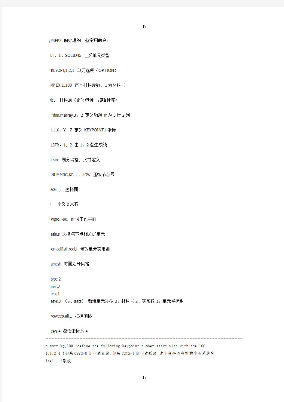
/PREP7 前处理的一些常用命令:
ET,1,SOLID45 定义单元类型
KEYOPT,1,2,1 单元选项(OPTION)
MP,EX,1,100 定义材料参数,1为材料号
tb,材料表(定义塑性、超弹性等)
*dim,rr,array,3,2 定义数组rr为3行2列
k,1,X,Y,Z 定义KEYPOINT1坐标
LSTR,1,2 由1、2点生成线
lesize 划分网格,尺寸定义
NUMMRG,KP, , , ,LOW 压缩节点号
asel ,选择面
r,定义实常数
wpro,,-90, 旋转工作平面
esln,s 选择与节点相关的单元
emodif,all,real,i 修改单元实常数
amesh 对面划分网格
type,2
mat,2
real,1
esys,0 (或aatt)激活单元类型2,材料号2,实常数1,单元坐标系
vsweep,all,,, 扫掠网格
csys,4 激活坐标系4
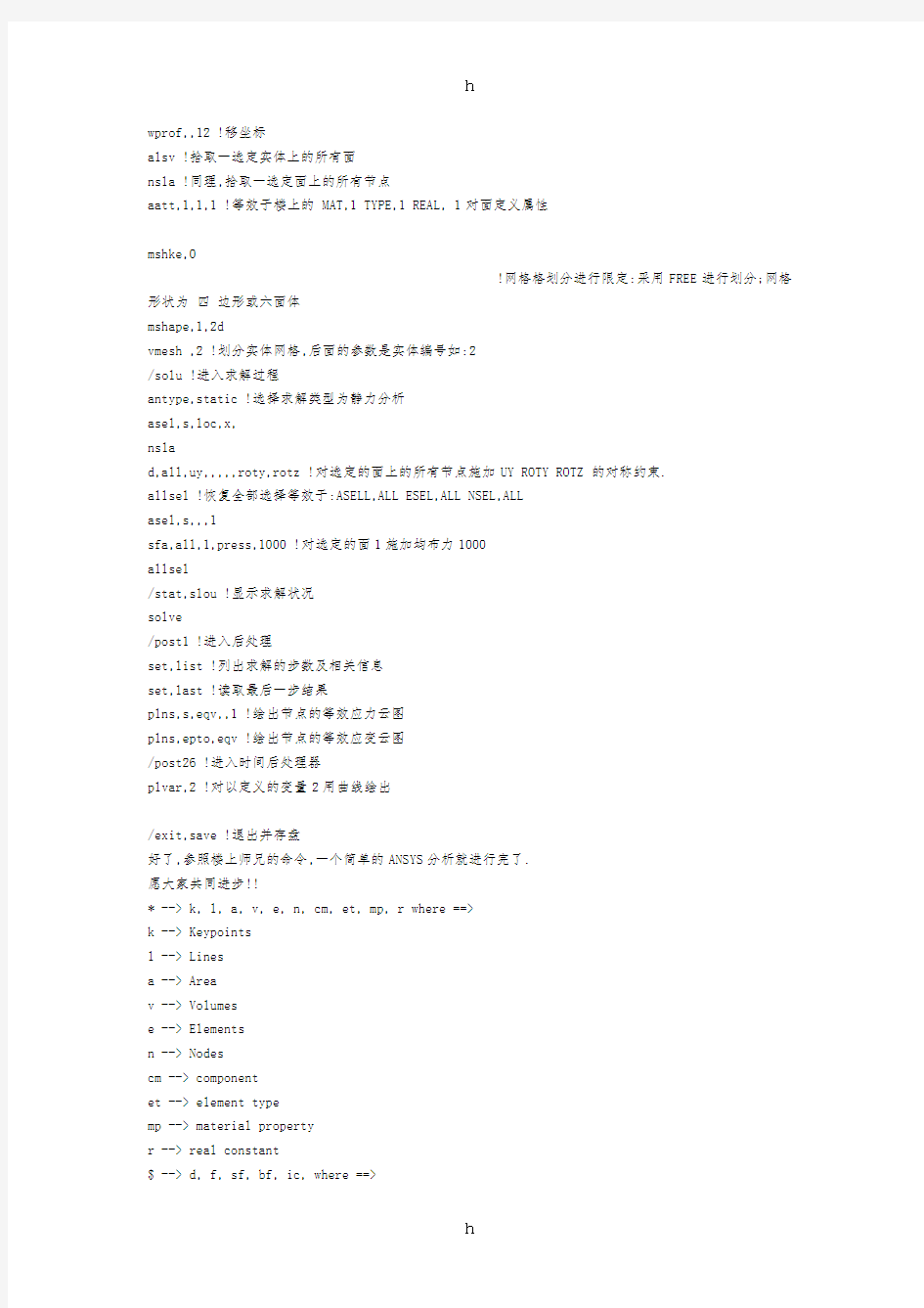
------------------------------------------------------------------------------------------------------------------------------- numstr,kp,100 !define the following keypoint number start with with the 100
l,1,2,4 !如果CSYS=0则生成直线,如果CSYS=1则生成弧线,这个命令与当前的坐标系统有
lsel , !取线
wprof,,12 !移坐标
alsv !拾取一选定实体上的所有面
nsla !同理,拾取一选定面上的所有节点
aatt,1,1,1 !等效于楼上的 MAT,1 TYPE,1 REAL, 1对面定义属性
mshke,0
!网格格划分进行限定:采用FREE进行划分;网格形状为四边形或六面体
mshape,1,2d
vmesh ,2 !划分实体网格,后面的参数是实体编号如:2
/solu !进入求解过程
antype,static !选择求解类型为静力分析
asel,s,loc,x,
nsla
d,all,uy,,,,,roty,rotz !对选定的面上的所有节点施加UY ROTY ROTZ 的对称约束.
allsel !恢复全部选择等效于:ASELL,ALL ESEL,ALL NSEL,ALL
asel,s,,,1
sfa,all,1,press,1000 !对选定的面1施加均布力1000
allsel
/stat,slou !显示求解状况
solve
/post1 !进入后处理
set,list !列出求解的步数及相关信息
set,last !读取最后一步结果
plns,s,eqv,,1 !绘出节点的等效应力云图
plns,epto,eqv !绘出节点的等效应变云图
/post26 !进入时间后处理器
plvar,2 !对以定义的变量2用曲线绘出
/exit,save !退出并存盘
好了,参照楼上师兄的命令,一个简单的ANSYS分析就进行完了.
愿大家共同进步!!
* --> k, l, a, v, e, n, cm, et, mp, r where ==>
k --> Keypoints
l --> Lines
a --> Area
v --> Volumes
e --> Elements
n --> Nodes
cm --> component
et --> element type
mp --> material property
r --> real constant
$ --> d, f, sf, bf, ic, where ==>
d --> DOF constraint (ux... in Structural, Temp in thermal,
f --> Force Load ( Heat in thermal)
sf --> Surface load on nodes
bf --> Body Force on Nodes
$* --> dk --> DOF constraints on KP (Vx,Vy,Pres... in CFD)
dl --> DOF constraints on Lines
da --> DOF constraints on Areas
fk --> Force on Keypoints
sfl --> Surface load on Lines
sfa --> Surface load on Areas
sfe --> Surface load on element faces
bfk --> Body Force on Keypoints
bfl --> Body Force on Lines
bfa --> Body Force on Area
bfv --> Body Force on Volumes
bfe --> Body Force on Elements
ic --> Initial Conditions ",
asba,p --> Subtract Area from Area
asbl,p --> Divide Area by line
vsba,p --> Divide volume by Area
lsbw,p --> Divide line by Workplane
vsbw,p --> Divide volume by Workplane
asbw,p --> Divide area by Workplane
vsbv,p --> subtract Volume by another volume
vdrag,p --> Drag areas along a line to create a new volume
adrag,p --> Drag line along a line to create a new area
ldrag,p --> Drag KP along a line to create a new line
k,p ---> Allows user to pick KP in the Workplane
l,p ---> Create lines from existing KP
ak,p ---> Create area from KP
al,p ---> Create area from lines
v,p ---> Create Volume from KP
va,p ---> Create Volume from Areas
e,p ---> Create Elem from existing nodes
en,p ---> Create Elem from nodes
D,p --> To apply DOF on nodes
DK,p --> To apply DOF on Keypoints
DL,p --> Apply DOF on Lines
DA,p --> Apply DOF on Areas ( symmetry or Anti-symmetry will be prompted) ****************
16b. FORCE Loading:
COMMAND SYNTAX : $*,p
See the valid combinations below:
f,p --> Forces on nodes
fk,p --> Force on Keypoints
(fa,p or FV,p or FL,p ----> Since force cannot be applied on Lines or Area & volumes... this command does not exist.)
sf,p --> Surface Load on a set of Nodes
sfl,p --> Surface Load on Lines
sfa,p --> Surface Load on Area
sfe,p --> Surface Load on Element
(SFk,p and SFV,p do not exist since pressure cannot be applied on a single Kp and neither can it be applied on a volume)
****************
16d. BodyForce Load: COMMAND SYNTAX : bf*,p
See the valid combinations below:
bf,p --> Bodyforce Load on a set of Nodes
bfk,p --> Bodyforce Load on KP
bfl,p --> Bodyforce Load on Lines
bfa,p --> Bodyforce Load on Areas
bfv,p --> Bodyforce Load on Volumes
bfe,p --> Bodyforce Load on E
--------------------------------------------------------------------------------------------------------
ANSYS具有混合网格剖分的功能。例如两个粘在一起的面,可以对一个面进行三角形划分,再对另一个面进行四边形划分。过程见下列命令:
/prep7
et,1,42
rect,,1,,1
rect,1,2,,1
aglue,all
mshape,0,2d
amesh,1
mshape,1,2d
amesh,3
FINISH
/CLEAR
/Title, Cross-Sectional Results of a Simple Cantilever Beam
/PREP7
! All dims in mm
Width = 60
Height = 40
Length = 400
BLC4,0,0,Width,Height,Length ! Creates a rectangle
/ANGLE, 1 ,60.000000,YS,1 ! Rotates the display
/REPLOT,FAST ! Fast redisplay
ET,1,SOLID45 ! Element type
MP,EX,1,200000 ! Young's Modulus
MP,PRXY,1,0.3 ! Poisson's ratio
esize,20 ! Element size
vmesh,all ! Mesh the volume
FINISH
/SOLU ! Enter solution mode
ANTYPE,0 ! Static analysis
ASEL,S,LOC,Z,0 ! Area select at z=0
DA,All,ALL,0 ! Constrain the area
ASEL,ALL ! Reselect all areas
KSEL,S,LOC,Z,Length ! Select certain keypoint
KSEL,R,LOC,Y,Height
KSEL,R,LOC,X,Width
FK,All,FY,-2500 ! Force on keypoint
KSEL,ALL ! Reselect all keypoints
SOLVE ! Solve
FINISH
/POST1 ! Enter post processor
PLNSOL,U,SUM,0,1 ! Plot deflection
WPOFFS,Width/2,0,0 ! Offset the working plane for cross-section view WPROTA,0,0,90 ! Rotate working plane
/CPLANE,1 ! Cutting plane defined to use the WP
/TYPE,1,8 ! QSLICE display
WPCSYS,-1,0 ! Deflines working plane location
WPOFFS,0,0,1/16*Length ! Offset the working plane
/CPLANE,1 ! Cutting plane defined to use the WP
/TYPE,1,5 ! Use the capped hidden display
PLNSOL,S,EQV,0,1 ! Plot equivalent stress
!Animation
ANCUT,43,0.1,5,0.05,0,0.1,7,14,2 ! Animate the slices
1.2 设材料线弹性、非线性特性
u mp,lab, mat, co, c1,…….c4 定义材料号及特性
lab: 待定义的特性项目(ex,alpx,reft,prxy,nuxy,gxy,mu,dens)ex: 弹性模量
nuxy: 小泊松比
alpx: 热膨胀系数
reft: 参考温度
reft: 参考温度
prxy: 主泊松比
gxy: 剪切模量
mu: 摩擦系数
dens: 质量密度
mat: 材料编号(缺省为当前材料号)
co: 材料特性值,或材料之特性,温度曲线中的常数项
c1-c4: 材料的特性-温度曲线中1次项,2次项,3次项,4次项的系数
u Tb, lab, mat, ntemp,npts,tbopt,eosopt 定义非线性材料特性表
Lab: 材料特性表之种类
Bkin: 双线性随动强化
Biso: 双线性等向强化
Mkin: 多线性随动强化(最多5个点)
Miso: 多线性等向强化(最多100个点)
Dp: dp模型
Mat: 材料号
Ntemp: 数据的温度数
对于bkin: ntemp缺省为6
miso: ntemp缺省为1,最多20
biso: ntemp缺省为6,最多为6
dp: ntemp, npts, tbopt 全用不上
Npts: 对某一给定温度数据的点数
u TBTEMP,temp,kmod 为材料表定义温度值
temp: 温度值
kmod: 缺省为定义一个新温度值
如果是某一整数,则重新定义材料表中的温度值
注意:此命令一发生,则后面的TBDATA和TBPT均指此温度,应该按升序
若Kmod为crit, 且temp为空,则其后的tbdata数据为solid46,shell99,solid191中所述破坏准则
如果kmod为strain,且temp为空,则其后tbdata数据为mkin中特性。
