AA-V3-I2-Harnessing-Power-of-Ocean-Waves
Harnessing the
Power of Ocean Waves
Engineers use structural and hydrodynamic analysis to ensure wave-powered electrical generation machines produce maximum energy output and operate effectively for decades.
By George Smith, Managing Director, and Tamas Bodai, Analyst Engineer, Green Ocean Energy Ltd, Aberdeen, Scotland
With rising fuel costs and environ-mental concerns, governments around the world are focusing on clean, safe and sustainable alternative energy sources for power generation. One of the most unique and promising of these concepts is harnessing the energy of the earth’s oceans by converting the relentless force of waves into electricity.
The idea has captured the imagi-nation for centuries, but until now the business justification h as not been sufficient to move such projects forward. Significant engineering hurdles must be overcome to develop efficient, reliable and economical wave-powered electrical generation systems that could be deployed on a mass-production basis. Green Ocean Energy is meeting th ese ch allenges with the help of simulation technology from ANSYS: ANSYS AQWA software for h ydrodynamic analysis of th e wave action and ANSYS DesignSpace software for structural analysis.
Th e engineering team uses th is advanced technology in the develop-ment of the Ocean Treader, a floating device designed to be moored five kilometers offsh ore in open ocean water with relatively h igh wave activity. A second device called the Wave Treader mounts on the base of offsh ore structures such as wind
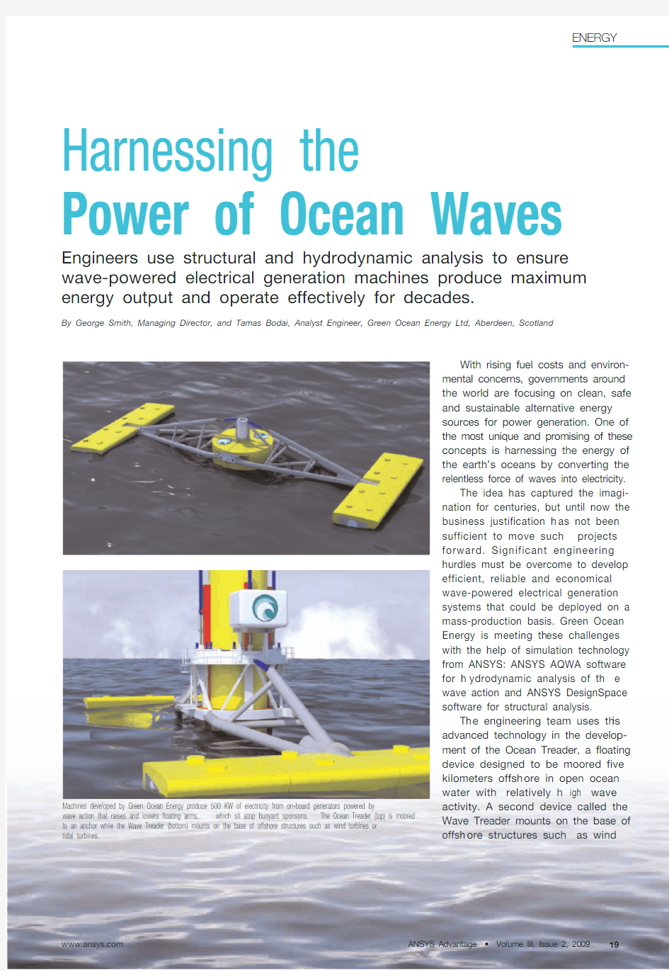
Machines developed by Green Ocean Energy produce 500 KW of electricity from on-board generators powered by wave action that raises and lowers floating arms,which sit atop buoyant sponsons.The Ocean Treader (top) is moored to an anchor while the Wave Treader (bottom) mounts on the base of offshore structures such as wind turbines or tidal turbines.
ANSYS Advantage ? Volume III, Issue 2, https://www.360docs.net/doc/073659279.html, 19
ENERGY
turbines or tidal turbines. Both machines share a similar design, with two 20-meter steel arms floating on a set of sponsons (components th at make the machine buoyant) made of glass-reinforced composite plastic.As wave action moves th e floating arms up and down, hydraulic cylin-ders spin generators th at produce electricity sent back to sh ore via underwater cables. Each machine is designed to produce 500 KW of elec-tricity — enough to power 125 homes — so a farm of 30 such devices would have a rating of 15 MW.
One of the primary challenges the engineers faced was reach ing a balance between structural strength and weigh t restrictions. With an expected 25-year design life, th e machines must withstand rough waters of the North Atlantic, where waves can reach over 9 meters in height in gale-force winds. Conversely, structural members must be lightweight to keep production costs with in budget and
to allow for sufficient floatation.
Software from ANSYS played a key role in meeting these objectives. The design team used the ANSYS AQWA product to determine how the structure would respond to a particular wave action. First, the team created a hydro-dynamic model of the submerged part of the structure based on the geometry of components togeth er with th eir density and inertia. Next, they entered wave data profiles, including wave eigh t and frequency, obtained from empirical measurements in the particular body of water.
From th ese inputs th e ANSYS AQWA application generated a variety of hydrodynamic parameters including:
?Diffraction force accounting for the deformation of waves as they impact the structure ?Froude–Krylov force derived from the pressure field of waves against the structure ?Hydrodynamic damping due to radiation of waves induced by structure motions and the associated energy dissipation
?Added mass of the structure as a result of the surrounding water set in motion by the oscillating body ?Hydrostatic stiffness and buoyancy Hydrodynamic parameters were entered into a proprietary code devel-oped by Green Ocean Energy for computing the kinematic response and resulting power output of the machine.Customized plots of the power output for a range of sizes of the major com-ponents, such as the length of the arms and shape of the sponsons, enabled engineers to determine optimal design parameters for th e major structural members.
Th e structural analysis model to compute stress distribution and defor-mation of components was efficiently achieved through tight integration with Autodesk ?Inventor ?that enabled part geometry to be automatically trans-ferred from CAD to ANSYS Workbench using th e Geometry Interface for
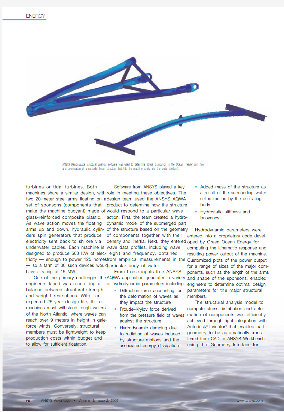
ANSYS DesignSpace structural analysis software was used to determine stress distribution in the Ocean Treader arm (top)and deformation of a spreader beam structure that lifts the machine safely into the water (bottom).
ENERGY
https://www.360docs.net/doc/073659279.html,
ANSYS Advantage ? Volume III, Issue 2, 200920
ANSYS Advantage ? Volume III, Issue 2, 2009ENERGY
https://www.360docs.net/doc/073659279.html, 21
Inventor/MDT. The analytical meshing was greatly simplified through the use of surface-to-surface contact element features that automatically detect con-tact points of touching parts. The use of multiple parts allowed different material properties to be assigned —including the anisotropic nature of the glass-reinforced composite plastic parts.
After an initial simulation cycle was completed using ANSYS DesignSpace software, direct associativity with the CAD system enabled engineers to readily change the design and quickly perform subsequent simulations on the new part geometry without having to re-apply loads or boundary conditions.Green Ocean Energy engineers performed successive iterations to eliminate stress concentrations by adding or trimming material where needed.
ANSYS DesignSpace software was instrumental in minimizing the weight of th e entire structure wh ile h elping to ensure that each part could withstand the range of expected wave forces over time. The technology from ANSYS was crucial in ach ieving th e sensitive balance of mass, moment of inertia and center of gravity so the floating arms would react optimally to wave action.
Currently, engineers are using this procedure to develop Ocean Treader scale-model prototypes — which are undergoing wave-tank trials at this time — and several organizations are expressing strong interest in both the Ocean Treader and Wave Treader. T o fill future orders once tests verify power output and structural integrity, full-scale production models of the machines will be developed using these same tools from ANSYS, with detailed full analysis of final designs to be performed with ANSYS Mechanical software.
In t
is complex development process — in which so many variables must be considered — standard hydro-dynamic calculations alone would be too slow and not detailed enough to provide sufficient insigh t into th e behavior of the machines subjected to severe environmental conditions.Moreover, because prototypes cost over $3 million dollars each and take months to construct, numerous rounds of hardware test-and-redesign cycles are impractical. To meet the rigorous tech nical requirements, product delivery deadlines and business objectives for both th e Ocean Treader and Wave Treader machines,Green Ocean Energy finds the virtual prototyping capabilities of th e advanced tools from ANSYS a critical element in getting th e product to market in a cost-effective and timely manner. s
ANSYS AQWA hydrodynamic software determines how the Wave Treader reacts to wave action by computing hydrodynamic parameters such as diffraction,Froude–Krylov force,radiation damping and added mass.
5.04.0
3.02.01.00.0Frequency (radians/sec)
Dim 2 = -90 deg - Diffraction force - heave(z)
Y*10
+5
N e w t o n s /m
5.04.03.0
2.01.00.00.4
0.6
0.8
1.0
1.2
1.4
1.6
1.8
2.0
Frequency (radians/sec)
Dim 1 = -180 deg - Radiation damping heave(z) - heave(z)
Y*10+5
K g /s
0.4
0.6
0.8
1.0
1.2
1.4
1.6
1.8
2.0
Frequency (radians/sec)
Dim 2 = -90 deg - Froude–Krylov force - heave(z)
Y*10
+6
N e w t o n s /m
4.84.44.03.63.22.82.42.01.61.20.4
0.60.8 1.0 1.2 1.4 1.6 1.8 2.0
Frequency (radians/sec)
Dim 1 = -180 deg - Added mass heave(z) - heave(z)
Y*10
+5
K i l o g r a m s