0A-Transforming-Metal-Nanocomposite-with-Large-Elastic-Strain--Low-Modulus--and-High-Strength
initially aligned with this direction emitted pure circularly polarized photons and remained in-variant under scattering.Their superpositions,on the other hand,became entangled with the scat-tered photon polarization.States that are invariant under coupling to the environment are of interest,not only because of their importance in the quan-tum measurement process but also because of their potential use for quantum control purposes.Invariant states can span decoherence-free sub-spaces in which quantum information can be protected (21).It would be therefore interesting to search for multi-spin states that are invariant under photon scattering,and detection,by using larger arrays of trapped ions.
References and Notes
1.W.H.Zurek,Rev.Mod.Phys.75,715(2003).
2.This mechanism is different than the process of
ein-selection in decoherence theory,in which the mutual interaction between a quantum system,a measurement
apparatus,and their environment results in the emergence of a preferred basis (1).
3.C.J.Myatt et al .,Nature 403,269(2000).
4.M.Brune et al .,Phys.Rev.Lett.77,4887(1996).
5.M.S.Chapman et al .,Phys.Rev.Lett.75,3783(1995).
6.M.Mei,M.Weitz,Phys.Rev.Lett.86,559(2001).
7.D.A.Kokorowski,A.D.Cronin,T.D.Roberts,D.E.Pritchard,Phys.Rev.Lett.86,2191(2001).
8.R.Ozeri et al .,Phys.Rev.Lett.95,030403(2005).
9.H.Uys et al .,Phys.Rev.Lett.105,200401(2010).10.N.Akerman,S.Kotler,Y.Glickman,R.Ozeri,Phys.Rev.Lett.109,103601(2012).
11.D.B.Hume,T.Rosenband,D.J.Wineland,Phys.Rev.Lett.99,120502(2007).
12.A.H.Myerson et al .,Phys.Rev.Lett.100,200502(2008).13.A.Keselman,Y.Glickman,N.Akerman,S.Kotler,R.Ozeri,New J.Phys.13,073027(2011).
14.B.B.Blinov,D.L.Moehring,L.M.Duan,C.Monroe,Nature 428,153(2004).
15.J.Volz et al .,Phys.Rev.Lett.96,030404(2006).16.
N.Akerman,S.Kotler,Y.Glickman,A.Keselman,R.Ozeri,App.Phys.B ,10.1007/s00340-011-4807-6(2011).
17.
Materials and methods are available as supplementary materials on Science Online.
18.Cohen-Tannoudji,Claude and Diu,Bernard and Laloe,
Frank,Quantum Mechanics (Wiley-Interscience 2006),Vol.2,p.1048.
19.M.A.Nielsen,I.L.Chuang,Quantum Computation and
Quantum Information (Cambridge Univ.Press,Cambridge,2000).
20.M.B.Plenio,S.Virmani,https://www.360docs.net/doc/1e99630.html,put.7,
1(2007).
21.D.A.Lidar,I.L.Chuang,K.B.Whaly,Phys.Rev.Lett.81,
2594(1998).Acknowledgments:Y.G.and S.K.have equally contributed to this work.We thank N.Davidsson and D.Stamper-Kurn for useful comments on the manuscript.We gratefully
acknowledge the support by the Israeli Science Foundation,the Minerva Foundation,the German-Israeli Foundation for scientific research,the Crown Photonics Center,and M.Kushner Schnur,Mexico.
Supplementary Materials
https://www.360docs.net/doc/1e99630.html,/cgi/content/full/339/6124/1187/DC1Materials and Methods Figs.S1to S4
3September 2012;accepted 2January 201310.1126/science.1229650
A Transforming Metal Nanocomposite with Large Elastic Strain,Low Modulus,and High Strength
Shijie Hao,1Lishan Cui,1*Daqiang Jiang,1Xiaodong Han,2*Yang Ren,3*Jiang Jiang,1
Yinong Liu,4Zhenyang Liu,1Shengcheng Mao,2Yandong Wang,5Yan Li,6Xiaobing Ren,7,8Xiangdong Ding,7Shan Wang,1Cun Yu,1Xiaobin Shi,1Minshu Du,1Feng Yang,1Yanjun Zheng,1Ze Zhang,2,9Xiaodong Li,10Dennis E.Brown,11Ju Li 7,12*
Freestanding nanowires have ultrahigh elastic strain limits (4to 7%)and yield strengths,
but exploiting their intrinsic mechanical properties in bulk composites has proven to be difficult.We exploited the intrinsic mechanical properties of nanowires in a phase-transforming matrix
based on the concept of elastic and transformation strain matching.By engineering the microstructure and residual stress to couple the true elasticity of Nb nanowires with the pseudoelasticity of a NiTi shape-memory alloy,we developed an in situ composite that possesses a large quasi-linear
elastic strain of over 6%,a low Young ’s modulus of ~28gigapascals,and a high yield strength of ~1.65gigapascals.Our elastic strain-matching approach allows the exceptional mechanical properties of nanowires to be exploited in bulk materials.I
t is challenging to develop bulk materials that exhibit a large elastic strain,a low Young ’s modulus,and a high strength because of the intrinsic trade-off relationships among these prop-erties (1,2).A low Y oung ’s modulus in a single-phase material usually means weak interatomic bonding and thus low strength.Because of the initiation of dislocation activity and/or early fail-ure caused by structural flaws,the elastic strain of bulk metals is usually limited to less than 1%.Because freestanding nanowires have ultrahigh elastic strain limits (4to 7%)and yield strengths (3–9),it is expected that composites made with nanowires will have exceptional mechanical prop-erties.However,the results obtained so far have been disappointing (10),primarily because the in-trinsic mechanical properties of nanowires have not been successfully exploited in bulk composites (10–12).A typical example is the Nb nanowire –Cu matrix composite,in which the nanowires are
well dispersed and well aligned,with strong inter-facial bonding.The elastic strain limit achieved in the Nb nanowires in this type of composite is only ~1.5%(13,14),far below what may be ex-pected of freestanding nanowires (3–9).
To optimize the retention of nanowire prop-erties in a composite,we hypothesize that the matrix should not deform via sharp microscopic defects such as cracks or dislocations but rather should be rubbery or gluelike,which suggests the use of a shape-memory alloy (SMA)as the matrix.There are two main differences between an SMA matrix and a conventional,plastically de-forming metal matrix.First,macroscopically,SMA supports a large pseudoelastic strain of ~7%by stress-induced martensitic transformation (SIMT)(15,16),which is a strain magnitude comparable to nanowire elasticity (3–9).Use of an SMA as the matrix allows one to match the high pseudo-elasticity of the SMA with the high elasticity of
nanowires,as illustrated in Fig.1A.Second,SIMT and dislocation slip are fundamentally different processes at the atomic scale.Whereas the inelastic shear strain between two adjacent atomic planes approaches 100%after dislocation slip (17),the atomic-level inelastic or transformation strain is ~10%after SIMT in typical SMAs such as NiTi (16).Therefore,inelastic strain incompatibilities (which must be compensated for by the elastic strain field to maintain cohesion)are much milder at the SMA-nanowire interface than at typical dislocation –piled-up interfaces.
To verify this hypothesis,we selected Nb nanowires to be combined with a NiTi SMA.The NiTi-Nb system with ~20atomic %Nb un-dergoes eutectic solidification into a microstruc-ture consisting of fine Nb lamellae (18),which can be converted into Nb nanowires through se-vere plastic deformation.In this study,an ingot with a composition of Ni 41Ti 39Nb 20(atomic %)was prepared by means of vacuum induction
1
State Key Laboratory of Heavy Oil Processing,China Uni-versity of Petroleum,Beijing 102249,China.2Institute of Microstructure and Properties of Advanced Materials,Beijing University of Technology,Beijing 100124,China.3X-ray Sci-ence Division,Argonne National Laboratory,Argonne,IL 60439,USA.4School of Mechanical and Chemical Engi-neering,The University of Western Australia,Crawley,WA 6009,Australia.5State Key Laboratory for Advanced Metals and Materials,University of Science and Technology Beijing,Beijing 100083,China.6School of Materials Science and En-gineering,Beihang University,Beijing 100191,China.7State Key Laboratory for Mechanical Behavior of Materials and Frontier Institute of Science and Technology,Xi ’an Jiaotong University,Xi ’an 710049,China.8Ferroic Physics Group,National Institute for Materials Science,Tsukuba,305-0047Ibaraki,Japan.9State Key Laboratory of Silicon Materials,Zhejiang University,Hangzhou 310058,China.10Department of Mechanical Engineering,Uni-versity of South Carolina,Columbia,SC 29208,USA.11Depart-ment of Physics,Northern Illinois University,De Kalb,IL 60115,USA.12Department of Nuclear Science and Engineering and Department of Materials Science and Engineering,Massachu-setts Institute of Technology,Cambridge,MA 02139,USA.*To whom correspondence should be addressed.E-mail:lishancui63@https://www.360docs.net/doc/1e99630.html, (L.C.);xdhan@https://www.360docs.net/doc/1e99630.html, (X.H.);ren@https://www.360docs.net/doc/1e99630.html, (Y.R.);liju@https://www.360docs.net/doc/1e99630.html, (J.L.)
https://www.360docs.net/doc/1e99630.html, SCIENCE
VOL 339
8MARCH 20131191
REPORTS
o n M a y 5, 2016
h t t p ://s c i e n c e .s c i e n c e m a g .o r g /D o w n l o a d e d f r o m
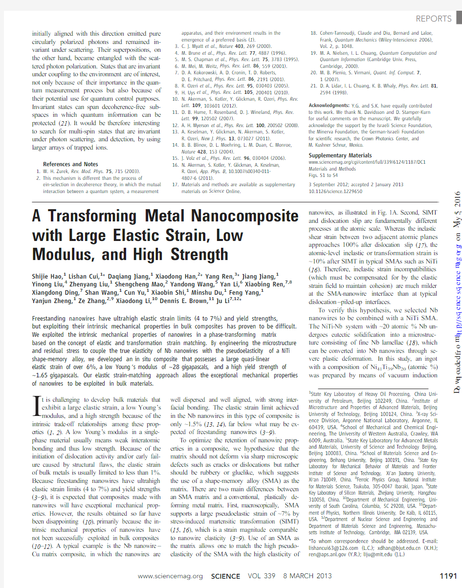
melting (fig.S1).Macroscopic wires of the in situ composite (nanowire in situ composite with SMA,hereinafter referred to as NICSMA)with diameters of 0.3to 1.0mm were subse-quently fabricated by forging,wire-drawing,and annealing (Fig.1B)(19).The typical micro-structure of NICSMA (Fig.1,C to E)consists of Nb nanowires formed in situ with a mean diameter of 60nm,well dispersed and well aligned in the NiTi matrix along the wire axial direction,with well-bonded interfaces.The selected-area electron diffraction (SAED)pattern (Fig.1F)is indexed to body-centered cubic Nb and B2-NiTi phases.The phase components of the composite were fur-ther characterized by high-energy x-ray diffrac-tion (HE-XRD)(fig.S2)and energy-dispersive x-ray spectroscopic analysis (fig.S3).Both SAED and HE-XRD demonstrate that the Nb nanowires are well oriented with its [110]direction parallel to the wire axial direction.Figure 1,G and H,shows the morphologies of freestanding Nb nanowires obtained by removing the NiTi matrix via elec-trolytic etching (fig.S4),revealing that the Nb nanowires have lengths ranging from 1to 100m m and a mean aspect ratio exceeding 100.
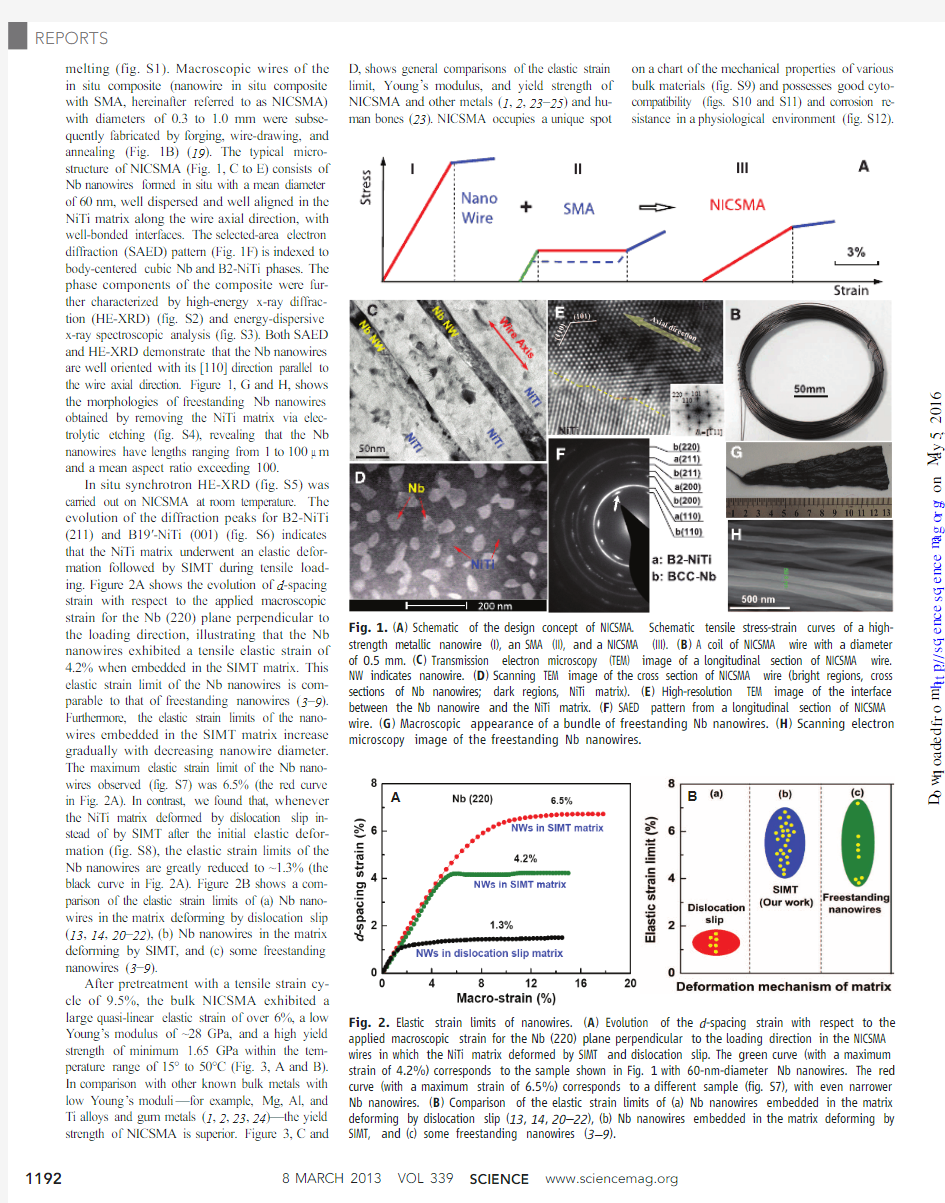
In situ synchrotron HE-XRD (fig.S5)was carried out on NICSMA at room temperature.The evolution of the diffraction peaks for B2-NiTi (211)and B19′-NiTi (001)(fig.S6)indicates that the NiTi matrix underwent an elastic defor-mation followed by SIMT during tensile load-ing.Figure 2A shows the evolution of d -spacing strain with respect to the applied macroscopic strain for the Nb (220)plane perpendicular to the loading direction,illustrating that the Nb nanowires exhibited a tensile elastic strain of 4.2%when embedded in the SIMT matrix.This elastic strain limit of the Nb nanowires is com-parable to that of freestanding nanowires (3–9).Furthermore,the elastic strain limits of the nano-wires embedded in the SIMT matrix increase gradually with decreasing nanowire diameter.The maximum elastic strain limit of the Nb nano-wires observed (fig.S7)was 6.5%(the red curve in Fig.2A).In contrast,we found that,whenever the NiTi matrix deformed by dislocation slip in-stead of by SIMT after the initial elastic defor-mation (fig.S8),the elastic strain limits of the Nb nanowires are greatly reduced to ~1.3%(the black curve in Fig.2A).Figure 2B shows a com-parison of the elastic strain limits of (a)Nb nano-wires in the matrix deforming by dislocation slip (13,14,20–22),(b)Nb nanowires in the matrix deforming by SIMT,and (c)some freestanding nanowires (3–9).
After pretreatment with a tensile strain cy-cle of 9.5%,the bulk NICSMA exhibited a large quasi-linear elastic strain of over 6%,a low Y oung ’s modulus of ~28GPa,and a high yield strength of minimum 1.65GPa within the tem-perature range of 15°to 50°C (Fig.3,A and B).In comparison with other known bulk metals with low Y oung ’s moduli —for example,Mg,Al,and Ti alloys and gum metals (1,2,23,24)—the yield strength of NICSMA is superior.Figure 3,C and
D,shows general comparisons of the elastic strain limit,Young ’s modulus,and yield strength of NICSMA and other metals (1,2,23–25)and hu-man bones (23).NICSMA occupies a unique spot
on a chart of the mechanical properties of various bulk materials (fig.S9)and possesses good cyto-compatibility (figs.S10and S11)and corrosion re-sistance in a physiological environment (fig.S12).
B
A Fig.2.Elastic strain limits of nanowires.(A )Evolution of the d -spacing strain with respect to the applied macroscopic strain for the Nb (220)plane perpendicular to the loading direction in the NICSMA wires in which the NiTi matrix deformed by SIMT and dislocation slip.The green curve (with a maximum strain of 4.2%)corresponds to the sample shown in Fig.1with 60-nm-diameter Nb nanowires.The red curve (with a maximum strain of 6.5%)corresponds to a different sample (fig.S7),with even narrower Nb nanowires.(
B )Comparison of the elastic strain limits of (a)Nb nanowires embedded in the matrix deforming by dislocation slip (13,14,20–22),(b)Nb nanowires embedded in the matrix deforming by SIMT,and (c)some freestanding nanowires (3–9
).
Fig.1.(A )Schematic of the design concept of NICSMA.Schematic tensile stress-strain curves of a high-strength metallic nanowire (I),an SMA (II),and a NICSMA (III).(B )A coil of NICSMA wire with a diameter of 0.5mm.(C )Transmission electron microscopy (TEM)image of a longitudinal section of NICSMA wire.NW indicates nanowire.(D )Scanning TEM image of the cross section of NICSMA wire (bright regions,cross sections of Nb nanowires;dark regions,NiTi matrix).(E )High-resolution TEM image of the interface between the Nb nanowire and the NiTi matrix.(F )SAED pattern from a longitudinal section of NICSMA wire.(G )Macroscopic appearance of a bundle of freestanding Nb nanowires.(H )Scanning electron microscopy image of the freestanding Nb nanowires.
8MARCH 2013
VOL 339
SCIENCE
https://www.360docs.net/doc/1e99630.html,
1192REPORTS
o n M a y 5, 2016
h t t p ://s c i e n c e .s c i e n c e m a g .o r g /D o w n l o a d e d f r o m
Fig.3.Typical macroscopic mechanical properties
of NICSMA.(A)Tensile stress-strain curves of a pre-
treated NICSMA at15°,30°,and50°C.s S,yield
strength;E,Young’s modulus;e e,elastic strain limit.
(B)Cyclic tensile stress-strain curves of a pretreated
NICSMA at room temperature.(C)Comparison of
the yield strengths and elastic strain limits of dif-
ferent materials.(D)Comparison of the yield strengths
and Young’s moduli of different materials.
A B
C
D
A
E
B
C D
Fig.4.Microscopic responses of NICSMA revealed by in situ synchrotron
HE-XRD.(A)Evolution of the d-spacing strain for Nb(220)and B2-NiTi
(211)planes perpendicular to the loading direction during the pretreat-
ment.(Inset)The macroscopic stress-strain curve of the pretreatment.(B)
Evolution of the diffraction peaks of Nb(220),B2-NiTi(211),and B19′-NiTi
(001)during the pretreatment.(C)Evolution of the d-spacing strain for Nb
(220)plane perpendicular to the loading direction during the subsequent
tensile cycle.(Inset)The cyclic stress-strain curve.(D)Evolution of the rela-
tive intensity of the B19′-NiTi(001)diffraction peak during the subsequent
tensile cycle.The relative intensity is defined as the ratio of the integrated
area of the B19′-NiTi(001)diffraction peak at a given applied strain to
that of the B19′-NiTi(001)diffraction peak at the maximum applied strain.
(E)Evolution of the diffraction peaks of Nb(220),B2-NiTi(211),and B19′-
NiTi(001)during the subsequent tensile cycle.The B2-versus-B19′peak
intensity changes continuously,indicating continuous SIMT throughout the
tensile loading.
https://www.360docs.net/doc/1e99630.html, SCIENCE VOL3398MARCH20131193
REPORTS
o
n
M
a
y
5
,
2
1
6
h
t
t
p
:
/
/
s
c
i
e
n
c
e
.
s
c
i
e
n
c
e
m
a
g
.
o
r
g
/
D
o
w
n
l
o
a
d
e
d
f
r
o
m
In situ synchrotron HE-XRD was used to characterize the deformation and phase transfor-mation evolutions of the Nb nanowires and the NiTi matrix,during the pretreatment (Fig.4A,inset)and the subsequent tensile cycle (Fig.4C,inset).After the pretreatment,the Nb nanowires sustained an elastic compressive strain of –1.4%(point D),whereas the NiTi matrix sustained an elastic tensile strain of 1%(point E)(Fig.4A).There is also some retained B19′phase in the matrix (Fig.4B).These results can be understood as follows.Upon removal of the pretreatment load,the plastically deformed Nb nanowires (A to B in Fig.4A)hindered the recovery of the NiTi matrix because of the B19′→B2transfor-mation (15,16),which caused large residual strains in the nanowires and the SMA with some retained B19′phase.This demonstrates that strong coupling between the nanowires and the matrix took place during the pretreatment.In the subse-quent tensile cycle (Fig.4C),the elastic strain achieved in the Nb nanowires was up to 5.6%(A to B),consisting of the preexisting elastic compressive strain of –1.4%(O to B)and an elastic tensile strain of 4.2%(O to A).The NiTi matrix went through continuous SIMT through-out the tensile loading and exhibited an ultralow tangential effective modulus (Fig.4,D and E)rather than undergoing an initial elastic defor-mation followed by an abrupt SIMT transition,as would occur in a monolithic SMA (16).The continuous SIMT can be ascribed to the contri-bution of the preexisting internal tensile stress and the retained B19′phase in the matrix.Upon unloading,the NiTi matrix underwent a reverse transformation from the stress-induced martens-ite to the parent phase (Fig.4,D and E),in-troducing a small hysteresis in the stress-strain curve resulting from energy dissipation during the process.The experimental evidence presented above demonstrates that the Nb nanowires ex-perienced an ultrawide elastic strain of 4.2%–(–1.4%)= 5.6%,which closely matches the phase transformation strain of ~7%of NiTi.This matching of elastic and transformation strains results in the extraordinary properties of NICSMA.
References and Notes
1.M.F.Ashby,Materials Selection in Mechanical Design (Butterworth-Heinemann,Burlington,VT,2005).
2.T.Saito et al .,Science 300,464(2003).
3.E.W.Wong,P.E.Sheehan,C.M.Lieber,Science 277,1971(1997).
4.T.Zhu,J.Li,Prog.Mater.Sci.55,710(2010).
5.Y.Yue,P.Liu,Z.Zhang,X.Han,E.Ma,Nano Lett.11,3151(2011).
6.G.Richter et al .,Nano Lett.9,3048(2009).
7.L.Tian et al .,Nat Commun.3,609(2012).
8.K.Koziol et al .,Science 318,1892(2007).
9.D.A.Walters et al .,Appl.Phys.Lett.74,3803(1999).10.Y.Dzenis,Science 319,419(2008).
11.P.Podsiadlo et al .,Science 318,80(2007).
12.J.N.Coleman,U.Khan,Y.K.Gun'ko,Adv.Mater.18,
689(2006).
13.L.Thilly et al .,Acta Mater.57,3157(2009).14.V.Vidal et al .,Scr.Mater.60,171(2009).
15.K.Otsuka,C.M.Wayman,Eds.,Shape Memory Materials
(Cambridge Univ.Press,Cambridge,1998).
16.K.Otsuka,X.Ren,Prog.Mater.Sci.50,511(2005).17.S.Ogata,J.Li,S.Yip,Science 298,807(2002).
18.M.Piao,S.Miyazaki,K.Otsuka,Mater.Trans.Jpn.Inst.
Met.33,337(1992).
19.See supplementary materials on Science Online.20.C.C.Ayd ?ner,D.W.Brown,N.A.Mara,J.Almer,
A.Misra,Appl.Phys.Lett.94,031906(2009).
21.L.Thilly et al .,Appl.Phys.Lett.88,191906(2006).22.C.Scheuerlein,U.Stuhr,L.Thilly,Appl.Phys.Lett.91,
042503(2007).
23.M.Niinomi,M.Nakai,Int.J.Biomater.2011,1(2011).24.M.Niinomi,Metall.Mater.Trans.A Phys.Metall.Mater.
Sci.33,477(2002).
25.D.C.Hofmann et al .,Nature 451,1085(2008).Acknowledgments:We thank G.H.Wu,H.B.Xu,and Y.F.Zheng for valuable discussions on the deformation mechanism of NICSMA.This work is supported by the key program project of National Natural Science Foundation of China (NSFC)(51231008),the National 973programs of China (2012CB619400and 2009CB623700),and the
NSFC (51071175,51001119,50831001,and 10825419).J.L.also acknowledges support by NSF DMR-1008104and DMR-1120901.X.D.H.acknowledges support by the Beijing High-level Talents (PHR20100503),the Beijing PXM201101420409000053,and Beijing 211project.
D.E.B.acknowledges support by the Institute for NanoScience,Engineering,and Technology (INSET)of Northern Illinois
https://www.360docs.net/doc/1e99630.html,e of the Advanced Photon Source was supported by the U.S.Department of Energy,Office of Science,under contract no.DE-AC02-06CH11357.
Supplementary Materials
https://www.360docs.net/doc/1e99630.html,/cgi/content/full/339/6124/1191/DC1Materials and Methods Figs.S1to S12References (26–30)
9August 2012;accepted 10January 201310.1126/science.1228602
Terrestrial Accretion Under Oxidizing Conditions
Julien Siebert,1*James Badro,2Daniele Antonangeli,1Frederick J.Ryerson 2,3
The abundance of siderophile elements in the mantle preserves the signature of core formation.
On the basis of partitioning experiments at high pressure (35to 74gigapascals)and high temperature (3100to 4400kelvin),we demonstrate that depletions of slightly siderophile elements (vanadium and chromium),as well as moderately siderophile elements (nickel and cobalt),can be produced by core formation under more oxidizing conditions than previously proposed.Enhanced solubility of oxygen in the metal perturbs the metal-silicate partitioning of vanadium and chromium,precluding extrapolation of previous results.We propose that Earth accreted from materials as oxidized as ordinary or carbonaceous chondrites.Transfer of oxygen from the mantle to the core provides a mechanism to reduce the initial magma ocean redox state to that of the present-day mantle,reconciling the observed mantle
vanadium and chromium concentrations with geophysical constraints on light elements in the core.T
he depletion of siderophile (i.e.,“iron-loving ”)elements in Earth ’s mantle relative to chondrites can constrain the redox state of accreting materials during terrestrial accretion and core differentiation (1–4).For example,metal-silicate partitioning experiments at atmospher-ic pressure indicate that the observed depletion of slightly siderophile elements (SSEs)such as V and Cr can only be produced at conditions more reducing than those required to account for the abundance of moderately siderophile elements (such as Ni,Co,and W)or highly siderophile ele-ments (5).Using metal-silicate partition coefficients obtained at pressures up to 25GPa,homogeneous accretion models posit that metal-silicate equilib-rium took place at the base of a deep terrestrial magma ocean at a single oxygen fugacity (f O 2)(6–8).However,the pressure-temperature (P -T )
conditions required to produce the observed de-pletions for V and Cr (at the present-day f O 2)require temperatures that greatly exceed that of the mantle liquidus (2,4,9,10).Such condi-tions are physically inconsistent with the magma ocean hypothesis,where the P -T conditions at the base of a magma ocean necessarily lie be-tween the mantle solidus and liquidus,thereby creating a rheological boundary that enables the metal to pond and equilibrate with the silicate melt.To satisfy this rheological constraint and SSE abundance patterns,recent models of core for-mation constrain metal-silicate equilibration to the P -T conditions of the peridotite liquidus and invoke early accretion of highly reduced materials with a FeO-poor silicate component (2,4,10,11).These initially low f O 2conditions (~IW-4,cor-responding to 4log f O 2units below the iron-wüstite buffer)enhance the siderophile character of the SSEs at the relevant P -T conditions.Subsequent,gradual oxidation of the mantle to ~IW-2over the course of core formation is re-quired to account for moderately siderophile ele-ment abundances and,most important,to reach the current mantle FeO content [8weight percent (wt %)FeO in silicate].Under reducing con-ditions,silicon is likely to be the only light ele-ment entering the core in large amounts (10–12).This scenario relies on extensive pressure and temperature extrapolation of SSE partitioning data,as existing results are restricted to rela-
1
Institut de Minéralogie et de Physique des Milieux Condensés,UniversitéPierre et Marie Curie,UMR CNRS 7590,Institut de Physique du Globe de Paris,75005Paris,France.2Institut de Physique du Globe de Paris,UniversitéParis Diderot,75005Paris,France.3Lawrence Livermore National Laboratory,Livermore,CA 94551,USA.
*To whom correspondence should be addressed.E-mail:julien.siebert@impmc.upmc.fr
8MARCH 2013VOL 339
SCIENCE
https://www.360docs.net/doc/1e99630.html,
1194REPORTS
o n M a y 5, 2016
h t t p ://s c i e n c e .s c i e n c e m a g .o r g /D o w n l o a d e d f r o m
(6124), 1191-1194. [doi: 10.1126/science.1228602]
339Science Xiaodong Li, Dennis E. Brown and Ju Li (March 7, 2013)
Yu, Xiaobin Shi, Minshu Du, Feng Yang, Yanjun Zheng, Ze Zhang,Wang, Yan Li, Xiaobing Ren, Xiangdong Ding, Shan Wang, Cun Yandong Jiang Jiang, Yinong Liu, Zhenyang Liu, Shengcheng Mao, Shijie Hao, Lishan Cui, Daqiang Jiang, Xiaodong Han, Yang Ren,Strain, Low Modulus, and High Strength
A Transforming Metal Nanocomposite with Large Elastic
Editor's Summary
as the matrix material to produce a much better (more elastic) composite.) used a shape memory alloy Zhou (p. 1191; see the Perspective by et al.Hao bonding with the matrix. longer be stretched to the same extent, even when the nanowires are well distributed and show good 4 to 7%. However, when placed inside a metal matrix to form a composite, these nanowires can no deformation occurs. Metal nanowires can be elastically stretched to much higher strains, on the order of Most metals show elastic strain limits well below 1%, beyond which permanent plastic
S-T-R-E-T-C-H Me
This copy is for your personal, non-commercial use only.
Article Tools
https://www.360docs.net/doc/1e99630.html,/content/339/6124/1191article tools:
Visit the online version of this article to access the personalization and Permissions
https://www.360docs.net/doc/1e99630.html,/about/permissions.dtl
Obtain information about reproducing this article: is a registered trademark of AAAS.
Science Advancement of Science; all rights reserved. The title Avenue NW, Washington, DC 20005. Copyright 2016 by the American Association for the
in December, by the American Association for the Advancement of Science, 1200 New York (print ISSN 0036-8075; online ISSN 1095-9203) is published weekly, except the last week Science o n M a y 5, 2016
h t t p ://s c i e n c e .s c i e n c e m a g .o r g /D o w n l o a d e d f r o m