PL-2303中文说明书
Release Date: July, 2002 ds_pl2303_v14
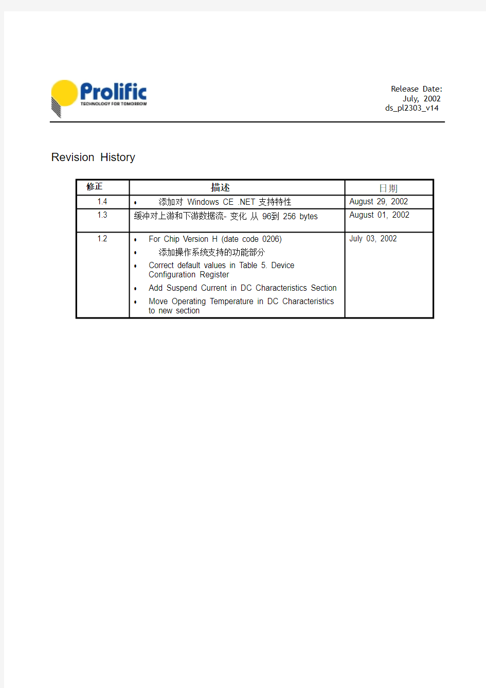
Revision History
发布日期: 七月, 2002年 ds_pl2303_v14
PL-2303 USB 转 Serial RS232 桥接控制器
特性
_ 完全符合 USB 规范:v1.1 和 USB CDC 1.1 _ 支持RS232串行接口
_ 支持自动的握手模式 _ 支持远程唤醒和电源管理 _ 256字节缓冲区每个对上游和下游的数据流 _设备配置支持缺省 ROM 或者外部 EEPROM _ 片上USB 收发器
_ 片上晶体振荡器在12M Hz 运行
_ 支持 Windows 98/SE, ME, 2000, XP , Windows CE3.0, CE .NET, Linux, and Mac OS _ 28 引脚 SOIC 封装
OSC2
28 OSC1
27 26 PLL_TEST
VDD_3V3 17
16DM 15
DP
GND_3V3 18 VDD_PLL LD_MODE GND_PLL GND VDD RESET 1
2 3 12 13 14
11 25 24 23 22 21 20 19 4 5 6 7 8 9 10 TRI_MODE TXD DTR_N RTS_N VDD_232 RXD RI_N GND VDD DSR_N DCD_N CTS_N SHTD_N EE_CLK EE_DATA
SSOP 28 PACKAGE
(TOP VIEW)
Release Date: July, 2002 ds_pl2303_v14
框图
USB Port
Release Date: July, 2002 ds_pl2303_v14
概述
The PL-2303 operates as a bridge between one USB port and one standard RS232 Serial port. The two large on-chip buffers accommodate data flow from two different buses. The USB bulk-type data is adopted for maximum data transfer. Automatic handshake is supported at the Serial port. With these, a much higher baud rate can be achieved compared to the legacy UART controller.
This device is also compliant with USB power management and remote wakeup scheme. Only minimum power is consumed from the host during Suspend. By integrating all the function in a SOIC-28 package, this chip is suitable for cable embedding. Users just simply hook the cable into PC or hub’s USB port, and then they can connect to any RS-232 devices.
引脚功能
Release Date: July, 2002 ds_pl2303_v14
Type: I – 输入信号
O – 输出信号 I/O – 双向信号
P – 电源/接地
支持的数据格式和可编程的波特率发生器
The PL2303 USB-to-RS232 bridge controller supports versatile data formats and has a programmable baud rate generator. The supported data formats are shown on Table 2. The programmable baud rate generator supports baud rates up to 1.2M bps as shown in Table 3.
Release Date: July, 2002 ds_pl2303_v14
External EEPROM and Device Configuration
PL-2303 allows storing the configuration data in an external EEPROM. After reset, the first two bytes of EEPROM are checked. If the value is 067Bh, the EEPROM is valid and the contents of the EEPROM are loaded as the chip’s default parameters. Otherwise, the chip’s default setting is used. The content of EEPROM is shown in Table 4 below.
The Device Configuration Register is used to control some vendor-specific functions. The meaning of each bit in Device Configuration Register is shown in Table 5. Reserved and unused pins always set to the default value.
Release Date: July, 2002 ds_pl2303_v14
Release Date: July, 2002 ds_pl2303_v14
Electrical 特性
*1. RS232 pins RXD_I, RI_I, DSR_I, DCD_I, CTS_I are 5V TTL Schmitt Trigger inputs.
*2. RS232 pins TXD, DTR_N, RTS_N are 3.3V tri-state outputs.
Release Date: July, 2002 ds_pl2303_v14
USB 收发器特性
ohm V
V
C L
: 50pf
时钟特性
封装与尺寸 (28-Pin SSOP)
Release Date: July, 2002 ds_pl2303_v14
Outline Diagram
A I L A
A
0.25
D ET A I L A
1