日立水冷螺杆式冻水机型号资料
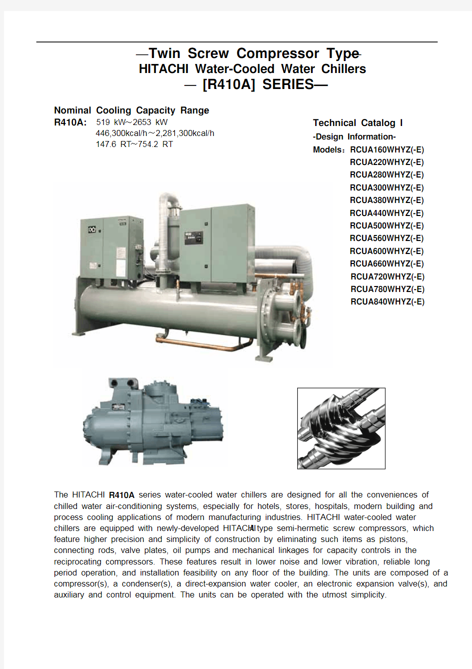

—Twin Screw Compressor Type— HITACHI Water-Cooled Water Chillers
— [R410A] SERIES—
Nominal Cooling Capacity Range: R410A: 519 kW~2653 kW
446,300kcal/h~2,281,300kcal/h 147.6 RT~754.2 RT
Technical Catalog I
-Design InformationModels:RCUA160WHYZ(-E) RCUA220WHYZ(-E) RCUA280WHYZ(-E) RCUA300WHYZ(-E) RCUA380WHYZ(-E) RCUA440WHYZ(-E) RCUA500WHYZ(-E) RCUA560WHYZ(-E) RCUA600WHYZ(-E) RCUA660WHYZ(-E) RCUA720WHYZ(-E) RCUA780WHYZ(-E) RCUA840WHYZ(-E)
The HITACHI R410A series water-cooled water chillers are designed for all the conveniences of chilled water air-conditioning systems, especially for hotels, stores, hospitals, modern building and process cooling applications of modern manufacturing industries. HITACHI water-cooled water chillers are equipped with newly-developed HITACHI A type semi-hermetic screw compressors, which feature higher precision and simplicity of construction by eliminating such items as pistons, connecting rods, valve plates, oil pumps and mechanical linkages for capacity controls in the reciprocating compressors. These features result in lower noise and lower vibration, reliable long period operation, and installation feasibility on any floor of the building. The units are composed of a compressor(s), a condenser(s), a direct-expansion water cooler, an electronic expansion valve(s), and auxiliary and control equipment. The units can be operated with the utmost simplicity.
FEATURES
The Combination of HITACHI Screw Compressor and Microcomputer Inclines HITACHI Water-Cooled Water Chillers to be perfect.
Discharge Gas Outlet Oil Separator Motor for Compressor Slide Valve
Suction Gas Inlet
Bearing
High Efficiency Various Functions
Precise Temperature Control
Micro-processor control for various functions
A micro-processor has been applied to the new models for following various functions. Alarm indication for each cycle by 7-segment Rotating control of compressor starting order Current limitation control Automatic start after instantaneous power failure. Remote /location switch. Communication adapter connecting the unit to BMS (Building Management System) is an optional accessory.
Liquid Crystal Display (Optional)
Big colorful liquid crystal touch panel(optional) Provides English and Chinese display interfaces. Message board function(for shift) Real time Information Return to factory setting Time starting function With RS485 physics connection, communication adapter provides communication to BMS. (Building Management System)
English Interface
Chinese Interface
1
FEATURES
Lower Noise、 Lower Vibration and Reliable Long Period Operation… The Hitachi Screw Water Chiller Can Meet Your Requirements! !
Hitachi’s Semi-Hermetic Screw Compressor
The newly-developed HITACHI semi-hermetic screw compressors feature long life and quiet operation due to simplicity of construction when compared with the conventional reciprocating compressors.
Easy for Maintenance
Equipped with accessibility components such as Pressure Relief
Valve and Oil Sight Glass, easy maintenance is obtained.
A Symmetrical Rotor Profile and Other Features.
This profile of the compressor rotor, five-six (male and female) type, assures excellent efficiency even in high compression ranges, in addition to these uniquely-profile rotors, the following features are incorporated. Use of special bearing, resulting in long life and high reliability Patented capacity control system, enabling simple control system. High precision and high-grade finishing rotors, enabling no oil-cooling system.
Factory-Charged
The refrigeration cycle is charged with refrigerant and sealed under a strict quality control, therefore installation and operation can be performed in a short period of time.
Factory-Wires
Only power wiring and water piping are required in the field.
Most Reliable Protective and Ancillary Components Automatic Capacity Control
An Automatic capacity control mechanism enables the unit to perform economical and energy-saving operation depending on various conditions. Additionally, one(1) independent refrigeration cycles are provided for model RCUA160WHYZ(-E), RCUA220WHYZ(-E), RCUA280WHYZ(-E), RCUA300WHYZ(-E). two(2) independent refrigeration cycles are provided for model RCUA380WHYZ(-E), RCUA440WHYZ(-E), RCUA500WHYZ(-E), RCUA560WHYZ(-E), RCUA600WHYZ(-E). Three(3) independent refrigeration cycles are provided for model RCUA660WHYZ(-E), RCU720WHYZ(-E), RCUA780WHYZ(-E), RCUA840WHYZ(-E). The units are protected against any assumed failure of operation, based on the following components: Electronic Timer for Compressors, Three-Phase Quick Response Overcurrent Relay, Internal Thermostats for Compressor Motors, Freeze Protection Thermistors. Pressure Relief Valve, Oil Sight Glass, Oil Heater, and Reverse-Phase Protection Relays for Compressors.
Timer Counter
This timer counter indicates the operation hour of the screw compressor; therefore, accurate maintenance time can be checked with this timer counter.
Standard Accessories
The following accessories are supplied with the unit:
1. Vibration-Proof Rubber Mats 2. Foundation Bolts The combination of these mats and bolts effectively minimizes noise and vibration, and is coupled with facilitated installation procedures.
The following accessories are chose and bought by customers
1. Communication adapter connecting the unit to BMS (Building Management System) is an optional accessory. ( LONWORKS or RS485 for choosing) 2. Big colorful liquid crystal screen display.( both English and Chinese can be supplied). Please get in touch with HITACHI or HITACHI distributor if required.
2
GENERAL DATA
General Data
S tandard Model Liquid Crystal Display Type kW Nominal Cool ing Capacity kcal/h RT Input Power Condenser Water Flow Rate Chilled Water Flow Ra te Cooling Capacity Control Outer Dimensions Depth Width Height Type Refrigerant Flow Control Number of Ci rcuits Type Compressor Model Quantity Condenser Water Cooler kW m /h m /h — % mm mm mm — — — — — — — — 150 ASCCW-Z 200 ASCCW-Z 1 Shell-and-Tube Type Shell-and-Tube,Dry Expansion Type Three-Phase Over-current Relay High-Pressure Switch Low-Pressure control Oil Heater Internal Thermostat for Compressor Motor Freeze Protection Thermistor Reverse Phase Protection Relay Discharge Gas Thermistor Operation Hour-Meter and Pressure Rel ief Valve. 1×With φ167mm Inner Diameter Companion Flange 1×With φ167mm Inner Diameter Companion Flange 1×With φ167mm Inner Diameter Companion Flange 1×With φ167mm Inner Diameter Companion Flange 3363 1488 2173 1 Module 3082 3478 3507 3903 3850 4246 3895 4291 2 Modules 3507|3082 3903|3478 3507|3507 3903|3903 2×With φ167mm Inner Diameter Companion Flange 2×With φ167mm Inner Diameter Companion Flange 2×With φ167mm Inner Diameter Companion Flange 2×With φ167mm Inner Diameter Companion Flange 1 Semi-Hermetic Screw Type 250 ASCCW-Z 2 50 ASCCW-Z 150|200 ASCCW-Z 2 200|200 ASCCW-Z 100 3018 1285 1900 R410A Electronic Expansion Valve 2
3 3
RCUA160WH RCUA220W RCUA 280WH RCUA300WHYZ RCUA380WHYZ RCUA440WHYZ HYZ YZ YZ RCUA160WH RCUA220W RCUA 280WH RCUA300WHYZ- RCUA380WHYZ- RCUA440WHYZ YZ-E YZ-E E E HYZ-E -E 519 446,300 147.6 101.3 107 89 704 605,500 200.2 137.5 145 121 884 760,400 251.4 172.5 182 152 9 72 835,900 2 76 189.5 2 00 1 67 1223 1,051,900 347.8 238.8 145/107 121/89 1408 1,211, 100 400 275 145/145 121/121
Continuous capacity control 15 0 100 15 7.5 0
3018 2670 1900
Safety Devices
—
Piping Connections for Condenser Piping Connections for Water Cooler
Inlet Outlet Inlet Outlet Depth
— — — — mm mm mm — kg kg
Shipping
Width Height Number
Net weight Shipping Weight
Notes 1.The nominal cooling capacities are based on the GB/T18430.1 Chilled Water Inlet/Outlet Temperature 2.Applicable Power Supplies Main Power Source 3φ 380V 415V 50Hz 50Hz Control Power Supplies 1φ 220V 240V 50Hz 50Hz 22℃ to 37℃ 5℃ to 20℃ 12/7℃ 30/35℃ Condenser Water Inlet/Outlet Temperature 5. The units greater than RCUA380WHYZ(-E)including RCUA 380 WHYZ(-E)consist of two modules or more than two are separately shipped. 6. The unit liquid crystal display differs from the unit with segment code display in electrical box however, both have the same outer dimensions. 7. Communication adapter connecting the unit to BMS Building Management System is an optional accessory, please get in touch with HITACHI or HITACHI distributor if required.
3. Working Range Condenser Water Outlet Temperature Chilled Water Outlet Temperature 4.( ) marked with
is available by selection switch.
3
GENERAL DATA
General Data
Standard Model Liquid Crystal Display Type kW Nominal Cool ing Capacity kcal/h RT Input Power Condenser Water Flow Rate Chilled Water Flow Rate Cooling Capacity Control Outer Dimensions Depth Width Height Type Refrigerant Flow Control Number of Circuits Type Compressor Model Quantity Condenser Water Cooler Safety Devices kW m /h m /h — % mm mm mm — — — — — — — — — 250|200 ASCCW-Z 250|250 AS CCW-Z 2 Shell-and-Tube Type Shell-and-Tube,Dry Expansion Type Three-Phase Over-current Relay High-Pressure Switch Low-Pressure control Oil Heater Internal Thermostat for Compressor Motor Freeze Protection Thermistor Reverse P hase Protection Relay Discharge Gas Thermistor O peration Hour-Meter and P ressure Relief Valve. 2×With φ167mm Inner Diameter Companion Flange 2×With φ167mm Inner Diameter Companion Flange 2×With φ167mm Inner Diameter Companion Flange 2×With φ167mm Inner Diameter Companion Flange 3×Wi th φ16 7mm Inner Diameter Companion Flange 3×Wi th φ16 7mm Inner Diameter Companion Flange 3×Wi th φ16 7mm Inner Diameter Companion Flange 3×Wi th φ16 7mm Inner Diameter Companion Flange 3363 1488 2173 2 Modules 3850|3507 4246|3903 3850|3850 4246|4246 3895|3895 4291|4291 3507 |3507 |3507 3903 |3903 |3903 3 Modul es 3850 |3507 |3507 4246 |3903 |3903 3850 |3850 |3507 4246 |4246 |3903 3850 |3850 |3850 4246 |4246 |4246 2 Semi -Hermetic S crew Type 250|250 AS CCW-Z 200|200|200 ASCCW-Z 250|200|200 ASCCW-Z 3 250|250|200 ASCCW-Z 250|250|250 ASCCW-Z 100 15 7.5 0
3 3
RCUA500W RCUA560WH RCUA600WH RCUA660WH RCUA720WH RCUA780WH RCUA840W YZ HYZ YZ YZ YZ YZ HYZ RCUA500W RCUA560WH RCUA600WH RCUA660WH RCUA720WH RCUA780WH RCUA840W YZ-E HYZ-E YZ-E YZ-E YZ-E YZ-E HY Z-E 1588 1,366,000 451.6 310 182|145 152|121 1768 1,520,800 502.8 345 182|182 152|152 1944 1,671,800 553 379 200|200 167|167 2112 1,816,600 600.6 412.5 145|145|145 121|121|121 2292 1,971,500 651.8 447.5 182|145|145 152|121|121 2473 2,126,400 703 482.5 182|182|145 152|152|121 2653 2,281,3 00 754.2 517.5 182|182|182 152|152|152
Continuous capacity control 100 15 5 0
3018 2670 1900 R410A Electronic Expansion Valve
3018 4055 1900
3
Piping Connections for Condenser Piping Connections for Water Cooler
Inl et Outlet Inl et Outlet Depth
— — — — mm mm mm — kg kg
Shipping
Width Height Number
Net weight Shipping Weight
Notes
1.The nominal cooling capacities are based on the GB/T18430.1 Chilled Water Inlet/Outlet Temperature 2.Applicable Power Supplies Main Power Source 3φ 380V 415V 50Hz 50Hz Control Power Supplies 1φ 220V 240V 50Hz 50Hz 22 5 to 37 to 20 12/7 30/35℃ Condenser Water Inlet/Outlet Temperature
5. The units greater than RCUA380WHYZ(-E)including RCUA 380 WHYZ (-E) consist of two modules or more than two are separately shipped. 6. The unit liquid crystal display differs from the unit with segment code display in electrical box however, both have the same outer dimensions. 7. Communication adapter connecting the unit to BMS Building Management System is an optional accessory, please get in touch with HITACHI or HITACHI distributor if required.
3. Working Range Condenser Water Outlet Temperature Chilled Water Outlet Temperature 4.( ) marked with
is available by selection switch.
4
DIMENSIONAL DATA
For odels:RCUA160/220/280/300WHYZ -E
For models:RCUA380/440/500/560/600WHYZ -E
For models:RCUA660/720/780/840WHYZ -E
-5-
SELECTION DATA
Operation Space
Model RCUA160WHYZ(-E) Dimension(mm) A B C D Mode Dimension(mm) A B C D
D B
C A
RCUA220 WHYZ(-E) RCUA280WHYZ(-E) RCUA300 WHYZ(-E) RCUA380WHYZ(-E) RCUA440WHYZ(-E) 1200 600 1500 600
RCUA560WHYZ(-E) RCUA600WHYZ(-E) RCUA660 WHYZ(-E) RCUA720 WHYZ(-E) RCUA780WHYZ(-E) RCUA840 WHYZ(-E) 1200 600 1500 600
Note: * Operation space of side C depends on connection of field-piping.
RCUA500 WHYZ(-E)
Weight Balance 、Center of Gravity and Operation Weight
Rear Side of Unit Base 1 Center of gravity
B A
3
O: Location of Foundation Bolt
4
2 Front Face of Unit
Model 1 RCUA160 WHYZ(-E) RCUA380WHYZ(-E)-2 RCUA220 WHYZ(-E) RCUA380WHYZ(-E)-1 RCUA440WHYZ(-E)-1,2 RCUA500WHYZ(-E)-2 RCUA660WHYZ(-E)-1,2 , 3 ; RCUA720WHYZ(-E)-2,3 RCUA780WHYZ(-E)-3 RCUA280 WHYZ(-E) RCUA500WHYZ(-E)-1 RCUA560WHYZ(-E)-1,2 RCUA720WHYZ(-E)-1 RCUA780WHYZ(-E)1,2 RCUA840WHYZ(-E)-1,2,3 RCUA300 WHYZ(-E) RCUA600WHYZ(-E)-1,2 927
Weight Distribution (kg) Location 2 3 916 971
4 948
Center of Gravity (mm) Location A B 1500 670
Operation Weight (kg) 3462
981
968
1026
1002
1500
675
4077
1078
1092
1132
1108
1500
680
4410
1091
1106
1141
1117
1480
680
4455
Foundation Bolt and Rubber Mat
Dimensions (mm) Model L1 L2 L3 L4 L5 L6 L7
RCUA160WHYZ(-E) RCUA220WHYZ(-E) RCUA280WHYZ(-E) RCUA300WHYZ(-E) RCUA380WHYZ(-E) RCUA440WHYZ(-E) RCUA500WHYZ(-E) RCUA560WHYZ(-E) RCUA600WHYZ(-E) RCUA660WHYZ(-E) RCUA720WHYZ(-E) RCUA780WHYZ(-E) RCUA840WHYZ(-E)
Rubber Mat (with Holes)
300
58
38
150
100
50
27
6
SELECTION DATA
The Field Piping Connection Fig. for RCUA380~600WHYZ(-E)
Notes:(1) The Piping Connection above-mentioned is suitable for the units of RCUA380~ 600WHYZ(-E) and just for reference. Both cooling water outlet and chilled water outlet need to install a flow rate control valve respectively. (2) Support the water pipes with stay not to give the weight of water pipes directly to the unit, if not, a severe damage may occur due to excessive weight of the piping side, specially while the unit is running.
The Field Piping Connection Fig. for RCUA660~840WHYZ(-E)
Notes:(1) The Piping Connection above-mentioned is suitable for the units of RCUA660~ 840WHYZ(-E) and just for reference. Both cooling water outlet and chilled water outlet need to install a flow rate control valve respectively. (2) Support the water pipes with stay not to give the weight of water pipes directly to the unit ,if not, a severe damage may occur due to excessive weight of the piping side, specially while the unit is running.
7
SELECTION DATA
Selection Example
1.Determination the System Requirements. Calculate the total Load under design conditions. Given conditions: Power Source Frequency 50Hz Cooling Load 1750kW(1,505,000Kcal/h) Condenser Water Inlet Temperature 30℃ Condenser Water Outlet Temperature 35℃ Chilled Water Inlet Temperature 12℃ Chilled Water Outlet Temperature 7℃ Fouling Factor of Water Cooler 0.018 m2℃/kW Fouling Factor of Condenser 0.044 m2℃/kW 2.Select a Matching Model and Read Performance of the Unit Select unit model RCUA560WHYZ(-E) ,according to the conditions mentioned above :condenser water outlet temperature (CDOT) of 35℃ and chilled water outlet temperature (CLOT) of 7℃. 3.Read the Unit Performance of the Model. The compressor Inlet (IPT), cooling capacity (CCAP),Chilled water flow rate (CFR), condenser flow rate (HFR) can directly be determined from the table and the figure. In the case where the data cannot directly be determined from the table, the data can be determined by interpolation. Compressor Input (IPT) 345kW Cooling Capacity(CCAP) 1768kW(1,520, 480Kcal/h) Chilled Water Flow Rate (CFR) 304m3/h Cooled Water Flow Rate (HFR) 363m3/h Condenser Heat Discharge.(HCAP) 2113 kW Cooler Pressure Drop (CPD) 62kPa Condenser Pressure Drop (HPD) 40kPa 4.Correct the Data Flow Rate when the inlet and outlet water temperature difference of the condenser or the water cooler is different from 5℃,please correct the water flow rater of the condenser or water cooler by following formulas.
5℃ Corrected Flow = × Given Temperature Rate Difference (℃) Flow Rate From the Table
Cooling Capacity and Compressor Input When fouling factors are different from 0.018m2. ℃/kW(cooler) and 0.44 m2.℃/kW(condenser) ,the cooling capacity or compressor input will also be different from the value indicated in the cooling capacity table. The correction formulas are as follow:
Corrected Cooling = Correction Factor Capacity
× Indicated in Table
Cooling Capacity
and
Corrected = Correction Compressor Factor Input
× Input indicated
in Table
Compressor
Correction Factor for Cooling Capacity and Compressor Input Regarding Fouling Factor
Fouling Factor m2. ℃/kW Water Cooler 0(0) 0.018 0(0) 0.044 0.086
Cooling Capacity 1.01 1.00 1.01 1.00 0.99
Compressor Input 1.00 1.00 0.99 1.00 1.01
or
Corrected Flow= Water Flow × Factor Rate Flow Rate from the Table
Condenser
8
SELECTION DATA
Pressure Drop Figure of Cooler and Condenser
Model: RCUA***WHYZ(-E) Water Cooler:
1. RCUA160WHYZ(-E)
(Range:160HP-840HP)
RCUA380WHYZ(-E)-2
2. RCUA220WHYZ(-E)
RCUA380WHYZ(-E)-1 RCUA440WHYZ(-E)-1,2 RCUA500WHYZ(-E)-2 RCUA660WHYZ(-E)-1,2,3 RCUA720WHYZ(-E)-2,3 RCUA780WHYZ(-E)-3
3. RCUA280WHYZ(-E)
RCUA300WHYZ(-E) RCUA500WHYZ(-E)-1 RCUA560WHYZ(-E)-1,2 RCUA600WHYZ(-E)-1,2 RCUA720WHYZ(-E)-1 RCUA780WHYZ(-E)-1,2 RCUA840WHYZ(-E)-1,2,3
Condenser
4. RCUA160WHYZ(-E)
RCUA380WHYZ(-E)-2
5. RCUA220WHYZ(-E)
RCUA380WHYZ(-E)-1 RCUA440WHYZ(-E)-1,2 RCUA500WHYZ(-E)-2 RCUA660WHYZ(-E)-1,2,3 RCUA720WHYZ(-E)-2,3 RCUA780WHYZ(-E)-3
6. RCUA280WHYZ(-E)
RCUA300WHYZ(-E) RCUA500WHYZ(-E)-1 RCUA560WHYZ(-E)-1,2 RCUA600WHYZ(-E)-1,2 RCUA720WHYZ(-E)-1 RCUA780WHYZ(-E)-1,2 RCUA840WHYZ(-E)-1,2,3
9
Cooling Capacities
RCUA160WHYZ(-E)
IPT
77.2 77.8 78.5 79.1 79.8 80.4 81.1 82.5 83.1 83.8 84.4 85.1 85.7 86.4 91.2 91.8 92.5 93.2 93.8 94.5 95.1 100.0 100.6 101.3 102.0 102.6 103.3 103.9 103.6 104.3 104.9 105.6 106.2 106.9 107.6
SELECTION DATA
Conversion Multiplier: 1kW = 860kcal/h = 3412Btu/h 1kPa = 0.102mAq
CDOT
CLOT
5 6 7 8 9 10 11 5 6 7 8 9 10 11 5 6 7 8 9 10 11 5 6 7 8 9 10 11 5 6 7 8 9 10 11
RCUA220WHYZ(-E)
HFR
109.6 112.1 114.6 117.1 119.6 122.0 124.5 107.6 110.1 112.6 115.1 117.6 120.1 122.6 104.6 107.1 109.6 112.1 114.6 117.1 119.6 101.6 104.1 106.6 109.1 111.6 114.1 116.6 100.4 102.9 105.4 107.9 110.4 112.8 115.3
CCAP
560 574 588 602 615 629 643 543 557 571 585 599 613 626 517 531 545 559 573 586 600 491 505 519 533 546 560 574 480 494 508 522 535 549 563
CFR
96.3 98.7 101.1 103.5 105.8 108.2 110.6 93.5 95.8 98.2 100.6 103.0 105.3 107.7 89.0 91.3 93.7 96.1 98.5 100.8 103.2 84.5 86.8 89.2 91.6 94.0 96.3 98.7 82.6 85.0 87.3 89.7 92.1 94.5 96.8
CPD
90.0 92.5 95.1 97.7 100.2 102.8 105.4 87.0 89.4 92.0 94.6 97.2 99.6 102.2 82.2 84.7 87.2 89.8 92.3 94.8 97.4 77.5 79.9 82.4 85.0 87.5 90.0 92.5 75.5 78.0 80.4 83.0 85.5 88.1 90.5
HCAP
637 652 666 681 695 710 724 626 640 655 669 684 698 713 608 623 637 652 666 681 695 591 606 620 635 649 663 678 584 598 613 627 642 656 671
HPD
29.2 30.6 32.1 33.7 35.2 36.8 38.5 28.0 29.5 30.9 32.4 34.0 35.6 37.2 26.4 27.7 29.2 30.6 32.1 33.7 35.2 24.7 26.1 27.5 28.9 30.3 31.8 33.4 24.1 25.4 26.8 28.2 29.6 31.0 32.6
IPT
104.3 105.2 106.1 107.0 107.9 108.8 109.7 111.6 112.5 113.4 114.3 115.2 116.1 117.0 123.6 124.5 125.4 126.3 127.2 128.1 129.0 135.7 136.6 137.5 138.4 139.3 140.2 141.1 140.7 141.6 142.5 143.4 144.3 145.2 146.1
CCAP
761 780 799 818 837 856 875 738 757 776 795 814 833 852 702 721 740 759 778 797 816 666 685 704 723 742 761 780 651 670 689 708 727 746 765
CFR
130.9 134.2 137.4 140.7 144.0 147.2 150.5 126.9 130.2 133.5 136.7 140.0 143.3 146.5 120.7 124.0 127.3 130.5 133.8 137.1 140.3 114.5 117.8 121.1 124.4 127.6 130.9 134.2 112.0 115.2 118.5 121.8 125.0 128.3 131.6
CPD
69.3 71.3 73.3 75.3 77.3 79.3 81.3 66.9 68.9 70.9 72.9 74.9 76.9 78.8 63.2 65.2 67.2 69.1 71.1 73.1 75.0 59.5 61.5 63.4 65.4 67.3 69.3 71.3 58.0 59.9 61.9 63.9 65.8 67.8 69.8
HCAP
865 885 905 925 945 965 985 850 870 890 909 929 949 969 826 846 866 885 905 925 945 802 822 842 862 881 901 921 792 812 832 852 871 891 911
HFR
148.8 152.2 155.7 159.1 162.5 165.9 169.4 146.1 149.5 153.0 156.4 159.8 163.2 166.7 142.0 145.4 148.8 152.3 155.7 159.1 162.5 137.9 141.3 144.7 148.2 151.6 155.0 158.4 136.2 139.6 143.0 146.4 149.9 153.3 156.7
HPD
28.7 30.2 31.7 33.2 34.8 36.4 38.1 27.6 29.0 30.5 32.0 33.5 35.1 36.8 26.0 27.3 28.7 30.2 31.7 33.2 34.8 24.4 25.7 27.0 28.5 29.9 31.4 32.9 23.7 25.0 26.4 27.7 29.2 30.6 32.1
22
25
30
35
37
CDOT
CLOT
5 6 7 8 9 10 11 5 6 7 8 9 10 11 5 6 7 8 9 10 11 5 6 7 8 9 10 11 5 6 7 8 9 10 11
RCUA280WHYZ(-E)
IPT
130.2 131.4 132.5 133.7 134.8 136.0 137.1 139.5 140.7 141.8 143.0 144.1 145.3 146.4 154.8 156.0 157.1 158.2 159.4 160.5 161.7 170.2 171.4 172.5 173.6 174.8 175.9 177.1 176.6 177.7 178.9 180.0 181.2 182.3 183.4
RCUA300WHYZ(-E)
HFR
186.9 191.3 195.6 200.0 204.4 208.7 213.1 183.5 187.8 192.2 196.6 200.9 205.3 209.6 178.2 182.6 187.0 191.3 195.7 200.0 204.4 173.0 177.4 181.7 186.1 190.4 194.8 199.1 170.8 175.2 179.5 183.9 188.2 192.6 197.0
CCAP
957 981 1005 1029 1053 1078 1102 927 952 976 1000 1024 1048 1073 882 906 930 954 978 1003 1027 836 860 884 908 933 957 981 817 841 865 889 913 938 962
CFR
164.5 168.7 172.8 177.0 181.2 185.3 189.5 159.5 163.7 167.8 172.0 176.1 180.3 184.4 151.6 155.8 159.9 164.1 168.3 172.4 176.6 143.7 147.9 152.1 156.2 160.4 164.5 168.7 140.5 144.6 148.8 152.9 157.1 161.2 165.4
(℃) (kW) (kW)
CPD
67.7 69.6 71.6 73.6 75.6 77.5 79.5 65.3 67.3 69.2 71.2 73.1 75.1 77.1 61.6 63.6 65.5 67.5 69.4 71.4 73.4 58.0 59.9 61.9 63.8 65.7 67.7 69.6 56.5 58.4 60.3 62.2 64.2 66.1 68.1
HCAP
1087 1112 1138 1163 1188 1214 1239 1067 1092 1118 1143 1168 1194 1219 1036 1062 1087 1112 1138 1163 1188 1006 1031 1057 1082 1107 1133 1158 993 1019 1044 1069 1095 1120 1145
HPD
42.5 44.7 46.9 49.2 51.6 53.9 56.4 40.8 42.9 45.1 47.4 49.7 52.0 54.4 38.3 40.4 42.5 44.7 46.9 49.2 51.6 35.9 37.9 39.9 42.1 44.2 46.4 48.7 34.9 36.9 38.9 41.0 43.1 45.3 47.6
(m3/h) (kW) (kPa)
IPT
144.2 145.5 146.7 147.9 149.1 150.4 151.6 154.2 155.4 156.6 157.9 159.1 160.3 161.5 170.5 171.8 173.0 174.2 175.5 176.7 177.9 187.0 188.3 189.5 190.7 192.0 193.2 194.4 193.9 195.1 196.3 197.5 198.8 200.0 201.2
CCAP
1050 1076 1102 1127 1153 1179 1205 1018 1044 1070 1096 1122 1148 1174 969 995 1021 1047 1073 1099 1125 920 946 972 998 1024 1050 1076 900 926 952 977 1003 1029 1055
CFR
180.5 185.0 189.4 193.9 198.3 202.8 207.3 175.1 179.6 184.0 188.5 192.9 197.4 201.9 166.7 171.1 175.6 180.1 184.5 189.0 193.4 158.2 162.7 167.2 171.6 176.1 180.5 185.0 154.7 159.2 163.6 168.1 172.5 177.0 181.5
CPD
75.2 77.4 79.5 81.6 83.7 85.9 88.1 72.7 74.8 76.9 79.0 81.1 83.3 85.5 68.7 70.8 72.9 75.0 77.1 79.3 81.4 64.7 66.8 68.9 71.0 73.1 75.2 77.4 63.1 65.2 67.2 69.4 71.4 73.6 75.7
HCAP
1194 1221 1248 1275 1303 1330 1357 1173 1200 1227 1254 1281 1308 1335 1140 1167 1194 1221 1248 1276 1303 1107 1134 1162 1189 1216 1243 1270 1094 1121 1148 1175 1202 1229 1256
(℃) (m3/h) (kPa)
HFR
205.3 210.0 214.7 219.3 224.0 228.7 233.3 201.6 206.3 211.0 215.6 220.3 225.0 229.6 196.0 200.7 205.3 210.0 214.7 219.3 224.0 190.4 195.1 199.7 204.4 209.1 213.7 218.4 188.1 192.7 197.4 202.1 206.7 211.4 216.1
HPD
52.0 54.7 57.4 60.1 62.9 65.8 68.7 50.0 52.6 55.2 57.9 60.7 63.5 66.3 47.1 49.5 52.0 54.7 57.4 60.1 62.9 44.2 46.6 49.0 51.6 54.2 56.8 59.5 43.0 45.4 47.8 50.3 52.8 55.5 58.2
22
25
30
35
37
CDOT: Condenser Water Outlet Temperature HCAP: Condenser Heat Ejection CCAP: Cooling Capacity Note:
CFR: Chilled Water Flow Rate IPT: Compressor Power Input CPD: Cooler Pressure Drop
CLOT: Chilled Water Outlet Temperature HFR: Condenser Water Flow Rate HPD: Condenser Pressure Drop
1 The chilled water flow rate and the condenser water flow rate are based on 5℃ of temperature difference between the outlet and inlet of the water cooler or the condenser. 2 The data circled by lines at 35℃ of CDOT and 7℃ of CLOT are based on the condition indicated in the “General Data”
10
SELECTION DATA
Cooling Capacities
Conversion Multiplier: 1kW = 860kcal/h = 3412Btu/h 1kPa = 0.102mAq
CDOT
CLOT
5 6 7 8 9 10 11 5 6 7 8 9 10 11 5 6 7 8 9 10 11 5 6 7 8 9 10 11 5 6 7 8 9 10 11
RCUA380WHYZ(-E)
IPT
181.5 183.0 184.6 186.1 187.7 189.2 190.8 194.1 195.6 197.2 198.7 200.3 201.8 203.4 214.8 216.3 217.9 219.5 221.0 222.6 224.1 235.7 237.2 238.8 240.4 241.9 243.5 245.0 244.3 245.9 247.4 249.0 250.5 252.1 253.7
CCAP
1321 1354 1387 1420 1453 1485 1518 1282 1314 1347 1380 1413 1446 1478 1219 1252 1285 1318 1351 1383 1416 1157 1190 1223 1256 1288 1321 1354 1131 1164 1197 1230 1263 1295 1328
NO.1
130.9 134.2 137.4 140.7 144.0 147.2 150.5 126.9 130.2 133.5 136.7 140.0 143.3 146.5 120.7 124.0 127.3 130.5 133.8 137.1 140.3 114.5 117.8 121.1 124.4 127.6 130.9 134.2 112.0 115.2 118.5 121.8 125.0 128.3 131.6
CFR
NO.2
96.3 98.7 101.1 103.5 105.8 108.2 110.6 93.5 95.8 98.2 100.6 103.0 105.3 107.7 89.0 91.3 93.7 96.1 98.5 100.8 103.2 84.5 86.8 89.2 91.6 94.0 96.3 98.7 82.6 85.0 87.3 89.7 92.1 94.5 96.8
NO.1
69.3 71.3 73.3 75.3 77.3 79.3 81.3 66.9 68.9 70.9 72.9 74.9 76.9 78.8 63.2 65.2 67.2 69.1 71.1 73.1 75.0 59.5 61.5 63.4 65.4 67.3 69.3 71.3 58.0 59.9 61.9 63.9 65.8 67.8 69.8
CPD
NO.2
90.0 92.5 95.1 97.7 100.2 102.8 105.4 87.0 89.4 92.0 94.6 97.2 99.6 102.2 82.2 84.7 87.2 89.8 92.3 94.8 97.4 77.5 79.9 82.4 85.0 87.5 90.0 92.5 75.5 78.0 80.4 83.0 85.5 88.1 90.5
HCAP
1503 1537 1571 1606 1640 1675 1709 1476 1510 1544 1579 1613 1647 1682 1434 1469 1503 1537 1572 1606 1640 1393 1427 1462 1496 1530 1565 1599 1376 1410 1444 1479 1513 1547 1582
NO.1
148.8 152.2 155.7 159.1 162.5 165.9 169.4 146.1 149.5 153.0 156.4 159.8 163.2 166.7 142.0 145.4 148.8 152.3 155.7 159.1 162.5 137.9 141.3 144.7 148.2 151.6 155.0 158.4 136.2 139.6 143.0 146.4 149.9 153.3 156.7
HFR
NO.2
109.6 112.1 114.6 117.1 119.6 122.0 124.5 107.6 110.1 112.6 115.1 117.6 120.1 122.6 104.6 107.1 109.6 112.1 114.6 117.1 119.6 101.6 104.1 106.6 109.1 111.6 114.1 116.6 100.4 102.9 105.4 107.9 110.4 112.8 115.3
NO.1
28.7 30.2 31.7 33.2 34.8 36.4 38.1 27.6 29.0 30.5 32.0 33.5 35.1 36.8 26.0 27.3 28.7 30.2 31.7 33.2 34.8 24.4 25.7 27.0 28.5 29.9 31.4 32.9 23.7 25.0 26.4 27.7 29.2 30.6 32.1
HPD
NO.2
29.2 30.6 32.1 33.7 35.2 36.8 38.5 28.0 29.5 30.9 32.4 34.0 35.6 37.2 26.4 27.7 29.2 30.6 32.1 33.7 35.2 24.7 26.1 27.5 28.9 30.3 31.8 33.4 24.1 25.4 26.8 28.2 29.6 31.0 32.6
22
25
30
35
37
CDOT
CLOT
5 6 7 8 9 10 11 5 6 7 8 9 10 11 5 6 7 8 9 10 11 5 6 7 8 9 10 11 5 6 7 8 9 10 11
RCUA440WHYZ(-E)
IPT
208.6 210.4 212.2 214.0 215.8 217.6 219.4 223.2 225.0 226.8 228.6 230.4 232.2 234.0 247.2 249.0 250.8 252.6 254.4 256.2 258.0 271.4 273.2 275.0 276.8 278.6 280.4 282.2 281.4 283.2 285.0 286.8 288.6 290.4 292.2
CCAP
1522 1560 1598 1636 1674 1712 1750 1476 1514 1552 1590 1628 1666 1704 1404 1442 1480 1518 1556 1594 1632 1332 1370 1408 1446 1484 1522 1560 1302 1340 1378 1416 1454 1492 1530
(℃) (kW) (kW)
NO.1
130.9 134.2 137.4 140.7 144.0 147.2 150.5 126.9 130.2 133.5 136.7 140.0 143.3 146.5 120.7 124.0 127.3 130.5 133.8 137.1 140.3 114.5 117.8 121.1 124.4 127.6 130.9 134.2 112.0 115.2 118.5 121.8 125.0 128.3 131.6
CFR
NO.2
130.9 134.2 137.4 140.7 144.0 147.2 150.5 126.9 130.2 133.5 136.7 140.0 143.3 146.5 120.7 124.0 127.3 130.5 133.8 137.1 140.3 114.5 117.8 121.1 124.4 127.6 130.9 134.2 112.0 115.2 118.5 121.8 125.0 128.3 131.6
NO.1
69.3 71.3 73.3 75.3 77.3 79.3 81.3 66.9 68.9 70.9 72.9 74.9 76.9 78.8 63.2 65.2 67.2 69.1 71.1 73.1 75.0 59.5 61.5 63.4 65.4 67.3 69.3 71.3 58.0 59.9 61.9 63.9 65.8 67.8 69.8
CPD
NO.2
69.3 71.3 73.3 75.3 77.3 79.3 81.3 66.9 68.9 70.9 72.9 74.9 76.9 78.8 63.2 65.2 67.2 69.1 71.1 73.1 75.0 59.5 61.5 63.4 65.4 67.3 69.3 71.3 58.0 59.9 61.9 63.9 65.8 67.8 69.8
HCAP
1731 1771 1810 1850 1890 1930 1970 1699 1739 1779 1819 1859 1898 1938 1651 1691 1731 1771 1811 1850 1890 1604 1643 1683 1723 1763 1803 1842 1584 1623 1663 1703 1743 1783 1822
NO.1
148.8 152.2 155.7 159.1 162.5 165.9 169.4 146.1 149.5 153.0 156.4 159.8 163.2 166.7 142.0 145.4 148.8 152.3 155.7 159.1 162.5 137.9 141.3 144.7 148.2 151.6 155.0 158.4 136.2 139.6 143.0 146.4 149.9 153.3 156.7
HFR
NO.2
148.8 152.2 155.7 159.1 162.5 165.9 169.4 146.1 149.5 153.0 156.4 159.8 163.2 166.7 142.0 145.4 148.8 152.3 155.7 159.1 162.5 137.9 141.3 144.7 148.2 151.6 155.0 158.4 136.2 139.6 143.0 146.4 149.9 153.3 156.7
NO.1
28.7 30.2 31.7 33.2 34.8 36.4 38.1 27.6 29.0 30.5 32.0 33.5 35.1 36.8 26.0 27.3 28.7 30.2 31.7 33.2 34.8 24.4 25.7 27.0 28.5 29.9 31.4 32.9 23.7 25.0 26.4 27.7 29.2 30.6 32.1
(℃) (m3/h) (kPa)
HPD
NO.2
28.7 30.2 31.7 33.2 34.8 36.4 38.1 27.6 29.0 30.5 32.0 33.5 35.1 36.8 26.0 27.3 28.7 30.2 31.7 33.2 34.8 24.4 25.7 27.0 28.5 29.9 31.4 32.9 23.7 25.0 26.4 27.7 29.2 30.6 32.1
22
25
30
35
37
CDOT: Condenser Water Outlet Temperature HCAP: Condenser Heat Ejection CCAP: Cooling Capacity Note:
CFR: Chilled Water Flow Rate IPT: Compressor Power Input CPD: Cooler Pressure Drop
(m3/h) (kW) (kPa)
CLOT: Chilled Water Outlet Temperature HFR: Condenser Water Flow Rate HPD: Condenser Pressure Drop
1 The chilled water flow rate and the condenser water flow rate are based on 5℃ of temperature difference between the outlet and inlet of the water cooler or the condenser. 2 The data circled by lines at 35℃ of CDOT and 7℃ of CLOT are based on the condition indicated in the “General Data”
11
Cooling Capacities
RCUA500WHYZ(-E) CDOT CLOT
5 6 7 8 9 10 11 5 6 7 8 9 10 11 5 6 7 8 9 10 11 5 6 7 8 9 10 11 5 6 7 8 9 10 11
SELECTION DATA
Conversion Multiplier: 1kW = 860kcal/h = 3412Btu/h 1kPa = 0.102mAq
RCUA560WHYZ(-E)
CFR NO .1 NO.2
164.5 168.7 172.8 177 181.2 185.3 189.5 159.5 163.7 167.8 172 176.1 180.3 184.4 151.6 155.8 159.9 164.1 168.3 172.4 176.6 143.7 147.9 152.1 156.2 160.4 164.5 168.7 140.5 144.6 148.8 152.9 157.1 161.2 165.4 164.5 168.7 172.8 177 181.2 185.3 189.5 159.5 163.7 167.8 172 176.1 180.3 184.4 151.6 155.8 159.9 164.1 168.3 172.4 176.6 143.7 147.9 152.1 156.2 160.4 164.5 168.7 140.5 144.6 148.8 152.9 157.1 161.2 165.4
IPT
234.5 236.6 238.6 240.7 242.7 244.8 246.8 251.1 253.2 255.2 257.3 259.3 261.4 263.4 278.4 280.5 282.5 284.5 286.6 288.6 290.7 305.9 308 310 312 314.1 316.1 318.2 317.3 319.3 321.4 323.4 325.5 327.5 329.5
CFR CCAP NO.1 NO .2
1718 1761 1804 1847 1891 1934 1977 1666 1709 1752 1795 1838 1881 1925 1584 1627 1670 1713 1756 1800 1843 1502 1545 1588 1631 1675 1718 1761 1468 1511 1554 1597 1641 1684 1727 164.5 168.7 172.8 177 181.2 185.3 189.5 159.5 163.7 167.8 172 176.1 180.3 184.4 151.6 155.8 159.9 164.1 168.3 172.4 176.6 143.7 147.9 152.1 156.2 160.4 164.5 168.7 140.5 144.6 148.8 152.9 157.1 161.2 165.4 130.9 134.2 137.4 140.7 144 147.2 150.5 126.9 130.2 133.5 136.7 140 143.3 146.5 120.7 124 127.3 130.5 133.8 137.1 140.3 114.5 117.8 121.1 124.4 127.6 130.9 134.2 112 115.2 118.5 121.8 125 128.3 131.6
CPD HFR HCAP NO.1 NO.2 NO.1 NO.2
67. 7 69. 6 71. 6 73. 6 75. 6 77. 5 79. 5 65. 3 67. 3 69. 2 71. 2 73. 1 75. 1 77. 1 61. 6 63. 6 65. 5 67. 5 69. 4 71. 4 73. 4 58 59. 9 61. 9 63. 8 65. 7 67. 7 69. 6 56. 5 58. 4 60. 3 62. 2 64. 2 66. 1 68. 1 69. 3 71. 3 73. 3 75. 3 77. 3 79. 3 81. 3 66. 9 68. 9 70. 9 72. 9 74. 9 76. 9 78. 8 63. 2 65. 2 67. 2 69. 1 71. 1 73. 1 75 59. 5 61. 5 63. 4 65. 4 67. 3 69. 3 71. 3 58 59. 9 61. 9 63. 9 65. 8 67. 8 69. 8 1952 1998 2043 2088 2133 2179 2224 1917 1962 2007 2052 2098 2143 2188 1862 1907 1953 1998 2043 2088 2134 1808 1853 1898 1944 1989 2034 2079 1785 1830 1876 1921 1966 2011 2056 186.9 191.3 195.6 200 204.4 208.7 213.1 183.5 187.8 192.2 196.6 200.9 205.3 209.6 178.2 182.6 187 191.3 195.7 200 204.4 173 177.4 181.7 186.1 190.4 194.8 199.1 170.8 175.2 179.5 183.9 188.2 192.6 197 148.8 152.2 155.7 159.1 162.5 165.9 169.4 146.1 149.5 153 156.4 159.8 163.2 166.7 142 145.4 148.8 152.3 155.7 159.1 162.5 137.9 141.3 144.7 148.2 151.6 155 158.4 136.2 139.6 143 146.4 149.9 153.3 156.7
HPD NO.1 NO.2
42.5 44.7 46.9 49.2 51.6 53.9 56.4 40.8 42.9 45.1 47.4 49.7 52 54.4 38.3 40.4 42.5 44.7 46.9 49.2 51.6 35.9 37.9 39.9 42.1 44.2 46.4 48.7 34.9 36.9 38.9 41 43.1 45.3 47.6 28.7 30.2 31.7 33.2 34.8 36.4 38.1 27.6 29 30.5 32 33.5 35.1 36.8 26 27.3 28.7 30.2 31.7 33.2 34.8 24.4 25.7 27 28.5 29.9 31.4 32.9 23.7 25 26.4 27.7 29.2 30.6 32.1
IPT
260.5 262.8 265.1 267.4 269.7 271.9 274.2 279.1 281.4 283.7 285.9 288.2 290.5 292.8 309.6 311.9 314.2 316.5 318.8 321.1 323.4 340.4 342.7 345 347.3 349.6 351.9 354.2 353.1 355.4 357.7 360 362.3 364.6 366.9
CCAP
1914 1962 2010 2059 2107 2155 2204 1855 1903 1952 2000 2048 2097 2145 1763 1812 1860 1908 1957 2005 2054 1672 1720 1768 1817 1865 1914 1962 1634 1682 1730 1779 1827 1875 1924
CPD NO.1 NO.2
67.7 69.6 71.6 73.6 75.6 77.5 79.5 65.3 67.3 69.2 71.2 73.1 75.1 77.1 61.6 63.6 65.5 67.5 69.4 71.4 73.4 58 59.9 61.9 63.8 65.7 67.7 69.6 56.5 58.4 60.3 62.2 64.2 66.1 68.1 67.7 69.6 71.6 73.6 75.6 77.5 79.5 65.3 67.3 69.2 71.2 73.1 75.1 77.1 61.6 63.6 65.5 67.5 69.4 71.4 73.4 58 59.9 61.9 63.8 65.7 67.7 69.6 56.5 58.4 60.3 62.2 64.2 66.1 68.1
22
25
30
35
37
RCUA560WHYZ(-E)
CDOT CLOT
5 6 7 8 9 10 11 5 6 7 8 9 10 11 5 6 7 8 9 10 11 5 6 7 8 9 10 11 5 6 7 8 9 10 11
RCUA600WHYZ(-E)
NO.2
42. 5 44. 7 46. 9 49. 2 51. 6 53. 9 56. 4 40. 8 42. 9 45. 1 47. 4 49. 7 52 54. 4 38. 3 40. 4 42. 5 44. 7 46. 9 49. 2 51. 6 35. 9 37. 9 39. 9 42. 1 44. 2 46. 4 48. 7 34. 9 36. 9 38. 9 41 43. 1 45. 3 47. 6
HCAP
2174 2225 2275 2326 2377 2427 2478 2134 2185 2235 2286 2337 2387 2438 2073 2124 2174 2225 2276 2326 2377 2012 2063 2113 2164 2215 2265 2316 1987 2037 2088 2139 2189 2240 2291
HFR NO.1
186.9 191.3 195.6 200 204.4 208.7 213.1 183.5 187.8 192.2 196.6 200.9 205.3 209.6 178.2 182.6 187 191.3 195.7 200 204.4 173 177.4 181.7 186.1 190.4 194.8 199.1 170.8 175.2 179.5 183.9 188.2 192.6 197
HPD NO .1
42.5 44.7 46.9 49.2 51.6 53.9 56.4 40.8 42.9 45.1 47.4 49.7 52 54.4 38.3 40.4 42.5 44.7 46.9 49.2 51.6 35.9 37.9 39.9 42.1 44.2 46.4 48.7 34.9 36.9 38.9 41 43.1 45.3 47.6
NO.2
186.9 191.3 195.6 200 204.4 208.7 213.1 183.5 187.8 192.2 196.6 200.9 205.3 209.6 178.2 182.6 187 191.3 195.7 200 204.4 173 177.4 181.7 186.1 190.4 194.8 199.1 170.8 175.2 179.5 183.9 188.2 192.6 197
(℃) (kW) (kW)
IPT
288.5 290.9 293.4 295.8 298.3 300.7 303.2 308.4 310.8 313.3 315.7 318.2 320.6 323.1 341.1 343.5 346 348.5 350.9 353.4 355.8 374.1 376.5 379 381.5 383.9 386.4 388.8 387.7 390.2 392.6 395.1 397.5 400 402.5
CCAP
2099 2151 2203 2255 2307 2359 2410 2037 2089 2140 2192 2244 2296 2348 1939 1990 2042 2094 2146 2198 2249 1840 1892 1944 1996 2048 2099 2151 1799 1851 1903 1955 2007 2059 2110
CFR NO.1
180.5 185 189.4 193.9 198.3 202.8 207.3 175.1 179.6 184 188.5 192.9 197.4 201.9 166.7 171.1 175.6 180.1 184.5 189 193.4 158.2 162.7 167.2 171.6 176.1 180.5 185 154.7 159.2 163.6 168.1 172.5 177 181.5
(m3/h) (kW) (kPa)
CPD NO.1 NO.2
75.2 77.4 79.5 81.6 83.7 85.9 88.1 72.7 74.8 76.9 79 81.1 83.3 85.5 68.7 70.8 72.9 75 77.1 79.3 81.4 64.7 66.8 68.9 71 73.1 75.2 77.4 63.1 65.2 67.2 69.4 71.4 73.6 75.7 75.2 77.4 79.5 81.6 83.7 85.9 88.1 72.7 74.8 76.9 79 81.1 83.3 85.5 68.7 70.8 72.9 75 77.1 79.3 81.4 64.7 66.8 68.9 71 73.1 75.2 77.4 63.1 65.2 67.2 69.4 71.4 73.6 75.7
NO.2
180.5 185 189.4 193.9 198.3 202.8 207.3 175.1 179.6 184 188.5 192.9 197.4 201.9 166.7 171.1 175.6 180.1 184.5 189 193.4 158.2 162.7 167.2 171.6 176.1 180.5 185 154.7 159.2 163.6 168.1 172.5 177 181.5
HCAP
2388 2442 2496 2551 2605 2659 2714 2345 2399 2454 2508 2562 2616 2671 2280 2334 2388 2442 2497 2551 2605 2214 2269 2323 2377 2432 2486 2540 2187 2241 2296 2350 2404 2459 2513
HFR NO.1
205.3 210 214.7 219.3 224 228.7 233.3 201.6 206.3 211 215.6 220.3 225 229.6 196 200.7 205.3 210 214.7 219.3 224 190.4 195.1 199.7 204.4 209.1 213.7 218.4 188.1 192.7 197.4 202.1 206.7 211.4 216.1
HPD NO.1
52 54.7 57.4 60.1 62.9 65.8 68.7 50 52.6 55.2 57.9 60.7 63.5 66.3 47.1 49.5 52 54.7 57.4 60.1 62.9 44.2 46.6 49 51.6 54.2 56.8 59.5 43 45.4 47.8 50.3 52.8 55.5 58.2
NO .2
205.3 210 214.7 219.3 224 228.7 233.3 201.6 206.3 211 215.6 220.3 225 229.6 196 200.7 205.3 210 214.7 219.3 224 190.4 195.1 199.7 204.4 209.1 213.7 218.4 188.1 192.7 197.4 202.1 206.7 211.4 216.1
(℃) (m3/h) (kPa)
NO.2
52 54.7 57.4 60.1 62.9 65.8 68.7 50 52.6 55.2 57.9 60.7 63.5 66.3 47.1 49.5 52 54.7 57.4 60.1 62.9 44.2 46.6 49 51.6 54.2 56.8 59.5 43 45.4 47.8 50.3 52.8 55.5 58.2
22
25
30
35
37
CDOT: Condenser Water Outlet Temperature HCAP: Condenser Heat Ejection CCAP: Cooling Capacity Note:
CFR: Chilled Water Flow Rate IPT: Compressor Power Input CPD: Cooler Pressure Drop
CLOT: Chilled Water Outlet Temperature HFR: Condenser Water Flow Rate HPD: Condenser Pressure Drop
1 The chilled water flow rate and the condenser water flow rate are based on 5℃ of temperature difference between the outlet and inlet of the water cooler or the condenser. 2 The data circled by lines at 35℃ of CDOT and 7℃ of CLOT are based on the condition indicated in the “General Data”
12
SELECTION DATA
Cooling Capacities
Conversion Multiplier: 1kW = 860kcal/h = 3412Btu/h 1kPa = 0.102mAq
CDOT
CLOT
5 6 7 8 9 10 11 5 6 7 8 9 10 11 5 6 7 8 9 10 11 5 6 7 8 9 10 11 5 6 7 8 9 10 11
RCUA660WHYZ(-E)
IPT
312.9 315.6 318.3 321 323.7 326.4 329.1 334.8 337.5 340.2 342.9 345.6 348.3 351 370.8 373.5 376.2 378.9 381.6 384.3 387 407.1 409.8 412.5 415.2 417.9 420.6 423.3 422.1 424.8 427.5 430.2 432.9 435.6 438.3
CCAP
2283 2340 2397 2454 2511 2568 2625 2214 2271 2328 2385 2442 2499 2556 2106 2163 2220 2277 2334 2391 2448 1998 2055 2112 2169 2226 2283 2340 1953 2010 2067 2124 2181 2238 2295
NO.1
130.9 134.2 137.4 140.7 144 147.2 150.5 126.9 130.2 133.5 136.7 140 143.3 146.5 120.7 124 127.3 130.5 133.8 137.1 140.3 114.5 117.8 121.1 124.4 127.6 130.9 134.2 112 115.2 118.5 121.8 125 128.3 131.6
CFR NO.2
130.9 134.2 137.4 140.7 144 147.2 150.5 126.9 130.2 133.5 136.7 140 143.3 146.5 120.7 124 127.3 130.5 133.8 137.1 140.3 114.5 117.8 121.1 124.4 127.6 130.9 134.2 112 115.2 118.5 121.8 125 128.3 131.6
NO.3
130.9 134.2 137.4 140.7 144 147.2 150.5 126.9 130.2 133.5 136.7 140 143.3 146.5 120.7 124 127.3 130.5 133.8 137.1 140.3 114.5 117.8 121.1 124.4 127.6 130.9 134.2 112 115.2 118.5 121.8 125 128.3 131.6
NO.1
69.3 71.3 73.3 75.3 77.3 79.3 81.3 66.9 68.9 70.9 72.9 74.9 76.9 78.8 63.2 65.2 67.2 69.1 71.1 73.1 75 59.5 61.5 63.4 65.4 67.3 69.3 71.3 58 59.9 61.9 63.9 65.8 67.8 69.8
CPD NO.2
69.3 71.3 73.3 75.3 77.3 79.3 81.3 66.9 68.9 70.9 72.9 74.9 76.9 78.8 63.2 65.2 67.2 69.1 71.1 73.1 75 59.5 61.5 63.4 65.4 67.3 69.3 71.3 58 59.9 61.9 63.9 65.8 67.8 69.8
NO.3
69.3 71.3 73.3 75.3 77.3 79.3 81.3 66.9 68.9 70.9 72.9 74.9 76.9 78.8 63.2 65.2 67.2 69.1 71.1 73.1 75 59.5 61.5 63.4 65.4 67.3 69.3 71.3 58 59.9 61.9 63.9 65.8 67.8 69.8
HCAP
2596 2656 2716 2775 2835 2895 2954 2549 2609 2669 2728 2788 2848 2907 2477 2537 2597 2656 2716 2776 2835 2405 2465 2525 2585 2644 2704 2764 2375 2435 2495 2555 2614 2674 2734
NO.1
148.8 152.2 155.7 159.1 162.5 165.9 169.4 146.1 149.5 153 156.4 159.8 163.2 166.7 142 145.4 148.8 152.3 155.7 159.1 162.5 137.9 141.3 144.7 148.2 151.6 155 158.4 136.2 139.6 143 146.4 149.9 153.3 156.7
HFR NO.2
148.8 152.2 155.7 159.1 162.5 165.9 169.4 146.1 149.5 153 156.4 159.8 163.2 166.7 142 145.4 148.8 152.3 155.7 159.1 162.5 137.9 141.3 144.7 148.2 151.6 155 158.4 136.2 139.6 143 146.4 149.9 153.3 156.7
NO.3
148.8 152.2 155.7 159.1 162.5 165.9 169.4 146.1 149.5 153 156.4 159.8 163.2 166.7 142 145.4 148.8 152.3 155.7 159.1 162.5 137.9 141.3 144.7 148.2 151.6 155 158.4 136.2 139.6 143 146.4 149.9 153.3 156.7
NO.1
28.7 30.2 31.7 33.2 34.8 36.4 38.1 27.6 29 30.5 32 33.5 35.1 36.8 26 27.3 28.7 30.2 31.7 33.2 34.8 24.4 25.7 27 28.5 29.9 31.4 32.9 23.7 25 26.4 27.7 29.2 30.6 32.1
HPD NO.2
28.7 30.2 31.7 33.2 34.8 36.4 38.1 27.6 29 30.5 32 33.5 35.1 36.8 26 27.3 28.7 30.2 31.7 33.2 34.8 24.4 25.7 27 28.5 29.9 31.4 32.9 23.7 25 26.4 27.7 29.2 30.6 32.1
NO.3
28.7 30.2 31.7 33.2 34.8 36.4 38.1 27.6 29 30.5 32 33.5 35.1 36.8 26 27.3 28.7 30.2 31.7 33.2 34.8 24.4 25.7 27 28.5 29.9 31.4 32.9 23.7 25 26.4 27.7 29.2 30.6 32.1
22
25
30
35
37
CDOT
CLOT
5 6 7 8 9 10 11 5 6 7 8 9 10 11 5 6 7 8 9 10 11 5 6 7 8 9 10 11 5 6 7 8 9 10 11
RCUA720WHYZ(-E)
IPT
338.8 341.8 344.7 347.7 350.6 353.6 356.5 362.7 365.7 368.6 371.6 374.5 377.5 380.4 402 405 407.9 410.8 413.8 416.7 419.7 441.6 444.6 447.5 450.4 453.4 456.3 459.3 458 460.9 463.9 466.8 469.8 472.7 475.6
CCAP
2479 2541 2603 2666 2728 2790 2852 2404 2466 2528 2590 2652 2715 2777 2286 2348 2410 2472 2535 2597 2659 2168 2230 2292 2355 2417 2479 2541 2119 2181 2243 2306 2368 2430 2492
NO.1
164.5 168.7 172.8 177 181.2 185.3 189.5 159.5 163.7 167.8 172 176.1 180.3 184.4 151.6 155.8 159.9 164.1 168.3 172.4 176.6 143.7 147.9 152.1 156.2 160.4 164.5 168.7 140.5 144.6 148.8 152.9 157.1 161.2 165.4
CFR NO.2
130.9 134.2 137.4 140.7 144 147.2 150.5 126.9 130.2 133.5 136.7 140 143.3 146.5 120.7 124 127.3 130.5 133.8 137.1 140.3 114.5 117.8 121.1 124.4 127.6 130.9 134.2 112 115.2 118.5 121.8 125 128.3 131.6
NO.3
130.9 134.2 137.4 140.7 144 147.2 150.5 126.9 130.2 133.5 136.7 140 143.3 146.5 120.7 124 127.3 130.5 133.8 137.1 140.3 114.5 117.8 121.1 124.4 127.6 130.9 134.2 112 115.2 118.5 121.8 125 128.3 131.6
NO.1
67.7 69.6 71.6 73.6 75.6 77.5 79.5 65.3 67.3 69.2 71.2 73.1 75.1 77.1 61.6 63.6 65.5 67.5 69.4 71.4 73.4 58 59.9 61.9 63.8 65.7 67.7 69.6 56.5 58.4 60.3 62.2 64.2 66.1 68.1
CPD NO.2
69.3 71.3 73.3 75.3 77.3 79.3 81.3 66.9 68.9 70.9 72.9 74.9 76.9 78.8 63.2 65.2 67.2 69.1 71.1 73.1 75 59.5 61.5 63.4 65.4 67.3 69.3 71.3 58 59.9 61.9 63.9 65.8 67.8 69.8
NO.3
69.3 71.3 73.3 75.3 77.3 79.3 81.3 66.9 68.9 70.9 72.9 74.9 76.9 78.8 63.2 65.2 67.2 69.1 71.1 73.1 75 59.5 61.5 63.4 65.4 67.3 69.3 71.3 58 59.9 61.9 63.9 65.8 67.8 69.8
HCAP
2818 2883 2948 3013 3078 3143 3209 2766 2832 2897 2962 3027 3092 3157 2688 2753 2818 2883 2948 3014 3079 2610 2675 2740 2805 2870 2935 3000 2577 2642 2707 2772 2837 2903 2968
NO.1
186.9 191.3 195.6 200 204.4 208.7 213.1 183.5 187.8 192.2 196.6 200.9 205.3 209.6 178.2 182.6 187 191.3 195.7 200 204.4 173 177.4 181.7 186.1 190.4 194.8 199.1 170.8 175.2 179.5 183.9 188.2 192.6 197
HFR NO.2
148.8 152.2 155.7 159.1 162.5 165.9 169.4 146.1 149.5 153 156.4 159.8 163.2 166.7 142 145.4 148.8 152.3 155.7 159.1 162.5 137.9 141.3 144.7 148.2 151.6 155 158.4 136.2 139.6 143 146.4 149.9 153.3 156.7
NO.3
148.8 152.2 155.7 159.1 162.5 165.9 169.4 146.1 149.5 153 156.4 159.8 163.2 166.7 142 145.4 148.8 152.3 155.7 159.1 162.5 137.9 141.3 144.7 148.2 151.6 155 158.4 136.2 139.6 143 146.4 149.9 153.3 156.7
NO.1
42.5 44.7 46.9 49.2 51.6 53.9 56.4 40.8 42.9 45.1 47.4 49.7 52 54.4 38.3 40.4 42.5 44.7 46.9 49.2 51.6 35.9 37.9 39.9 42.1 44.2 46.4 48.7 34.9 36.9 38.9 41 43.1 45.3 47.6
HPD NO.2
28.7 30.2 31.7 33.2 34.8 36.4 38.1 27.6 29 30.5 32 33.5 35.1 36.8 26 27.3 28.7 30.2 31.7 33.2 34.8 24.4 25.7 27 28.5 29.9 31.4 32.9 23.7 25 26.4 27.7 29.2 30.6 32.1
NO.3
28.7 30.2 31.7 33.2 34.8 36.4 38.1 27.6 29 30.5 32 33.5 35.1 36.8 26 27.3 28.7 30.2 31.7 33.2 34.8 24.4 25.7 27 28.5 29.9 31.4 32.9 23.7 25 26.4 27.7 29.2 30.6 32.1
22
25
30
35
37
CDOT: Condenser Water Outlet Temperature HCAP: Condenser Heat Ejection CCAP: Cooling Capacity Note:
(℃) (kW) (kW)
CFR: IPT: CPD:
Chilled Water Flow Rate Compressor Power Input Cooler Pressure Drop
(m3/h) (kW) (kPa)
CLOT: Chilled Water Outlet Temperature HFR: Condenser Water Flow Rate HPD: Condenser Pressure Drop
(℃) (m3/h) (kPa)
1 The chilled water flow rate and the condenser water flow rate are based on 5℃ of temperature difference between the outlet and inlet of the water cooler or the condenser. 2 The data circled by lines at 35℃ of CDOT and 7℃ of CLOT are based on the condition indicated in the “General Data”
13
Cooling Capacities
SELECTION DATA
Conversion Multiplier: 1kW = 860kcal/h = 3412Btu/h 1kPa = 0.102mAq
CDOT
CLOT
5 6 7 8 9 10 11 5 6 7 8 9 10 11 5 6 7 8 9 10 11 5 6 7 8 9 10 11 5 6 7 8 9 10 11
RCUA780WHYZ(-E)
IPT
364.8 368 371.2 374.4 377.6 380.7 383.9 390.7 393.9 397.1 400.2 403.4 406.6 409.8 433.2 436.4 439.6 442.8 446 449.2 452.4 476.1 479.3 482.5 485.7 488.9 492.1 495.3 493.8 497 500.2 503.4 506.6 509.8 513
CCAP
2675 2742 2809 2877 2944 3011 3079 2593 2660 2728 2795 2863 2930 2997 2465 2533 2600 2668 2735 2802 2870 2338 2405 2473 2540 2607 2675 2742 2285 2352 2419 2487 2554 2621 2689
NO.1
164.5 168.7 172.8 177 181.2 185.3 189.5 159.5 163.7 167.8 172 176.1 180.3 184.4 151.6 155.8 159.9 164.1 168.3 172.4 176.6 143.7 147.9 152.1 156.2 160.4 164.5 168.7 140.5 144.6 148.8 152.9 157.1 161.2 165.4
CFR NO.2
164.5 168.7 172.8 177 181.2 185.3 189.5 159.5 163.7 167.8 172 176.1 180.3 184.4 151.6 155.8 159.9 164.1 168.3 172.4 176.6 143.7 147.9 152.1 156.2 160.4 164.5 168.7 140.5 144.6 148.8 152.9 157.1 161.2 165.4
NO.3
130.9 134.2 137.4 140.7 144 147.2 150.5 126.9 130.2 133.5 136.7 140 143.3 146.5 120.7 124 127.3 130.5 133.8 137.1 140.3 114.5 117.8 121.1 124.4 127.6 130.9 134.2 112 115.2 118.5 121.8 125 128.3 131.6
NO.1
67.7 69.6 71.6 73.6 75.6 77.5 79.5 65.3 67.3 69.2 71.2 73.1 75.1 77.1 61.6 63.6 65.5 67.5 69.4 71.4 73.4 58 59.9 61.9 63.8 65.7 67.7 69.6 56.5 58.4 60.3 62.2 64.2 66.1 68.1
CPD NO.2
67.7 69.6 71.6 73.6 75.6 77.5 79.5 65.3 67.3 69.2 71.2 73.1 75.1 77.1 61.6 63.6 65.5 67.5 69.4 71.4 73.4 58 59.9 61.9 63.8 65.7 67.7 69.6 56.5 58.4 60.3 62.2 64.2 66.1 68.1
NO.3
69.3 71.3 73.3 75.3 77.3 79.3 81.3 66.9 68.9 70.9 72.9 74.9 76.9 78.8 63.2 65.2 67.2 69.1 71.1 73.1 75 59.5 61.5 63.4 65.4 67.3 69.3 71.3 58 59.9 61.9 63.9 65.8 67.8 69.8
HCAP
3039 3110 3181 3251 3322 3392 3463 2984 3054 3125 3195 3266 3337 3407 2899 2969 3040 3110 3181 3251 3322 2814 2884 2955 3026 3096 3167 3237 2778 2849 2920 2990 3061 3131 3202
NO.1
186.9 191.3 195.6 200 204.4 208.7 213.1 183.5 187.8 192.2 196.6 200.9 205.3 209.6 178.2 182.6 187 191.3 195.7 200 204.4 173 177.4 181.7 186.1 190.4 194.8 199.1 170.8 175.2 179.5 183.9 188.2 192.6 197
HFR NO.2
186.9 191.3 195.6 200 204.4 208.7 213.1 183.5 187.8 192.2 196.6 200.9 205.3 209.6 178.2 182.6 187 191.3 195.7 200 204.4 173 177.4 181.7 186.1 190.4 194.8 199.1 170.8 175.2 179.5 183.9 188.2 192.6 197
NO.3
148.8 152.2 155.7 159.1 162.5 165.9 169.4 146.1 149.5 153 156.4 159.8 163.2 166.7 142 145.4 148.8 152.3 155.7 159.1 162.5 137.9 141.3 144.7 148.2 151.6 155 158.4 136.2 139.6 143 146.4 149.9 153.3 156.7
NO.1
42.5 44.7 46.9 49.2 51.6 53.9 56.4 40.8 42.9 45.1 47.4 49.7 52 54.4 38.3 40.4 42.5 44.7 46.9 49.2 51.6 35.9 37.9 39.9 42.1 44.2 46.4 48.7 34.9 36.9 38.9 41 43.1 45.3 47.6
HPD NO.2
42.5 44.7 46.9 49.2 51.6 53.9 56.4 40.8 42.9 45.1 47.4 49.7 52 54.4 38.3 40.4 42.5 44.7 46.9 49.2 51.6 35.9 37.9 39.9 42.1 44.2 46.4 48.7 34.9 36.9 38.9 41 43.1 45.3 47.6
NO.3
28.7 30.2 31.7 33.2 34.8 36.4 38.1 27.6 29 30.5 32 33.5 35.1 36.8 26 27.3 28.7 30.2 31.7 33.2 34.8 24.4 25.7 27 28.5 29.9 31.4 32.9 23.7 25 26.4 27.7 29.2 30.6 32.1
22
25
30
35
37
CDOT
CLOT
5 6 7 8 9 10 11 5 6 7 8 9 10 11 5 6 7 8 9 10 11 5 6 7 8 9 10 11 5 6 7 8 9 10 11
RCUA840WHYZ(-E)
IPT
390.7 394.2 397.6 401 404.5 407.9 411.4 418.6 422 425.5 428.9 432.4 435.8 439.2 464.4 467.9 471.3 474.7 478.2 481.6 485 510.6 514.1 517.5 520.9 524.4 527.8 531.2 529.7 533.2 536.6 540 543.5 546.9 550.3
CCAP
2870 2943 3015 3088 3160 3233 3306 2782 2855 2928 3000 3073 3145 3218 2645 2718 2790 2863 2935 3008 3080 2508 2580 2653 2725 2798 2870 2943 2450 2523 2595 2668 2740 2813 2886
NO.1
164.5 168.7 172.8 177 181.2 185.3 189.5 159.5 163.7 167.8 172 176.1 180.3 184.4 151.6 155.8 159.9 164.1 168.3 172.4 176.6 143.7 147.9 152.1 156.2 160.4 164.5 168.7 140.5 144.6 148.8 152.9 157.1 161.2 165.4
CFR NO.2
164.5 168.7 172.8 177 181.2 185.3 189.5 159.5 163.7 167.8 172 176.1 180.3 184.4 151.6 155.8 159.9 164.1 168.3 172.4 176.6 143.7 147.9 152.1 156.2 160.4 164.5 168.7 140.5 144.6 148.8 152.9 157.1 161.2 165.4
NO.3
164.5 168.7 172.8 177 181.2 185.3 189.5 159.5 163.7 167.8 172 176.1 180.3 184.4 151.6 155.8 159.9 164.1 168.3 172.4 176.6 143.7 147.9 152.1 156.2 160.4 164.5 168.7 140.5 144.6 148.8 152.9 157.1 161.2 165.4
NO.1
67.7 69.6 71.6 73.6 75.6 77.5 79.5 65.3 67.3 69.2 71.2 73.1 75.1 77.1 61.6 63.6 65.5 67.5 69.4 71.4 73.4 58 59.9 61.9 63.8 65.7 67.7 69.6 56.5 58.4 60.3 62.2 64.2 66.1 68.1
CPD NO.2
67.7 69.6 71.6 73.6 75.6 77.5 79.5 65.3 67.3 69.2 71.2 73.1 75.1 77.1 61.6 63.6 65.5 67.5 69.4 71.4 73.4 58 59.9 61.9 63.8 65.7 67.7 69.6 56.5 58.4 60.3 62.2 64.2 66.1 68.1
NO.3
67.7 69.6 71.6 73.6 75.6 77.5 79.5 65.3 67.3 69.2 71.2 73.1 75.1 77.1 61.6 63.6 65.5 67.5 69.4 71.4 73.4 58 59.9 61.9 63.8 65.7 67.7 69.6 56.5 58.4 60.3 62.2 64.2 66.1 68.1
HCAP
3261 3337 3413 3489 3565 3641 3717 3201 3277 3353 3429 3505 3581 3657 3109 3185 3261 3337 3413 3489 3565 3018 3094 3170 3246 3322 3398 3474 2980 3056 3132 3208 3284 3360 3436
NO.1
186.9 191.3 195.6 200 204.4 208.7 213.1 183.5 187.8 192.2 196.6 200.9 205.3 209.6 178.2 182.6 187 191.3 195.7 200 204.4 173 177.4 181.7 186.1 190.4 194.8 199.1 170.8 175.2 179.5 183.9 188.2 192.6 197
HFR NO.2
186.9 191.3 195.6 200 204.4 208.7 213.1 183.5 187.8 192.2 196.6 200.9 205.3 209.6 178.2 182.6 187 191.3 195.7 200 204.4 173 177.4 181.7 186.1 190.4 194.8 199.1 170.8 175.2 179.5 183.9 188.2 192.6 197
NO.3
186.9 191.3 195.6 200 204.4 208.7 213.1 183.5 187.8 192.2 196.6 200.9 205.3 209.6 178.2 182.6 187 191.3 195.7 200 204.4 173 177.4 181.7 186.1 190.4 194.8 199.1 170.8 175.2 179.5 183.9 188.2 192.6 197
NO.1
42.5 44.7 46.9 49.2 51.6 53.9 56.4 40.8 42.9 45.1 47.4 49.7 52 54.4 38.3 40.4 42.5 44.7 46.9 49.2 51.6 35.9 37.9 39.9 42.1 44.2 46.4 48.7 34.9 36.9 38.9 41 43.1 45.3 47.6
HPD NO.2
42.5 44.7 46.9 49.2 51.6 53.9 56.4 40.8 42.9 45.1 47.4 49.7 52 54.4 38.3 40.4 42.5 44.7 46.9 49.2 51.6 35.9 37.9 39.9 42.1 44.2 46.4 48.7 34.9 36.9 38.9 41 43.1 45.3 47.6
NO.3
42.5 44.7 46.9 49.2 51.6 53.9 56.4 40.8 42.9 45.1 47.4 49.7 52 54.4 38.3 40.4 42.5 44.7 46.9 49.2 51.6 35.9 37.9 39.9 42.1 44.2 46.4 48.7 34.9 36.9 38.9 41 43.1 45.3 47.6
22
25
30
35
37
CDOT: Condenser Water Outlet Temperature HCAP: Condenser Heat Ejection CCAP: Cooling Capacity Note:
(℃) (kW) (kW)
CFR: IPT: CPD:
Chilled Water Flow Rate Compressor Power Input Cooler Pressure Drop
(m3/h) (kW) (kPa)
CLOT: Chilled Water Outlet Temperature HFR: Condenser Water Flow Rate HPD: Condenser Pressure Drop
(℃) (m3/h) (kPa)
1 The chilled water flow rate and the condenser water flow rate are based on 5℃ of temperature difference between the outlet and inlet of the water cooler or the condenser. 2 The data circled by lines at 35℃ of CDOT and 7℃ of CLOT are based on the condition indicated in the “General Data”
14
WORKING RANGE
Working Range
Power Supply
The applicable voltage range for each unit is given in the electrical data. The working voltage among the three phases must be balanced within a 3% deviation from each voltage at the compressor terminals. The starting voltage must be higher than 85% of the Rated voltage.
Temperature Range
Condenser Water Outlet Temperature Chilled Water Outlet Temperature 22℃ to 37℃ 5 ℃ to 20℃
Maximum Water Flow Rate and Minimum Water Flow Rate (m3/h)
Model RCUA160WHYZ(-E) RCUA220WHYZ(-E) RCUA280WHYZ(-E) RCUA300WHYZ(-E) RCUA380WHYZ(-E) RCUA440WHYZ(-E) RCUA500WHYZ(-E) MCF No.1/No.2/ 154 173 223 244 173/154 173/173 223/173 MEF No.1/No.2/ 116 145 183 200 145/116 145/145 183/145
(m3/h)
mef No.1/No.2/ 53 60 76 84 60/53 60/60 76/60
Model RCUA560WHYZ(-E) RCUA600WHYZ(-E) RCUA660WHYZ(-E) RCUA720WHYZ(-E) RCUA780WHYZ(-E) RCUA840WHYZ(-E)
MCF No.1/No.2/N 223/223 244/244 173/173/17 223/173/17 223/223/17 223/223/22
MEF No.1/No.2/N 183/183 200/200 145/145/14 183/145/14 183/183/14 183/183/18
mef No.1/No.2/N 76/76 84/84 60/60/60 76/60/60 76/76/60 76/76/76
MCF: Maximum Condenser Water Flow Rate,
MEF: Maximum Chilled Water Flow Rate (m3/h) mef: Minimum Chilled Water Flow Rate (m3/h)
Internal Water Volume of Water Cooler (m3)
Model RCUA160WHYZ(-E) RCUA220WHYZ(-E) RCUA280WHYZ(-E) RCUA300WHYZ(-E) RCUA380WHYZ(-E) RCUA440WHYZ(-E) RCUA500WHYZ(-E) Volume(m ) No.1/No.2/No.3 0.25 0.41 0.35 0.35 0.41/0.25 0.41/0.41 0.35/0.41
3
Model RCUA560WHYZ(-E) RCUA600WHYZ(-E) RCUA660WHYZ(-E) RCUA720WHYZ(-E) RCUA780WHYZ(-E) RCUA840WHYZ(-E)
Volume(m ) No.1/No.2/No.3 0.35/0.35 0.35/0.35 0.41/0.41/0.41 0.35/0.41/0.41 0.35/0.35/0.41 0.35/0.35/0.35
3
Minimum Internal System Water Volume (m3)
Model RCUA160WHYZ(-E) RCUA220WHYZ(-E) RCUA280WHYZ(-E) RCUA300WHYZ(-E) RCUA380WHYZ(-E) RCUA440WHYZ(-E) RCUA500WHYZ(-E) Volume(m ) No.1/No.2/No.3 0.93 1.26 1.58 1.58 1.26/0.93 1.26/1.26 1.58/1.26
3
Model RCUA560WHYZ(-E) RCUA600WHYZ(-E) RCUA660WHYZ(-E) RCUA720WHYZ(-E) RCUA780WHYZ(-E) RCUA840WHYZ(-E)
Volume(m ) No.1/No.2/No.3 1.58/1.58 1.58/1.58 1.26/1.26/1.26 1.58/1.26/1.26 1.58/1.58/1.26 1.58/1.58/1.58
3
Note: The above minimum internal system water volume is based on the setting of the neutral zone temperature. In case of changing the setting, minimum internal system water volume shall be increased as follows.
Neutral Zone Temperature Setting 2℃(Standard) 1.5℃ 1℃
Minimum System Water Volume 100% 130% 200%
15
ELECTRICAL DATA
Electrical Data
(For working voltage: 380V)
Unit Main Power Model VOL RCUA160WHYZ(-E) RCUA220WHYZ(-E) RCUA280WHYZ(-E) RCUA300WHYZ(-E) RCUA380WHYZ(-E) RCUA440WHYZ(-E) RCUA500WHYZ(-E) RCUA560WHYZ(-E) RCUA600WHYZ(-E) RCUA660WHYZ(-E) RCUA720WHYZ(-E) RCUA780WHYZ(-E) RCUA840WHYZ(-E) 380 380 380 380 380 380 380 380 380 380 380 380 380 Hz Maximum Minimum 50 50 50 50 50 50 50 50 50 50 50 50 50 418 418 418 418 418 418 418 418 418 418 418 418 418 342 342 342 342 342 342 342 342 342 342 342 342 342 Application Voltage STC (NO.1/NO.2/NO.3) 391.8 509.1 598.6 598.6 509.1/391.8 509.1/509.1 598.6/509.1 598.6/598.6 598.6/598.6 509.1/509.1/509.1 598.6/509.1/509.1 598.6/598.6/509.1 598.6/598.6/598.6 Compressor(Three-phase) RNC (NO.1/NO.2/NO.3) 171 232 291 320 232/171 232/232 291/232 291/291 320/320 232/232/232 291/232/232 291/291/232 291/291/291 IPT (NO.1/NO.2/NO.3) 101 138 173 190 138/101 138/138 173/138 173/173 190/190 138/138/138 173/138/138 173/173/138 173/173/173 Maximum Unit Current (NO.1/NO.2/NO.3) 273 364 455 501 364/273 364/364 455/364 455/455 501/501 364/364/364 455/364/364 455/455/364 455/455/455
(For working voltage: 415V)
Unit Main Power Model VOL RCUA160WHYZ(-E) RCUA220WHYZ(-E) RCUA280WHYZ(-E) RCUA300WHYZ(-E) RCUA380WHYZ(-E) RCUA440WHYZ(-E) RCUA500WHYZ(-E) RCUA560WHYZ(-E) RCUA600WHYZ(-E) RCUA660WHYZ(-E) RCUA720WHYZ(-E) RCUA780WHYZ(-E) RCUA840WHYZ(-E) 415 415 415 415 415 415 415 415 415 415 415 415 415 Hz Maximum Minimum 50 50 50 50 50 50 50 50 50 50 50 50 50 456 456 456 456 456 456 456 456 456 456 456 456 456 374 374 374 374 374 374 374 374 374 374 374 374 374 Application Voltage Compressor(Three-phase) STARTING CURRENT (No.1/No.2/No.3) 589.5 620.5 731.7 731.7 620.5/589.5 620.5/620.5 731.7/620.5 731.7/731.7 731.7/731.7 620.5/620.5/620.5 731.7/620.5/620.5 731.7/731.7/731.7 731.7/731.7/731.7 RUNNING CURRENT (No.1/No.2/No.3) 157 212 266 293 212/157 212/212 266/212 266/266 293/293 212/212/212 266/212/212 266/266/212 266/266/266 IPT (No.1/No.2/No.3) 101 138 173 190 138/101 138/138 173/138 173/173 190/190 138/138/138 173/138/138 173/173/138 173/173/173 Maximum Unit Current Maximum (No.1/No.2/No.3) 250 333 417 459 333/250 333/333 417/333 417/417 459/459 333/333/333 417/333/333 417/417/333 417/417/417
VOL: Unit Power Supply (Rated) RNC: Running Current (A)
Hz: Frequency (Hz) IPT: Input (kW)
STC:
Starting Current (A) (For each cycle)
Notes:
1. The data above are based on the following conditions: Chilled Water Inlet Temperature: 12℃ Chilled Water Outlet Temperature: 7℃ Condenser Water Inlet Temperature: 30℃ Condenser Water Outlet Temperature: 35℃ 2. The mention above in the “maximum Unit Current” indicates the total running current of the unit under the following conditions .The design of power supply line should be decided referring to these current: Supplied Voltage: 90% of Rated Voltage Condenser Water Outlet Temperature: 37 ℃ Chilled Water Outlet Temperature: 20℃ Capacity Control: 100%
16
SOUND DATA and COMPONENT DATA
SOUND DATA
Unit Power Supply Frequency:50Hz Frequency Band(Hz)
Model
45 ~ 90 57.2 54.4 55.0 55.4 57.2 57.6 59.0 59.4 59.5 59.8 59.9 61.3 61.8
90 ~ 180 62.3 62.5 63.2 63.6 65.7 66.2 67.7 68.2 68.3 68.6 68.9 71.1 71.5
180 ~ 355 64.8 65.2 66.0 66.5 68.8 69.3 71.0 71.6 71.6 72.0 73.0 73.5 73.8
355 ~ 710 67.5 69.5 71.3 71.5 73.2 73.7 74.5 75.2 75.8 76.5 76.7 77.1 77.3
710 ~ 1400 65.6 67.0 67.9 68.4 70.9 71.5 73.4 73.9 74.0 74.4 74.6 74.9 75.4
1400 ~ 2800 73.4 74.3 75.6 75.7 76.5 76.8 77.0 77.5 77.6 78.0 78.4 79.1 79.4
2800 ~ 5600 62.3 62.2 62.9 63.3 65.4 66.9 68.5 69.0 69.2 69.4 69.5 69.8 69.9
5600 ~ 11200 47.9 46.7 47.2 47.5 49.1 49.5 50.6 51.0 51.1 51.3 51.5 51.8 51.9
Overall 75.8 76.8 78.0 78.2 79.4 79.8 80.5 81.0 81.2 81.6 82.0 82.5 82.8
RCUA160WHYZ(-E) RCUA220WHYZ(-E) RCUA280WHYZ(-E) RCUA300WHYZ(-E) RCUA380WHYZ(-E) RCUA440WHYZ(-E) RCUA500WHYZ(-E) RCUA560WHYZ(-E) RCUA600WHYZ(-E) RCUA660WHYZ(-E) RCUA720WHYZ(-E) RCUA780WHYZ(-E) RCUA840WHYZ(-E)
Note:
1、 The above uses (SPL-A) A scale sound pressure level data (dB) 。 2、 The measuring point is 1.0 meter from the center of the machine surface and 1.5 meter from the floor level。 3、 The units are operating under a standard working conditions。 4、 The sound data is measured on the flat, so the influence of the resonance should be considered while the unit is located in a rounding wall.
Component Detailed Data
Compressor
Compressor Model Compressor Type Q’ ty of Rotors Rotating Speed Exhaust Rate Cooling Capacity Control Design Pressure 50Hz 50HZ Continuous Capacity Control Discharge Suction Type Starting Method Motor Number of Poles Insulation Class Nominal Rated Output Power Lubrication Type Oil Volume — set r/min . m /h % MPa MPa — — — — kW — liters 10 113 3.33 2.2
3
150ASCCW-Z
200ASCCW-Z Semi-hermetic Type 1 2,880 470.7 100~15,0 3.33 2.2 Three-Phase Asynchronism Motor Star-Delta Starting 2 F 150 UX300 13
250ASCC W-Z
1 2,880 346.8
1 2,880 591.1
3.33 2.2
188
15
17
COMPONENT DATA
Component Detailed Data (Continuous)
Condenser
Model Outer Diameter Length Thickness Material Number mm mm mm — —
RCUA160 WHYZ(-E) 508 2553 6
RCUA220 WHYZ(-E) 508 2553 6
RCUA280 WHYZ(-E) 508 2553 6
RCUA300 WHYZ(-E) 508 2553 6 Copper
RCUA380 WHYZ(-E) 508 2553 6
RCUA440 WHYZ(-E) 508 2553 6
RCUA500 WHYZ(-E) 508 2553 6
164 2 2.98 0.8 RCUA560 WHYZ(-E)
219 2 2.98 0.8 RCUA600 WHYZ(-E) 508 2553 6
273 2 2.98 0.8 RCUA660 WHYZ(-E) 508 2553 6
273 2 2.98 0.8 RCUA720 WHYZ(-E) 508 2553 6 Copper
383 2 2.98 0.8 RCUA780 WHYZ(-E) 508 2553 6
437 2 2.98 0.8 RCUA840 WHYZ(-E) 508 2553 6
494 2 2.98 0.8
Number of Water Pass Ref. Side Maximum (MPa) Permissible Pressure Water Side (MPa) Model Outer Diameter Length Thickness Material Number mm mm mm — —
508 2553 6
550 2 2.98 0.8
550 2 2.98 0.8
657 2 2.98 0.8
713 2 2.98 0.8
769 2 2.98 0.8
825 2 2.98 0.8
Number of Water Pass Ref. Side Maximum (MPa) Permissible Water Side Pressure (MPa)
18
COMPONENT DATA
Cooler
Cooler Dimensions
Model Shell Material Water Side Outer Diameter Length Shell Material Ref. Side Outer Diameter Length Thickness Tube material Outer Diameter Number of Tube Number of Pass Maximum Permissible Pressure Ref. Side Water Side Insulation Model Shell Material Water Side Outer Diameter Length Shell Material Ref. Side Outer Diameter (No.1/No.2) Length Thickness Tube material Outer Diameter Number of Tube Number of Pass Maximum Permissible Pressure Ref. Side Water Side Insulation — mm mm — mm mm mm — mm — — MPa MPa 12.7 1572 4 2.21 1.05 12.7 1572 4 2.21 1.05 12.7 1905 4 2.21 1.05 621 135 10 621 135 10 621 135 10 Copper 12.7 2056 4 2.21 1.05 12.7 2207 4 2.21 1.05 12.7 2358 4 2.21 1.05 554 2545 554 2545 554 2545 Steel 621 135 10 621 135 10 621 135 10 RCUA560 WHYZ(-E) RCUA600 WHYZ(-E) — mm mm — mm mm mm — mm — — MPa MPa 12.7 472 4 2.21 1.05 12.7 635 4 2.21 1.05 12.7 786 4 2.21 1.05 536 135 10 621 135 10 621 135 10 449 2545 554 2545 554 2545 RCUA160 WHYZ(-E) RCUA220 WHYZ(-E) RCUA280 WHYZ(-E) RCUA300 WHYZ(-E) Steel 554 2545 Steel 621 135 10 Copper 12.7 786 4 2.21 1.05 12.7 1107 4 2.21 1.05 12.7 1258 4 2.21 1.05 12.7 1421 4 2.21 1.05 536/621 135 10 621 135 10 621 135 10 554/449 2545 554 2545 554 2545 RCUA380 WHYZ(-E) RCUA440 WHYZ(-E) RCUA500 WHYZ(-E)
Polyethylene(25mm) RCUA660 WHYZ(-E) RCUA720 WHYZ(-E) RCUA780 WHYZ(-E) RCUA840 WHYZ(-E)
Steel 554 2545 554 2545 554 2545
Polyethylene(25mm)
19
冷水机冷水机组操作说明书
深圳市凯德利冷机设备有限公司 机组安装、操作及维护说明书 二零壹肆年肆月 版本:A1.00
目录 一、机组的适用范围 (1) 二、规格………………………………………………………………………………1 三、安装说明 (1) 四、操作说明 (1) 1、使用操作…………………………………………………………………………………… .. 1 2、面板操作简介 (2) 3、用户操作………………………………………………………………………………………2 4、故障显示及排除 (2) 五、故障排除 (3) 六、保养………………………………………………………………………………4 七、注意事项 (4) 八、电路图……………………………………………………………………(见附页)
风冷式冷水机组操作手册 一﹑机组适用范围 在工业上广泛用于塑料﹑电子﹑化工﹑冶金﹑食品﹑制药﹑电镀﹑皮革﹑工艺和科研等﹔在商业上广泛用于酒店﹑宾馆﹑超级市场和影剧院等。 二﹑规格 三﹑安装说明 1﹑机器安装﹐要求平放﹐不可倾斜﹔ 2﹑机器两侧应有一米左右保养空间﹔ 3﹑冰水管管路务必接成回路﹐使冰水得以循环﹔ 4﹑冰水管路必须保温﹔ 5﹑接电源时请确定电源足以承担冷水机组最大负荷﹔ 6﹑机组电源﹐必须单独控制﹔ 7﹑必须接地线﹐以确保安全。 四﹑操作說明 启动机组前﹐应检查冰水管路阀门是否打开(注﹕长期停机后﹐再次开机前﹐应打开 电源24小时后再开启机组)﹔ 机组控制﹕ 1、使用操作(面板图)
本公司使用微电脑控制器,显示屏为模块式屏幕,。显示界面的设计充分运用人类工程学 原理,使用操作简便直观,操作人员只需稍阅说明书就可上岗操作,其操作面板如图示。 1.1>按键指示灯 *COMP1* 压缩机1控制指示灯,灯亮允许启动否则不允许启动,由 *COMP1*按键控制. *COMP2* 压缩机2控制指示灯,灯亮允许启动否则不允许启动,由 *COMP2*按键控制. *RESET*有故障时的指示灯(闪烁显示),无故障时按下<RESET>可关 闭. *PUMP* 机组运行指示灯,机组运行时此灯亮,否则灭. *0FF* 延时停机指示灯,延时停机时闪烁点亮. *SET* 参数设置指示灯,处于参数设置界面时此灯亮. 1.2>面板指示灯 *POWER* 电源指示灯,通电后灯亮. *RUN* 机组运行指示器,非待机状态亮. *ERROR* 故障指示灯,有故障时亮. *COMP1* 压缩机1运行指示灯. *COMP2*压缩机2运行指示灯 2、面板操作键简介 2.1>面板中间为两个模块显示屏,PV屏显示实际温度,SV屏显示设定温度。 2.2>面板左边的5个LED灯分别指示:(从上到下)电源,运行,故障,压缩机1,压缩机2。 2.3>面板下侧两排8个按键分别为:,RESET(复位),UP (向上),DOWN(向下),SE T(设置),PUMP(泵), COMP1(压缩机1),COMP2(压缩机2),OFF(停止)。3、用户操作
日立牌水冷螺杆冷水机组液晶触摸屏操作说明
触摸屏的使用注意事项 A 、触摸屏部装有高电压部件,当拆解该装置时,可能会引起触电,因此请不要拆解触摸屏。 B、触摸屏使用一个锂电池来支持部时钟数据。如果错误更换电池,可能引起爆炸。为避免危险,请不要 自己更换电池。 C、不要使用硬的或重物碰撞触摸屏,或用太大的力量按触摸屏,因为这些动作可能会导致无法修补的损 伤。 D、在触摸屏部,不允许有水、液体或金属物质,否则会使触摸屏损坏或触电。 E、触摸屏应避免在直射、灰尘多、肮脏的环境下工作。 F、触摸屏是精密仪器,注意不要对触摸屏有大的冲击或振动,否则仪器容易损坏。 G、不要使用油漆,有机溶剂或强酸复合物擦拭显示器。 H、触摸屏上电后,无论机组是否在运行中,触摸屏在5分钟前没有任何人为的操作时显示屏幕 将稳消,轻触屏幕的任何位置,屏幕将重新显示稳消前的画面。
液晶显示触摸屏人机界面操作说明 在功能1菜单上有启停控制。运行状态、运行参数、报警查询、功能2等菜单项,功能2 菜单上有使用说明、系统功能、留言板、机组设定、功能1等菜单项。 液晶显示触摸屏人机界面的主画面如下图: 用手指点击一下功能菜单,显示如下图的画面: 1.启停控制:在功能-菜单上选择(点击)启停控制菜单项,就进入启停控制画面。 在启停控制面上有电源、运行/停止、运行状态三个指示灯和机组运行、机组停止、功能菜单,主画面等工作按钮。另外还有时间、日期显示和画面名称标签。 ?电源指示灯:给机组加电以后当系统电源正常时,此指示灯显示为红色,指示灯闪烁 时表示机组电源异常。 ?运行/停止指示灯:机组在停止状态时指示灯显示为红色,并显示“停止”标签。机组
在运行状态时指示灯显示为绿色,并显示“运行”标签。 探进行机组运行/停止操作以后,因处理滞后的关系,大概10秒钟以后在显示运行/停止的状态显 示。 ?运行状态指示灯:机组正常状态时指示灯显示为红色,并显示“正常”标签。机组在 异常状态时指示灯显示闪烁状态,并显示“报警”标签。 ?机组运行按钮:用手指点击该按钮启动机组。 探在运行状态下点击此按钮无效。 探用手指点击该按钮时触摸屏会发出响声,按钮上凸出来的部分凹进去、红色的小方框变成绿色,以表示该按钮被点中。手指离开按钮以后恢复原先的状态。 探此按钮是模拟弹出式开关的软按钮。 ?机组停止按钮:用手指点击该按钮停止机组的运行。 探在停止状态下点击此按钮无效。 探用手指点击该按钮时触摸屏会发出响声,按钮上凸出来的部分凹进去、红色的小方框变成绿色,以表示该按钮被点中。手指离开按钮以后恢复原先的状态。并且通过机组上的继电器吸合的声音 可以判断出机组的启/停状态。 探此按钮是模拟弹出式开关的软按钮。 ?功能菜单按钮:可以用手指点击功能菜单按钮显示功能-菜单,进行功能选择。如下图: 探在功能1菜单上可选择运行状态、运行参数、报警查询等功能,并且可转到功能2 菜单。 探再次点击画面(除菜单项以外的部位),可以隐藏该弹出式菜单的菜单项。 ?主画面按钮:用手指点击该按钮返回到系统主画面。 ?画面名称标签:在画面的上部用红字显示“启停控制菜单”,表示现在停留画面是启停控制画面。
日立螺杆冷水机组维保报价
制冷主机(RCU100SC)维保方案报价 一、大修项目内容 1、机组型号:RCU100SC(2台)。 2、对机组排水,并打开机组冷凝器和蒸发器两侧端盖。 3、检查有无泄漏。 4、维修、解决泄漏问题。 5、彻底清洗蒸发器、冷凝器铜管。 6、用涡轮无损探伤仪对蒸发器、冷凝器铜管进行逐根探伤,更换损坏的铜管并对新铜管镀膜(或用塞子塞住损坏铜管)。 7、对1#压缩机报警维修。 8、机组维修、更换配件(过滤器)、除湿、打压。 9、机组开机调试。 二、大修技术方案 1、排出机组蒸发器、冷凝器及油分离器内部水分,放出机组内部润滑油(蒸发器、冷凝器中水分和制冷剂用专用抽氟机抽到专用冷媒罐中并封存) 。 2、拆除机组蒸发器和冷凝器进出水管。 3、使用工业高纯(%)氮气对机组整体加压到12公斤,保压24小时,对整机进行检漏。 4、对已漏冷凝器铜管使用铜塞(长40MM)堵塞。 5、安装上机组蒸发器和冷凝器进出水管。
6、连接专用清洗设备对机组蒸发器和冷凝器铜管进行物理、化学清洗。 7、拆除北侧机组蒸发器和冷凝器进出水管。 10、使用专用涡轮无损铜管探伤仪对机组蒸发器和冷凝器内部未漏损的铜管进行逐根探伤,并记录每根铜管损伤情况。 11、使用专用拔管机对损伤铜管拔出来,使用专用胀管器胀接新的铜管(或用铜塞子塞住所有损坏铜管)。 12、对机组进行打压试验,使用工业高纯(%)氮气对机组整体加压到20公斤,保压24小时,压力不变为合格。 13、对机组进行抽湿处理。 14、全部拆开油路管路和油路配件,清洗内部锈和杂物。 15、拆开机组轴封,检查动环和静环接触面,清洗动环和静环,重新安装轴封。 16、打开压缩机三个检查口,检查压缩机内腔,如有锈蚀则打开压缩机,清理锈蚀和杂物,清洗轴承和阴阳转子,重新装配轴承和阴阳转子。17、对机机组进行真空试验,使用真空泵对北侧机组抽真空到 30mmhg, 保压24小时,压力不变为合格。 18、更换冷冻油。 19、开动冷却水泵和冷冻水泵,对机组充注冷媒到额定机组充注量。 20、开机调试机组,使机组运行达到满符合运行,测量机组噪音(应低于95分贝,测机组运行电流,机组出水温度达到7℃。
冷水机组控制柜说明书
冷水机组控制柜说明书 冷水机组电控系统分为3组:AT1柜、AT2柜、AT3柜 AT1柜:AT1柜包含1#冷水机组、7#冷却水泵、1#冷冻水泵、冷却塔风机、滑撬清洗间潜污 泵共5 台设备。 1 、接通进线双电源切换开关。 一般将切换开关置于“手动”状态,接通常用电源侧供电。当常用电源停电,备用发电机启动完毕后,按“备用”按钮后,切换至备用电源侧。 若切换开关置于“自动”状态,开关自动置于有电一侧,不需人工干预。 将开关置于“手动”状态,按“双分/ 再扣”键,“常用电源”与“备用电源”均不接通,切换开关下口不带电。 具体参看双电源切换开关说明书。 2、设备开启前确认闭合冷水机组控制箱配电断路器,冷却水泵、冷冻水泵、冷却塔风机断路器。 3、将冷却水泵、冷冻水泵、冷却塔风机选择开关分别置于“联动”位置,1#冷水机组可远 程依次启动冷却水泵、冷冻水泵、冷却塔风机。将选择开关置于“手动”位置,须人工启动 冷却水泵、冷冻水泵后,1#冷水机组方能启动。 4、将选择开关分别置于“停止”位置,则不能启动水泵。 AT2柜:AT2柜包含2#冷水机组、9#冷却水泵、3#冷冻水泵、冷却塔风机共4台设备。 1 、接通进线双电源切换开关。 一般将切换开关置于“手动”状态,接通常用电源侧供电。当常用电源停电,备用发电 机启动完毕后,按“备用”按钮后,切换至备用电源侧。若切换开关置于“自动”状态,开关自动置于有电一侧,不需人工干预。 将开关置于“手动”状态,按“双分/ 再扣”键,“常用电源”与“备用电源”均不接通,切换开关下口不带电。 具体参看双电源切换开关说明书。 2、设备开启前确认闭合冷水机组控制箱配电断路器,冷却水泵、冷冻水泵、冷却塔风机断路器。 3、将冷却水泵、冷冻水泵、冷却塔风机选择开关分别置于“联动”位置,1#冷水机组可远 程依次启动冷却水泵、冷冻水泵、冷却塔风机。将选择开关置于“手动”位置,须人工启动冷却水泵、冷冻水泵后,2#冷水机组方能启动。
螺杆冷水机组使用说明书
螺杆冷水机组使用说明书 武汉冷冻机厂
目录 一、概述 二、主要技术参数 三、机组安全保护系统及电控系统 1、机组安全保护系统 2、电控系统 四、机组的安装及调试 1、基础 2、机组安装 3、电气线路 4、水路系统 5、机组放余油和排污 6、机组检漏 7、机组加油 8、机组抽真空 9、机组加制冷剂 五、机组的操作 1、开车前的准备工作 2、开车程序 3、停车程序 4、紧急停车 5、长期停车 6、更换冷冻机油 7、补充加油 附录 水质基本要求
本使用说明书应与《螺杆制冷压缩机组使用说明书》配合阅读。 一、概述 螺杆冷水机组是以氟里昂22(R22)为制冷剂,水为载冷剂,能提供4~15℃冷水的成套制冷设备。适用于宾馆、饭店、医院、影剧院、体育馆、商场、水电工程、计算机房、纺织厂等场所的空气调节和工艺用冷水。 螺杆冷水机组主要由螺杆式制冷压缩机组、卧式壳管式冷凝器、蒸发器等组成。蒸发器上设有电磁主阀、节流阀、安全阀和视液镜;冷凝器上设有出液阀、放空阀、安全阀和视液镜。 机组配用的蒸发器、冷凝器为高效率的换热器,使机组体积小、重量轻、结构紧凑。 机组满负荷使用条件:
三、机组安全保护系统及电控系统 1、机组安全保护系统 ⑴机组高压安全阀:机组油分离器或排气管道上设有高压安全阀。当排气压力过高时,此安全阀打开,保护机器、设备不受损坏。安全阀的起跳压力调定值为。 ⑵冷凝器高压安全阀:当冷凝器压力过高时,此安全阀打开,使压力下降,保护机器不受损坏,安全阀的起跳压力调定值为.安全阀跳动后应拆下清洗,进校正后,重新装上使用。 ⑶高压继电器:机组压缩机设高压继电器,压力调定值为 Mpa,当排气压力高于调定值时,压缩机自动停车。 ⑷油压差继电器:机组油泵出口的油压比排气压力高~ Mpa,以保证轴承、轴封的润滑及正常喷油。当油泵出口的压力与排气压力之差低于 Mpa时,机组自动停车,以保护机组不受损坏,此调定值为 Mpa。 ⑸油精过滤器压差控制器:机组设置油精过滤器压差控制器,调定值为 Mpa,当润滑油中杂质过多,压差高于此调定值时,机组自动停车。 ⑹油温温度控制器:机组设置油温温度控制器,调定值为65℃,当油温高于65℃时,机组自动停车。 ⑺冷冻水温温度控制器:在LSLGF200、LSLGF300机组中设置了冷冻水温温度控制器,当蒸发器冷冻水出水温度低于2℃时,机组自动停车。 ⑻蒸发压力控制器:在LSLGF500、LSLGF1000机组中设置了蒸发压力控制器,当蒸发压力低于(表压)时,机组自动停车从而也保证了冷冻水温度不会过低。 ⑼压缩机电动机、油泵电动机过载时自动停车。 2、电气控制系统: 机组配有电气控制柜,机组操作可在电气控制柜上进行。配用的电气控制柜型号如下表。详见电控说明书。
日立牌水冷螺杆冷水机组液晶触摸屏操作说明
日立牌水冷螺杆冷水机组液晶触摸屏操作说明
触摸屏的使用注意事项 A、触摸屏内部装有高电压部件,当拆解该装置 时,可能会引起触电,因此请不要拆解触摸 屏。 B、触摸屏使用一个锂电池来支持内部时钟数据。 如果错误更换电池,可能引起爆炸。为避免 危险,请不要自己更换电池。 C、不要使用硬的或重物碰撞触摸屏,或用太大 的力量按触摸屏,因为这些动作可能会导致 无法修补的损伤。 D、在触摸屏内部,不允许有水、液体或金属物质,否则会使触摸屏损坏或触电。 E、触摸屏应避免在阳光直射、灰尘多、肮脏的环境下工作。 F、触摸屏是精密仪器,注意不要对触摸屏有大的冲击或振动,否则仪器容易损坏。 G、不要使用油漆,有机溶剂或强酸复合物擦拭显示器。 H、触摸屏上电后,无论机组是否在运行中,触 摸屏在 5 分钟前没有任何人为的操作时显 示屏幕将稳消,轻触屏幕的任何位置,屏幕
将重新显示稳消前的画面。 液晶显示触摸屏人机界面操作说明 在功能1菜单上有启停控制。运行状态、运行参数、报警查询、功能2等菜单项,功能2菜单上有使用说明、系统功能、留言板、机组设定、功能1等菜单项。
液晶显示触摸屏人机界面的主画面如下图: 用手指点击一下功能菜单,显示如下图的画面: 1.启停控制:在功能-菜单上选择(点击)启停控制菜单项,就进入启停控制画面。
在启停控制面上有电源、运行/停止、运行状态三个指示灯和机组运行、机组停止、功能菜单,主画面等工作按钮。另外还有时间、日期显示和画面名称标签。 ◇电源指示灯:给机组加电以后当系统电源正常时,此指示灯显示为红色,指示灯闪烁时表示机组电源异常。 ◇运行/停止指示灯:机组在停止状态时指示灯显示为红色,并显示“停止”标签。机组在运行状态时指示灯显示为绿色,并显示“运行”标签。 ※进行机组运行/停止操作以后,因处 理滞后的关系,大概10 秒钟以后在 显示运行/停止的状态显示。 ◇运行状态指示灯:机组正常状态时指示灯显示为红色,并显示“正常”标签。机组在异常状态时指示灯显示闪烁状态,并显示“报警”标签。 ◇机组运行按钮:用手指点击该按钮启动机组。 ※在运行状态下点击此按钮无效。
天加水冷螺杆式冷水机组操作使用说明书[1]
水冷满液式螺杆冷水机组(用户手册) WATER-COOLED FLOODED SCREW CHILLER 天加中央空调 TICA CENTRAL AIR-CONDITIONING
目录 章节页码 1.概述 (1) 2.验收和搬运 (1) 3.型号说明 (1) 4.技术参数表 (2) 5.机组外形尺寸图 (4) 6.机组基础图 (7) 7.机组安装 (7) 8.机组启动及运行 (11) 9.电气控制及操作说明 (12) 10.机组维护 (31) 11.故障排除 (32)
水冷满液式螺杆式水机组 (用户手册) V1.0 1.概述 天加TWSF 系列水冷螺杆式冷水机组设计简洁,采用先进的半封闭式双螺杆压缩机,结合最新技术设计的高效管冷凝器和满液式蒸发器,配以先进微电脑控制技术,产品具有系统稳定,振荡小,可靠性高,运行高效节能等优势;天加独创的压缩机防反转程序和自动回油程序更加确保机组的运行可靠性,产品种类近四十余种供客户广泛应用于各种舒适,工艺场合。 2.验收和搬运 2.1验收 当设备到达后,按照提货清单仔细检查所有项目是否齐全,零部件在运输过程中是否损坏,若有损坏,请通知运输商并书面提出赔偿要求。天加公司对运输过程中货物的破损不承担任何责任。 在安装机组之前,必须检查当地所用电源电压、频率等是否适合本机组,到货验收合格后发生的任何 损伤,天加公司将不承担赔偿责任。 2.2 搬运 机组安装在防滑枕木或槽钢上以避免机组发生突发损伤,并可用于简单的起吊和移动,在机组未定位之前不要取下枕木或槽钢,且移动和起吊机组时最好带有枕木或槽钢。机组起吊时,必须用缆绳或链子缚紧在机组起吊孔上起吊,起吊时必须保护机组的控制柜和机组其它部分不受损伤,(可参考7.1机组起吊示意图)。 3.型号说明 TW 水冷冷水机组 螺杆式制冷压缩机S F 满液式蒸发器 XXXX 名义制冷量RT X 压缩机数量R1制冷剂:R1-R22、R2-R134a D 双工况 缺省时为单工况
水冷螺杆冷水机组使用说明书英文版本
Installation & Operation manual Screw Type Water Cooled Chiller Nanjing Lidesheng Machinery CO.,LTD.
Content Part 1 Installation and maintenance Introduction (2) Schematic drawing for service clearance (3) Schematic drawing for hoisting (4) Setup and maintenance (5) Part 2 Controlling and handling Introduction (12)
Part 1 Installation and maintenance Introduction MENERGY MSSH serial Water-cooled Screw-type Chiller, which is concisely designed, applies the advanced semi-enclosed dual-screw compressor and the high-effective heat exchange tube with the most updated technologies, and can be controlled through the advanced microcomputer. This product has advantages of stable system, low oscillation, high reliability and high effectiveness on energy saving. MENERGY original anti-reversal program for the compressor can strengthen the running reliability of the chiller. This product has more than twenty types for being extensively applied in many comfortable or technical situations by the customer. Before the chiller is started up, all the related personnel in charge of setup, startup, operation and maintenance should carefully read through this manual so as to know all the precautions onsite.
日立螺杆冷水机组维保报价
日立螺杆冷水机组维保报价 制冷主机(RCU100SC)维保方案报价 一、? ?? ?? ?? ??大修项目内容 1、机组型号:RCU100SC(2台)。 2、对机组排水,并打开机组冷凝器和蒸发器两侧端盖。 3、检查有无泄漏。 4、维修、解决泄漏问题。 5、彻底清洗蒸发器、冷凝器铜管。 6、用涡轮无损探伤仪对蒸发器、冷凝器铜管进行逐根探伤,更换损坏的铜管并对新铜管镀膜(或用塞子塞住损坏铜管)。 7、对1#压缩机报警维修。 8、机组维修、更换配件(过滤器)、除湿、打压。 9、机组开机调试。 二、? ?? ?? ?? ??大修技术方案 1、排出机组蒸发器、冷凝器及油分离器内部水分,放出机组内部润滑油 (蒸发器、冷凝器中水分和制冷剂用专用抽氟机抽到专用冷媒罐中并封存) 。 2、拆除机组蒸发器和冷凝器进出水管。 3、使用工业高纯(%)氮气对机组整体加压到12公斤,保压24小时,对整机进行检漏。 4、对已漏冷凝器铜管使用铜塞(长40MM)堵塞。 5、安装上机组蒸发器和冷凝器进出水管。
6、连接专用清洗设备对机组蒸发器和冷凝器铜管进行物理、化学清洗。 7、拆除北侧机组蒸发器和冷凝器进出水管。 10、使用专用涡轮无损铜管探伤仪对机组蒸发器和冷凝器内部未漏损的铜管进行逐根探伤,并记录每根铜管损伤情况。 11、使用专用拔管机对损伤铜管拔出来,使用专用胀管器胀接新的铜管(或用铜塞子塞住所有损坏铜管)。 12、对机组进行打压试验,使用工业高纯(%)氮气对机组整体加压到20公斤,保压24小时,压力不变为合格。 13、对机组进行抽湿处理。 14、全部拆开油路管路和油路配件,清洗内部锈和杂物。 15、拆开机组轴封,检查动环和静环接触面,清洗动环和静环,重新安装轴封。 16、打开压缩机三个检查口,检查压缩机内腔,如有锈蚀则打开压缩机,清理锈蚀和杂物,清洗轴承和阴阳转子,重新装配轴承和阴阳转子。 17、对机机组进行真空试验,使用真空泵对北侧机组抽真空到30mmhg, 保压24小时,压力不变为合格。 18、更换冷冻油。 19、开动冷却水泵和冷冻水泵,对机组充注冷媒到额定机组充注量。 20、开机调试机组,使机组运行达到满符合运行,测量机组噪音(应低于95分贝,测机组运行电流,机组出水温度达到7℃。 21、提交工作日志和机组维修报告,请甲方相关部门负责人一起验收。22、机组正常运行主要指标
螺杆冷水机组使用说明
螺杆冷水机组使用说明文稿归稿存档编号:[KKUY-KKIO69-OTM243-OLUI129-G00I-FDQS58-
螺杆冷水机组 使用说明书 武汉冷冻机厂 目录 一、概述 二、主要技术参数 三、机组安全保护系统及电控系统 1、机组安全保护系统 2、电控系统 四、机组的安装及调试 1、基础 2、机组安装 3、电气线路 4、水路系统 5、机组放余油和排污 6、机组检漏 7、机组加油 8、机组抽真空 9、机组加制冷剂 五、机组的操作 1、开车前的准备工作 2、开车程序 3、停车程序 4、紧急停车 5、长期停车 6、更换冷冻机油 7、补充加油 附录 水质基本要求 本使用说明书应与《螺杆制冷压缩机组使用说明书》配合阅读。 一、概述 螺杆冷水机组是以氟里昂22(R22)为制冷剂,水为载冷剂,能提供4~15℃冷水的成套制冷设备。适用于宾馆、饭店、医院、影剧
院、体育馆、商场、水电工程、计算机房、纺织厂等场所的空气调节和工艺用冷水。 螺杆冷水机组主要由螺杆式制冷压缩机组、卧式壳管式冷凝器、蒸发器等组成。蒸发器上设有电磁主阀、节流阀、安全阀和视液镜;冷凝器上设有出液阀、放空阀、安全阀和视液镜。 机组配用的蒸发器、冷凝器为高效率的换热器,使机组体积小、重量轻、结构紧凑。 1、机组安全保护系统 ⑴机组高压安全阀:机组油分离器或排气管道上设有高压安全阀。当排气压力过高时,此安全阀打开,保护机器、设备不受损坏。安全阀的起跳压力调定值为1.8MPa。 ⑵冷凝器高压安全阀:当冷凝器压力过高时,此安全阀打开,使压力下降,保护机器不受损坏,安全阀的起跳压力调定值为1.8Mpa.安全阀跳动后应拆下清洗,进校正后,重新装上使用。 ⑶高压继电器:机组压缩机设高压继电器,压力调定值为1.6 Mpa,当排气压力高于调定值时,压缩机自动停车。 ⑷油压差继电器:机组油泵出口的油压比排气压力高0.15~0.3 Mpa,以保证轴承、轴封的润滑及正常喷油。当油泵出口的压力与排气压力之差低于0.10 Mpa时,机组自动停车,以保护机组不受损坏,此调定值为0.10 Mpa。 ⑸油精过滤器压差控制器:机组设置油精过滤器压差控制器,调定值为0.10 Mpa,当润滑油中杂质过多,压差高于此调定值时,机组自动停车。 ⑹油温温度控制器:机组设置油温温度控制器,调定值为65℃,当油温高于65℃时,机组自动停车。 ⑺冷冻水温温度控制器:在LSLGF200、LSLGF300机组中设置了冷冻水温温度控制器,当蒸发器冷冻水出水温度低于2℃时,机组自动停车。 ⑻蒸发压力控制器:在LSLGF500、LSLGF1000机组中设置了蒸发压力控制器,当蒸发压力低于0.36(表压)时,机组自动停车从而也保证了冷冻水温度不会过低。 ⑼压缩机电动机、油泵电动机过载时自动停车。 2、电气控制系统: