HLMP-EL16-VX000中文资料
SunPower Series HLMP-ELxx HLMP-EHxx HLMP-EDxx
Precision Optical Performance AlInGaP II LED Lamps Technical Data
Features
? Well Defined Spatial Radiation Patterns ? Viewing Angles: 15°,23°, 30°
? High Luminous Output ? Colors:
592 nm Amber
617 nm Reddish-Orange 630 nm Red
? High Operating Temperature:T JLED =+130°C
? Superior Resistance to Moisture
Benefits
? Viewing Angles Match Traffic Management Requirements
? Colors Meet Automotive and Traffic Signal Specifications ? Superior Light Output Performance in Outdoor Environments
? Suitable for Autoinsertion into PC Boards
Applications
? Traffic Management:Traffic Signals
Work Zone Warning Lights Variable Message Signs ? Commercial Outdoor Advertising:Signs Marquees ? Automotive:
Exterior and Interior Lights
Description
Precision Optical Performance AlInGaP II (aluminum indium gallium phosphide) LEDs offer superior light output for excellent readability in sunlight and dependable performance. The AlInGaP II technology provides extremely stable light output over long periods of time.
These LED lamps are untinted,nondiffused, T-13/4 packages incorporating second generation optics which produce well defined radiation patterns at specific viewing cone angles.
These lamps are made with an advanced optical grade epoxy offering superior high tempera-ture and high moisture resistance performance in outdoor signal and sign applications. The
maximum LED junction tempera-ture limit of +130°C enables high temperature operation in bright sunlight conditions. The epoxy contains both uv-a and uv-b
inhibitors to reduce the effects of long term exposure to direct
sunlight.
Part Numbering Scheme HLMP-E(1)(2)(3)-
(4)(5)(6)(7)(8)
where (1) = Color
“L”=592 nm Amber
“H”=615 nm Reddish-
orange
“D”=630 nm Red
where (2)(3) = Viewing Angle and Lead Standoffs
“16”=15 degree without lead
standoffs
“18”=15 degree with lead
standoffs
“25”=23 degree without lead
standoffs
“27”=23 degree with lead
standoffs
“31”=30 degree without lead
standoffs
“33”=30 degree with lead
standoffs
where (4) = Minimum
Intensity Bin (refer to
table on page 7)
where (5) = Maximum
Intensity Bin (refer to
table on page 7)
where (6) = Color Bin
Selection
“0”=no color bin limitation
“K”=amber color bins 2
and 4 only (refer to
table on page 7)
“4”=amber color bin 4 only
(refer to table on
page 7)
where (7)(8) = Mechanical
or Packaging Option
“00”=bulk packaging,
minimum increment
500/bag
“DD”=ammo pack, minimum
increment 2000/box.
Available for products
shown in BOLD in
selection guide.
Refer to the device selection
guides for available
combinations.
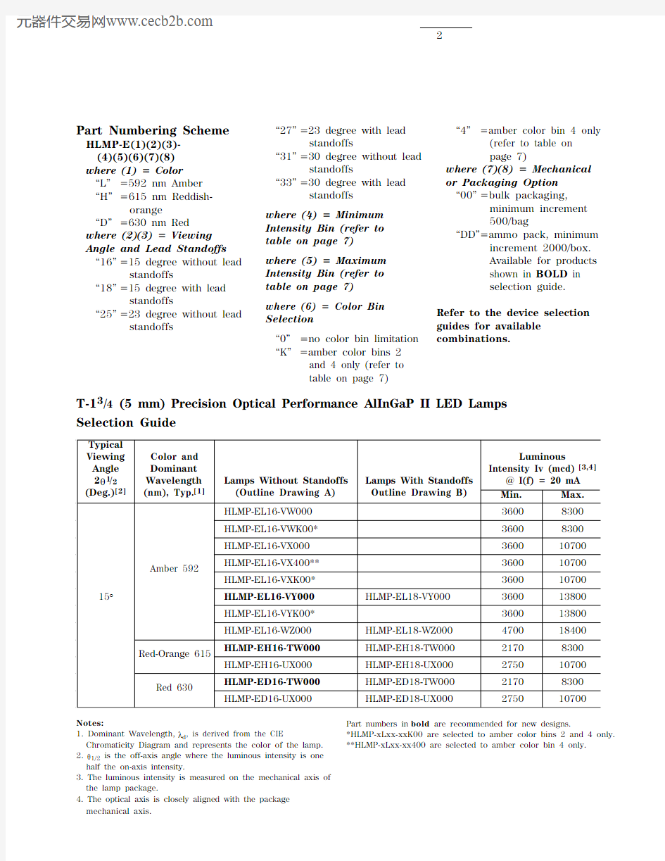
T-13/4 (5 mm) Precision Optical Performance AlInGaP II LED Lamps
Selection Guide
Typical
Viewing Color and Luminous Angle Dominant Intensity Iv (mcd) [3,4] 2θ1/2Wavelength Lamps Without Standoffs Lamps With Standoffs@ I(f) = 20 mA (Deg.)[2](nm), Typ.[1](Outline Drawing A)Outline Drawing B)Min.Max.
HLMP-EL16-VW00036008300
HLMP-EL16-VWK00*36008300
HLMP-EL16-VX000360010700 Amber 592
HLMP-EL16-VX400**360010700
HLMP-EL16-VXK00*360010700 15°HLMP-EL16-VY000HLMP-EL18-VY000360013800
HLMP-EL16-VYK00*360013800
HLMP-EL16-WZ000HLMP-EL18-WZ000470018400 Red-Orange 615
HLMP-EH16-TW000HLMP-EH18-TW00021708300
HLMP-EH16-UX000HLMP-EH18-UX000275010700 Red 630
HLMP-ED16-TW000HLMP-ED18-TW00021708300
HLMP-ED16-UX000HLMP-ED18-UX000275010700
Notes:
1. Dominant Wavelength, λd, is derived from the CIE
Chromaticity Diagram and represents the color of the lamp.
2. θ1/2 is the off-axis angle where the luminous intensity is one
half the on-axis intensity.
3. The luminous intensity is measured on the mechanical axis of
the lamp package.
4. The optical axis is closely aligned with the package
mechanical axis.Part numbers in bold are recommended for new designs.
*HLMP-xLxx-xxK00 are selected to amber color bins 2 and 4 only. **HLMP-xLxx-xx400 are selected to amber color bin 4 only.
T-13/4 (5 mm) Precision Optical Performance AlInGaP II Led Lamps (Continued) Selection Guide
Typical
Viewing Color and Luminous Angle Dominant Intensity Iv (mcd) [3,4] 2θ1/2Wavelength Lamps Without Standoffs Lamps With Standoffs@ I(f) = 20 mA (Deg.)[2](nm), Typ.[1](Outline Drawing A)Outline Drawing B)Min.Max.
HLMP-EL25-ST00016503700
HLMP-EL25-STK00*16503700
HLMP-EL25-SU00016504800
HLMP-EL25-SU400**16504800 Amber 592HLMP-EL25-SUK00*16504800
HLMP-EL25-SVK00*16506300 23°HLMP-EL25-SV000HLMP-EL27-SV00016506300
HLMP-EL25-TW000HLMP-EL27-TW00021708300
HLMP-EL25-TWK00*21708300 Red-Orange 615
HLMP-EH25-SV000HLMP-EH27-SV00016506300
HLMP-EH25-TW000HLMP-EH27-TW00021708300 Red 630
HLMP-ED25-SV000HLMP-ED27-SV00016506300
HLMP-ED25-TW000HLMP-ED27-TW00021708300
HLMP-EL31-SV000HLMP-EL33-SV00016506300
HLMP-EL31-ST00016503700
HLMP-EL31-STK00*16503700 Amber 592HLMP-EL31-SUK00*16504800
HLMP-EL31-SU400**16504800
HLMP-EL31-SU00016504800 30°HLMP-EL31-SVK00*16506300 Red-Orange 615
HLMP-EH31-RU000HLMP-EH33-RU00013004800
HLMP-EH31-SV000HLMP-EH33-SV00016506300
HLMP-ED31-ST00016503700 Red 630
HLMP-ED31-SU00016504800
HLMP-ED31-RU000HLMP-ED33-RU00013004800
HLMP-ED31-SV000HLMP-ED33-SV00016506300 Notes:
1. Dominant Wavelength, λd, is derived from the CIE
Chromaticity Diagram and represents the color of the lamp.
2. θ1/2 is the off-axis angle where the luminous intensity is one
half the on-axis intensity.
3. The luminous intensity is measured on the mechanical axis of
the lamp package.
4. The optical axis is closely aligned with the package
mechanical axis.Part numbers in bold are recommended for new designs.
*HLMP-xLxx-xxK00 are selected to amber color bins 2 and 4 only. **HLMP-xLxx-xx400 are selected to amber color bin 4 only.
Absolute Maximum Ratings at T A = 25°C
DC Forward Current [1,2,3]............................................................50 mA Peak Pulsed Forward Current [2,3]..............................................100 mA Average Forward Current ............................................................30 mA Reverse Voltage (I R = 100 μA).........................................................5 V LED Junction Temperature..........................................................130°C Operating Temperature ..............................................-40°C to +100°C Storage Temperature ..................................................-40°C to +120°C Dip/Drag Solder Temperature................................260°C for 6 seconds Through-the-Wave Preheat Temperature.....................................145°C Through-the-Wave Solder Temperature.................245°C for 3 seconds
[1.59 mm (0.060 in.) below seating plane]
Notes:
1. Derate linearly as shown in Figure 4.
2. For long term performance with minimal light output degradation, drive currents
between 10 mA and 30 mA are recommended. For more information on recommended drive conditions, please refer to Application Brief I-024 (5966-3087E).
3. Please contact your sales representative about operating currents below 10 mA.
A
B
(0.039)
CATHODE
FLAT
Package Dimensions (0.039)
CATHODE
FLAT
B
Electrical/Optical Characteristics at T A = 25°C
Parameter Symbol
Min.
Typ.Max.
Units
Test Conditions Forward Voltage
I F = 20 mA
Amber (λd = 592 nm)
2.15Red-Orange (λd = 617 nm)V F 2.08 2.4V Red (λd = 630 nm) 2.00Reverse Voltage V R 5
20
V
I R = 100 μA
Peak Wavelength Peak of Wavelength of Amber
594Spectral Distribution Red-Orange λPEAK 623nm at I F = 20 mA
Red
639Spectral Halfwidth
?λ1/2
17
nm
Wavelength Width at Spectral Distribution 1/2 Power Point at I F = 20 mA
Speed of Response τs 20ns Exponential Time Constant, e -t/τCapacitance
C 40pF V F
= 0, f = 1 MHz
Thermal Resistance R ΘJ-PIN
240
°C/W
LED Junction-to-Cathode Lead
Luminous Efficacy [1]Emitted Luminous
Amber
500Power/Emitted Radiant Red-Orange ηv
235lm/W
Power at I f = 20 mA
Red
155
Note:
1. The radiant intensity, I e , in watts per steradian, may be found from the equation I e = I v /ηv , where I v is the luminous intensity in candelas and ηv is the luminous efficacy in lumens/watt.
s
Figure 1. Relative Intensity vs. Peak Wavelength.
WAVELENGTH – nm
R E L A T I V E I N T E N S I T Y
Figure 2. Forward Current vs.Forward Voltage.
C U R R E N T – m A
V F – FORWARD VOLTAGE – V
Figure 6. Representative Spatial Radiation Pattern for 24° Viewing Angle Lamps.
N O R M A L I Z E D I N T E N S I T Y
1.000ANGULAR DISPLACEMENT – DEGREES
0.800.600.500.700.20-20
-15
0.100.300.40-10
5
10
15
20
25
0.90-25
-5
Figure 3. Relative Luminous Intensity vs. Forward Current.
Figure 4. Maximum Forward Current vs. Ambient Temperature. Derating Based on T JMAX = 130°C.
I F – F O R W A R D C U R R E N T –
m A
T A – AMBIENT TEMPERATURE – °C
R E L A T I V E L U M I N O U S I N T E N S I T Y (N O R M A L I Z E D A T 20 m A )
00
I F – DC FORWARD CURRENT – mA
402.0
1.5
1.0
0.52050
2.5
1030Figure 5. Representative Spatial Radiation Pattern for 15° Viewing Angle Lamps.
N O R M A L I Z E D I N T E N S I T Y
1.000ANGULAR DISPLACEMENT – DEGREES
0.800.600.500.700.20-20
-15
0.100.300.40-10
5
10
15
20
25
0.90
-25
-5
Bin Name Min.Max.1584.5587.02587.0589.54589.5592.06
592.0
594.5
Bin Name Min.Max.P 8801150Q 11501500R 15001900S 19002500T 25003200U 32004200V 42005500W 55007200X 72009300Y 930012000Z
12000
16000
Intensity Bin Limits (mcd at 20 mA)
Tolerance for each bin limit is ± 15%.
HLMP-xLxx Color Bin Limits (nm at 20 mA)
Tolerance for each bin limit is ± 0.5 nm.
Note:
1.Bin categories are established for classification of products. Products may not be available in all bin categories.
N O R M A L I Z E D I N T E N S I T Y
ANGULAR DISPLACEMENT – DEGREES
Figure 7. Representative Spatial Radiation Pattern for 30° Viewing Angle Lamps.
https://www.360docs.net/doc/1315321463.html, Data subject to change.
Copyright ? 1999 Agilent Technologies Obsoletes 5968-7180E
5968-4303E (11/99)