VBO20-16AO2中文资料

? 2004 IXYS All rights reserved
1 - 2
IXYS reserves the right to change limits, test conditions and dimensions.
420
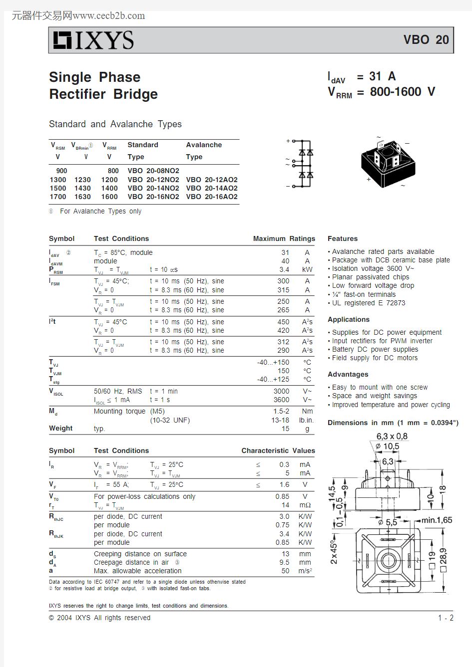
I dAV = 31 A
V RRM = 800-1600 V
Standard and Avalanche Types
V RSM V BRmin ①V RRM Standard Avalanche V V V Type
Type
900 800VBO 20-08NO2130012301200VBO 20-12NO2VBO 20-12AO2150014301400VBO 20-14NO2VBO 20-14AO21700
1630
1600
VBO 20-16NO2
VBO 20-16AO2
① For Avalanche Types only
Symbol Test Conditions
Maximum Ratings
I dAV ②T C = 85°C, module 31A I dAVM module 40A P RSM T VJ = T VJM t = 10 μs 3.4kW I FSM
T VJ = 45°C;t = 10 ms (50 Hz), sine 300A V R = 0t = 8.3 ms (60 Hz), sine 315A T VJ = T VJM t = 10 ms (50 Hz), sine 250A V R = 0
t = 8.3 ms (60 Hz), sine 265A I 2t
T VJ = 45°C t = 10 ms (50 Hz), sine 450A 2s V R = 0t = 8.3 ms (60 Hz), sine 420A 2s T VJ = T VJM t = 10 ms (50 Hz), sine 312A 2s V R = 0
t = 8.3 ms (60 Hz), sine
290A 2s T VJ -40...+150
°C T VJM 150°C T stg -40...+125
°C V ISOL 50/60 Hz, RMS t = 1 min 3000V~
I ISOL ≤ 1 mA
t = 1 s
3600V~M d Mounting torque (M5)
1.5-2Nm (10-32 UNF)
13-18lb.in.Weight typ.
15
g
Features
?Avalanche rated parts available
?Package with DCB ceramic base plate ?Isolation voltage 3600 V~
?Planar passivated chips ?Low forward voltage drop ??" fast-on terminals ?UL registered E 72873Applications
?Supplies for DC power equipment ?Input rectifiers for PWM inverter ?Battery DC power supplies ?Field supply for DC motors Advantages
?Easy to mount with one screw ?Space and weight savings
?Improved temperature and power cycling Symbol Test Conditions Characteristic Values
I R V R = V RRM ;T VJ = 25°C ≤0.3mA V R = V RRM ;T VJ = T VJM ≤5mA V F I F
= 55 A;
T VJ = 25°C
≤
1.6V V T0For power-loss calculations only 0.85V r T T VJ = T VJM
14m ?R thJC per diode, DC current 3.0K/W per module
0.75K/W R thJK per diode, DC current 3.4K/W per module
0.85K/W d S Creeping distance on surface 13mm d A Creepage distance in air ③9.5mm a
Max. allowable acceleration
50
m/s 2
Dimensions in mm (1 mm = 0.0394")
Data according to IEC 60747 and refer to a single diode unless otherwise stated ② for resistive load at bridge output, ③ with isolated fast-on tabs.Single Phase Rectifier Bridge
~
~
+
–
+
–
~~
? 2004 IXYS All rights reserved
2 - 2
IXYS reserves the right to change limits, test conditions and dimensions.
420
Fig. 1Surge overload current per diode
I FSM : Crest value, t: duration
Fig. 3Max. forward current at case
temperature
Fig. 2I 2t versus time (1-10 ms)
per diode Fig. 4Power dissipation versus direct output current and ambient temperature
Fig. 5Transient thermal impedance junction to heatsink per diode
Constants for Z thJK calculation:i
R
thi (K/W)
t i (s)10.7750.07882 1.3900.5043
1.255
3.701