3161中文资料
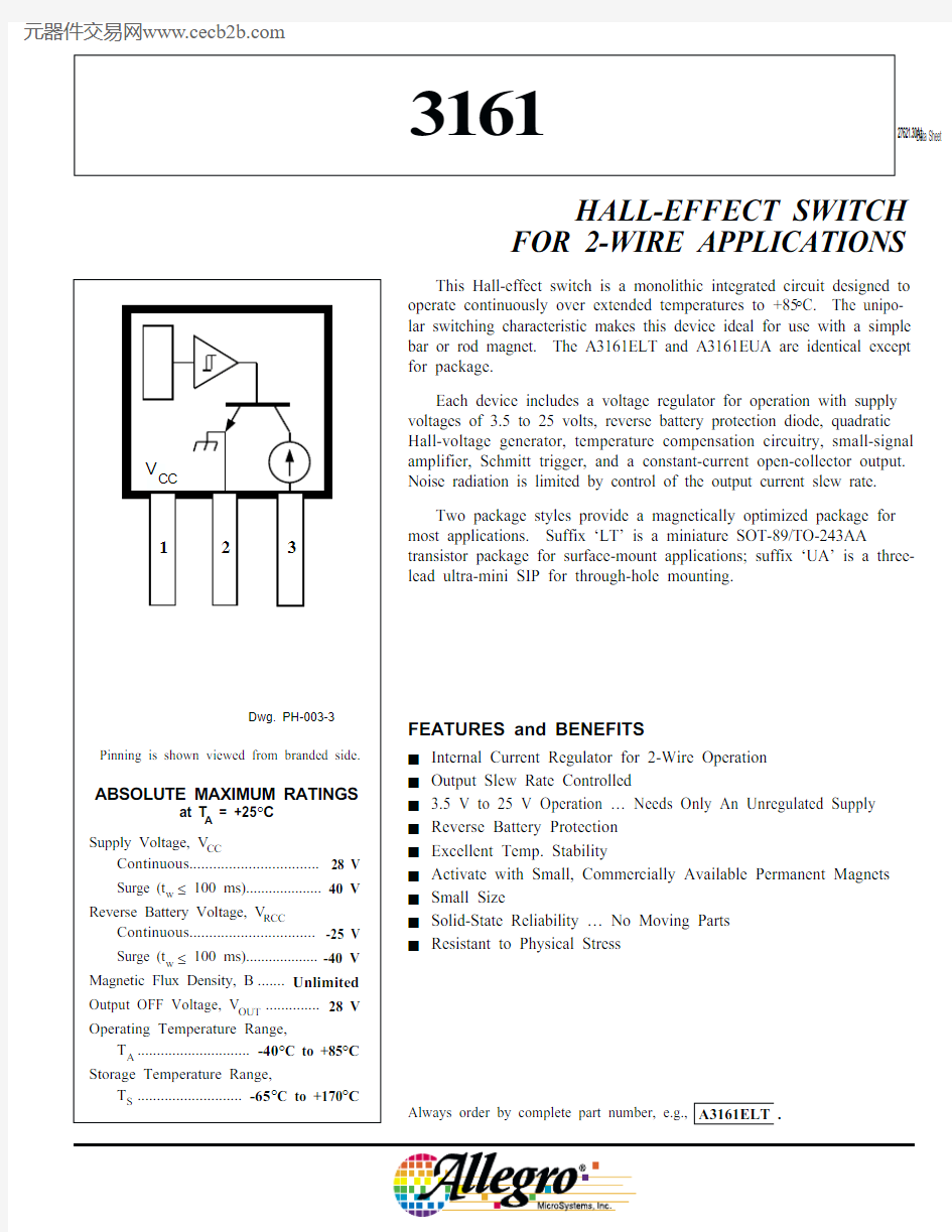
This Hall-effect switch is a monolithic integrated circuit designed to operate continuously over extended temperatures to +85°C. The unipo-lar switching characteristic makes this device ideal for use with a simple bar or rod magnet. The A3161ELT and A3161EUA are identical except for package.
Each device includes a voltage regulator for operation with supply voltages of 3.5 to 25 volts, reverse battery protection diode, quadratic Hall-voltage generator, temperature compensation circuitry, small-signal amplifier, Schmitt trigger, and a constant-current open-collector output.Noise radiation is limited by control of the output current slew rate.Two package styles provide a magnetically optimized package for most applications. Suffix ‘LT’ is a miniature SOT-89/TO-243AA
transistor package for surface-mount applications; suffix ‘UA’ is a three-lead ultra-mini SIP for through-hole mounting.
HALL-EFFECT SWITCH FOR 2-WIRE APPLICATIONS
Always order by complete part number, e.g., A3161ELT .
Data Sheet 27621.30A?
FEATURES and BENEFITS
I Internal Current Regulator for 2-Wire Operation I Output Slew Rate Controlled
I 3.5 V to 25 V Operation … Needs Only An Unregulated Supply I Reverse Battery Protection I Excellent Temp. Stability
I Activate with Small, Commercially Available Permanent Magnets I Small Size
I Solid-State Reliability … No Moving Parts I
Resistant to Physical Stress
3161
3161
HALL-EFFECT SWITCH
FOR 2-WIRE APPLICATIONS
115 Northeast Cutoff, Box 15036
Worcester, Massachusetts 01615-0036 (508) 853-5000
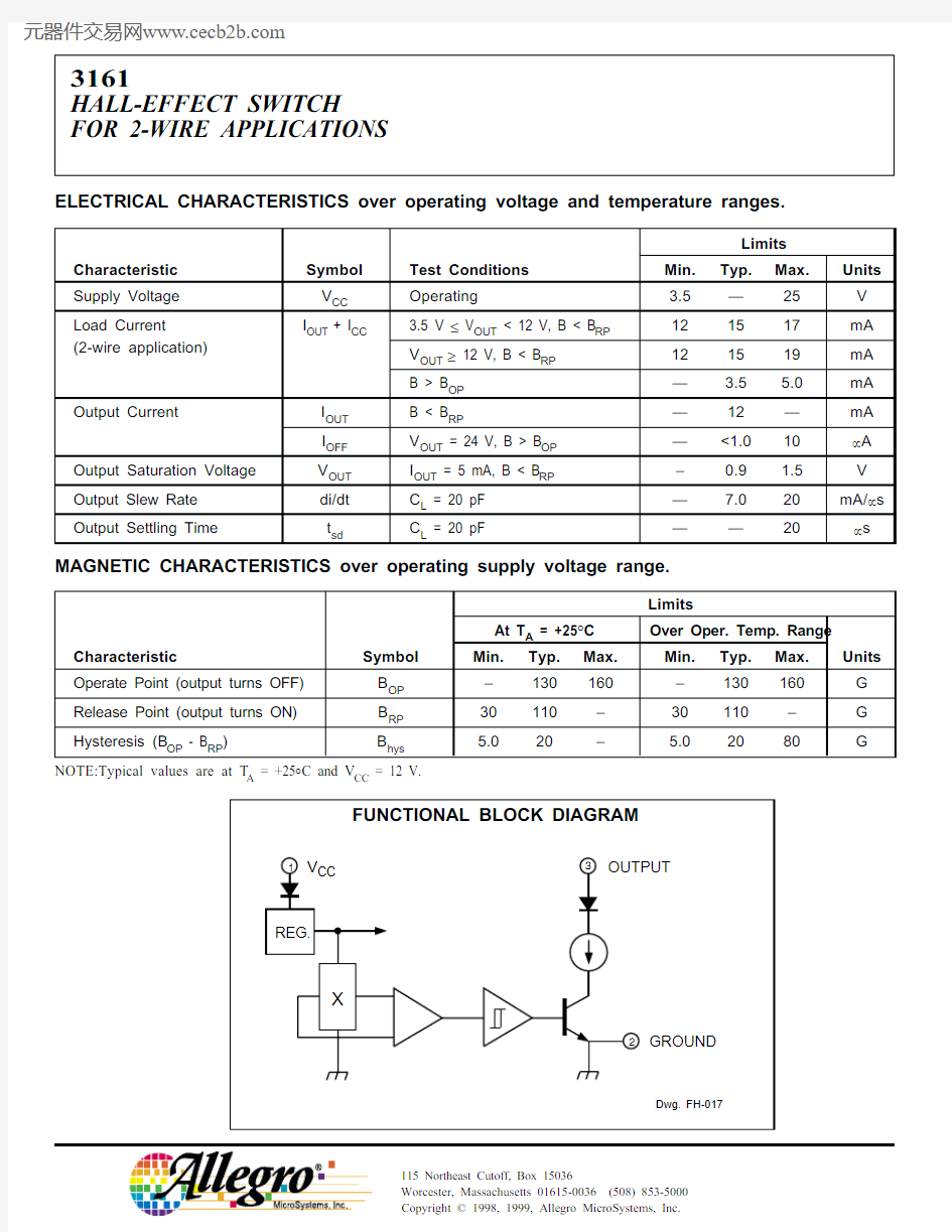
ELECTRICAL CHARACTERISTICS over operating voltage and temperature ranges.
Copyright ? 1998, 1999, Allegro MicroSystems, Inc.
3161
HALL-EFFECT SWITCH FOR 2-WIRE APPLICATIONS
https://www.360docs.net/doc/2219087987.html,
SWITCH POINTS
TOTAL SUPPLY CURRENT
TYPICAL OPERATING CHARACTERISTICS
OUTPUT SATURATION VOLTAGE
SAFE OPERATING AREA
50
100
AMBIENT TEMPERATURE in °C
-50
Dwg. GH-044-1
S W I T C H P O I N T i n G A U S S
150
200
100
50
150
0-25
25
75
125
0T O T A L S U P P L Y C U R R E N T (I O U T + I C C ) i n m A
20
15
25
50
75
100
AMBIENT TEMPERATURE in °C
-50
Dwg. GH-028-4
125
-25
150
5.0
10
25
15
5
AMBIENT TEMPERATURE in °C
M A X I M U M C O N T I N U O U S S U P P L Y V O L T A G E i n V O L T S
Dwg. GH-068
30
20
10
025********
AMBIENT TEMPERATURE in °C
800
400
-50
Dwg. GH-029-3
S A T U R A T I O N V O L T A G E i n m V
-251000600
200
3161
HALL-EFFECT SWITCH
FOR 2-WIRE APPLICATIONS
115 Northeast Cutoff, Box 15036
Worcester, Massachusetts 01615-0036 (508) 853-5000
OPERATION
The output of these devices (pin 3) switches OFF when the magnetic field at the Hall sensor exceeds the operate point threshold (B OP ). When the magnetic field is reduced to below the release point threshold (B RP ), the device output switches ON. The difference in the magnetic operate and release points is called the hysteresis (B hys ) of the device. This built-in hysteresis allows clean switching of the output even in the presence of external mechanical vibration and electrical noise.
APPLICATIONS INFORMATION
These devices are normally operated in a 2-wire mode, where the supply terminal and the output terminal are tied together. An external comparator detects the change in total supply current by the addition (output off, B > B OP )or subtraction (output on, B < B RP ) of I OUT .
Hall effect applications information is available in the “Hall-Effect IC Applications Guide”, which can be found in the latest issue of the Allegro MicroSystems Electronic Data Book , AMS-702 or Application Note 27701,or at https://www.360docs.net/doc/2219087987.html, .
TYPICAL 2-WIRE APPLICATION
UT
100
125
150
175
200
3.0
0O U T P U T C U R R E N T i n m A
MAGNETIC FLUX DENSITY in GAUSS
12
9.0
6.0
75
Dwg. GH-007-1
50
25
15
3161 HALL-EFFECT SWITCH FOR 2-WIRE APPLICATIONS
https://www.360docs.net/doc/2219087987.html, PACKAGE DESIGNATOR ‘LT’
Dimensions in Inches
(for reference only)
Dimensions in Millimeters
(controlling dimensions)
0.44
0.35
3161
HALL-EFFECT SWITCH
FOR 2-WIRE APPLICATIONS
115 Northeast Cutoff, Box 15036
Worcester, Massachusetts 01615-0036 (508) 853-5000
PACKAGE DESIGNATOR ‘UA’
Dimensions in Inches Dimensions in Millimeters
(controlling dimensions)
(for reference only)
NOTES:1.Tolerances on package height and width represent allowable mold offsets.
Dimensions given are measured at the widest point (parting line).
2.Exact body and lead configuration at vendor’s option within limits shown.
3.Height does not include mold gate flash.
Dwg. MH-014E in
0.050
BSC
°
Dwg. MH-014E mm
1.27
BSC
°
0.480.36
3161 HALL-EFFECT SWITCH FOR 2-WIRE APPLICATIONS
https://www.360docs.net/doc/2219087987.html,
The products described herein are manufactured under one or more of the following U.S. patents: 5,045,920; 5,264,783; 5,442,283;
5,389,889; 5,581,179; 5,517,112; 5,619,137; 5,621,319; 5,650,719; 5,686,894; 5,694,038; 5,729,130; 5,917,320; and other patents pending.
Allegro MicroSystems, Inc. reserves the right to make, from time to time, such departures from the detail specifications as may be required to permit improvements in the performance, reliability, or manufacturability of its products. Before placing an order, the user is cautioned to verify that the information being relied upon is current.
Allegro products are not authorized for use as critical components in life-support appliances, devices, or systems without express written approval.
The information included herein is believed to be accurate and reliable. However, Allegro MicroSystems, Inc. assumes no responsibil-ity for its use; nor for any infringements of patents or other rights of third parties that may result from its use.
3161
HALL-EFFECT SWITCH
FOR 2-WIRE APPLICATIONS
115 Northeast Cutoff, Box 15036
Worcester, Massachusetts 01615-0036 (508) 853-5000
HALL-EFFECT SENSORS
Partial Part Avail. Oper.Characteristics at T A = +25°C Number Temp.B OP max B RP min B hys typ Features
Notes
HALL-EFFECT UNIPOLAR SWITCHES in order of B OP and B hys 3240E/L +50+5.010chopper stabilized 13209E ±60±5.07.7400 μW, chopper stabilized 3210E ±60±5.07.725 μW, chopper stabilized 3361E +110+55 5.0*2-wire, chopper stabilized
3362E +110+55 5.0*2-wire, chopper stabilized, inverted output 3161E +160+30202-wire
3141E/L +160+10553235S +175+2515*output 12-25-17515*output 2
25140E +200+5055300 mA power driver output
1
3142E/L +230+75553143E/L +340+165553144E/L +350+50553122E/L +400+1401053123E/L +440+1801053121
E/L
+450
+125
105
HALL-EFFECT LATCHES & BIPOLAR SWITCHES ?
in order of B OP and B hys
3260E/L +30-3020bipolar switch, chopper stabilized 3280E/L +40-4045chopper stabilized 3134E/L +50-5027bipolar switch 3133K/L/S +75-7552bipolar switch 3281E/L +90-90100chopper stabilized 3132K/L/S +95-9552bipolar switch 3187E/L +150-150100*3177S +150-1502003625S +150-150200900 mA power driver output 1, 33626S +150-150200400 mA power driver output 1, 33195E/L +160-160220active pulldown 13197L +160-16023013175S +170-1702003188E/L +180-180200*3283E/L +180-180300chopper stabilized 3189E/L +230-230100*3275S +250-250100*33185E/L +270-270340*Operating Temperature Ranges:
S = -20°C to +85°C, E = -40°C to +85°C, J = -40°C to +115°C, K = -40°C to +125°C, L = -40°C to +150°C Notes 1.Protected.
2.Output 1 switches on south pole, output 2 switches on north pole for 2-phase, bifilar-wound, unipolar-driven brushless dc motor control.
https://www.360docs.net/doc/2219087987.html,plementary outputs for 2-phase bifilar-wound, unipolar-driven brushless dc motor control.*Minimum. ? Maximum
?Latches will not switch on removal of magnetic field; bipolar switches may switch on removal of field but require field reversal for reliable operation over operating temperature range.