ibapda-v6_v1.9_en_a4
i b a P D
A -V 6
Extended Technostring Functions
The Technostring is a way to supply ibaPDA with more information by means of an ASCII-string. Multiple Technostrings from different sources may be used and an unlimited number of information fields may be derived from the Technostrings. The Technostring data are available for each data file – they may be stored as header information in the data file or used in the naming of the data files.
Virtual Signals + Expression Editor
Virtual signals can be created using arithmetic and boolean operations via the expression editor. These signals can be treated like raw data signals, i.e. they can be recorded to the data file, whilst also being used as a trigger mechanism. The expression editor is very similiar to the one in ibaAnalyzer.
Generation of Alarm Signals
ibaPDA-V6 offers up to 64 digital output signals. During measurement live signals may be monitored and compared with limits in order to generate event or alarm signals. The output signals can be defined easily by using the expression editor in the I/O Manager. As process interface for the outputs all ibaFob devices with output capability can be used.
Flexible Recording
Multiple data storages can be configured for recording data. Each data storage has its own profile, with independent sample time, pre and post triggers, hard disk cleanup strategy and post processing command. All data storages can create data files and store their data simultaneously. Additionally, each data storage can work in overlapping recording mode with two or more files.
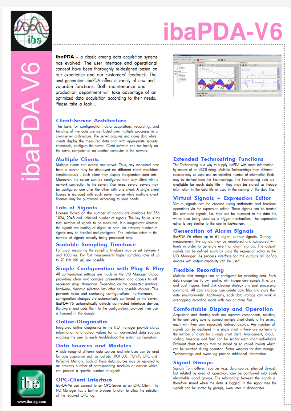
Comfortable Display and Operation
Acquisition and charting tools are separate components, resulting in the user being able to connect multiple chart clients to the server, each with their own separately defined display. Any number of signals can be displayed in a single chart – there are no limits to the number of charts for a single chart client. Arrangement, layout, scaling, timebase and feed can be set for each chart individually. Different chart settings may be stored as so called layouts which can be switched during operation. Status windows for data storage, Technostrings and event log provide additional information.
Signal Groups
Signals from different sources (e.g. data source, physical device), but related by area of operation, can be combined into easily identifiable signal groups. The relationship between the signals is therefore stored when the data is logged. In the signal tree the signals can be sorted by groups, even later in ibaAnalyzer.
ibaPDA – a classic among data acquisition systems has evolved. The user interface and operational concept have been thoroughly re-designed based on our experience and our customers’ feedback. The next generation ibaPDA offers a variety of new and valuable functions. Both maintenance and production department will take advantage of an optimized data acquisition according to their needs. Please take a look…
Client-Server Architecture
The tasks for configuration, data acquisition, recording, and trending of live data are distributed over multiple processes in a client-server architecture. The server acquires and stores data while clients display the measured data and, with appropriate security credentials, configure the server. Client software can run locally on the server computer or on another computer in the network.
Multiple Clients
Multiple clients can access one server. Thus, any measured data from a server may be displayed on different client machines simultaneously . Each client may display independent data sets. Moreover, the server can be configured from any client with a network connection to the server. Vice versa, several servers may be configured one after the other with one client. A single client license is included with each server license while multiple client licenses may be purchased according to your needs.
Lots of Signals
Licenses based on the number of signals are available for 256, 1024, 2048 and unlimited number of signals. The key figure is the total number of signals to be measured. It is insignificant whether the signals are analog or digital or both. An arbitrary number of signals may be installed and configured. The limitation refers to the number of signals actually being processed only.
Scalable Sampling Timebase
For usual measuring the sampling timebase may be set between 1 and 1000 ms. For fast measurements higher sampling rates of up to 20 kHz (50 μs) are possible.
Simple Configuration with Plug & Play
All configuration settings are made in the I/O Manager dialog, providing clear and concise presentation and access to all necessary setup information. Depending on the connected interface hardware, dynamic selection lists offer only possible choices. This prevents false and confusing configurations. Furthermore, configuration changes are automatically confirmed by the server. ibaPDA-V6 automatically detects connected interface devices (hardware) and adds them to the configuration, provided their use is licensed in the dongle.
Online-Diagnostics
Integrated online diagnostics in the I/O manager provide status information and actual values for all connected data sources enabling the user to easily troubleshoot the system configuration.
Data Sources and Modules
A wide range of different data sources and interfaces can be used for data acquisition such as ibaFob, PROFIBUS, TCP/IP, OPC and Reflective Memory. Each of these data sources may be assigned to an arbitrary number of corresponding modules or devices which can process a specific number of signals.
OPC-Client Interface
ibaPDA-V6 can connect to an OPC-Server as an OPC-Client. The I/O Manager has a built-in browser function to allow the selection of the required OPC tag.
Technical Data
System Architecture Client / server
No. of Clients 1 or more; depends on license (dongle)
No. of Signals Licenses based on no. of signals; grades: 256, 1024, 2048 and unlimited; figures refer to total no. of signals (sum of analog and digital signals); no rigid relation between analog and digital signals. Operating System Windows XP Professional, Windows 2000 Professional, Windows 2003 Server Hardware IBM-compatible PC, P4 1GHz, 256 MB RAM 40 GB HDD or better
Configuration I/O Manager Central configuration of all devices (modules), signals, signal groups, alarms and Technostrings User support by means of dynamic selection lists for module configuration
Auto-Detect Automatic detection of connected hardware (Plug&Play) and automatic display of licensed module types Online-Diagnostics Integrated in I/O manager
Signal Groups Signals of different data sources can be assigned to signal groups according to technological relations. No. of groups unlimited
Technostring Unlimited no. of Technostrings; unlimited no. of info-fields can be derived from each Technostring; interfaces: COM, TCP/IP, OPC, Reflective Memory and text files
Virtual Signals / Expression Editor Virtual signals can be created by means of an expression editor;
virtual signals may be displayed, recorded and combined with real signals. ? creation of complex triggering conditions
? online-evaluation (e.g. sum, difference)
Alarm Outputs Up to 64 digital output signals, definition by expression editor. Output cycle: 100 ms. Output via ibaFOB-io or ibaFOB-4-o, ibaNet750-BM, ibaPADU-8-O, ibaLink-SM-64-io etc. Data Sources / Module Types
ibaFOB..:
ibaPADU..., ibaBM-SM..., ibaBM-SLM, ibaBM-DDCSM, ibaBM-DPM-64, ibaNet750-BM (WAGO)
FastFob for fast measurement (up to 50 μs) with appropriate hardware. Simadyn D, Simatic TDC via ibaFOB-SD / TDC
ibaCom-L2B: PROFIBUS DP, S7 DirectAccess, S7 SymbolicRequest TCP/IP: EtherNet/IP, Modbus, VIP, Sisteam, ibaLogic
OPC:
ibaPDA = OPC-Client (OPC DA 1.0, -DA 2.0 and -DA 3.0) Reflective Memory: VMIxxx 5565, 5576, 5579, 5588
DGM200P: ALSPA C80 HPC/HPCi, DGM200 fast system bus SramNet+
SC150 / SC150e
Module Structure
Module = device / data source
No. of signals per module not fixed to 32 digital + 32 analog signals; no. and shares of digital and analog signals in one module are subject to definition, depending on the device.
Sample Time
Basic sample time: 1 ...1000 ms, fast measurement with appropiate hardware components up to 50 μs. Output cycle for alarm signals: 100 ms.
For each module a special sample time can be set (multiple of basic sample time).
Data Storage Data Storage
Unlimited no. of independent data storages;
each data storage can run in overlapping mode with two or more files; change of data storage configuration does not force restart of data acquisition. Data Storage Profiles Stored in a pool, can be used by all recorders; no. unlimited;
Signal Compression Data recording with multiples of sample time;
optional: recording actual, average, min or max value in the corresponding time segment Manual Triggers 1 start- and 1 stop trigger per recorder for manual start and stop of recording
Charts Display No. of Charts Unlimited
No. of Curves Unlimited, per chart and graph as well
Operation Look-and-feel like ibaAnalyzer (drag&drop, free scaling, zooming etc.) Scaling Separated or common Y-axes, automatic and manual scaling Feed Individual time base, i.e. feeding speed for each chart;
feed may be stopped and restarted any time without affecting the data acquisition and recording; Chart Layout
Unlimited no. of chart layouts and arrangements can be configured and stored; switching between different layouts during operation no problem;
Operation / Information Signal Tree Display of all configured modules and signals in order by module numbers (with or without module symbol) or by signal groups; dockable window
Recorder Status and Technostring Display of all configured recorders with their recording status, path and filename of the data files; dockable window, Technostring: Display of status and contents Event Log
Logging and display of system events; dockable window
ibaAnalyzer version 4.2 or higher is required for reading data files created by ibaPDA-V6.
flyer_PDA_ibaPDAV6_v1.9_en_A4 05.02.2007