KRVV3220G471NXT
GRACE
SMD Multilayer chip Varistor
PART NO. KRVV3220G471NXT
1.1 Technical Data Symbol V alue Unit Maximum allowable continuous AC voltage*1V RMS300 V Maximum allowable continuous DC voltage V DC380 V V aristor voltage Measured*2V B470 V V aristor voltage tolerance ±10 % Typical capacitance value measured*3 C 80 pF Typical capacitance value tolerance ±30 % Maximum clamping voltage measured*4V C775 V Rated peak single pulse transient current at *5I P500 A 1.2 Reference Data
Maximum Energy Absorption 10/1000μs I 5 J Response time T rise<1 ns Leakage current at V B×80%(At initial state) I L VB<20 μΑLeakage current at V B×80%(After reliability Test) I L VBA<100 μΑOperating ambient temperature -40~+85 ℃Storage temperature -40~+125 ℃Reflow temperature profile(Recommend) 260 ℃1.3 Other Data
Body ZnO
End termination Ag/Ni/Sn
Packaging Tape
Complies with Standard IEC61000-4-2、IEC61000-4-5
Notes:
*1 AC voltage at 50~60Hz
*2 Varistor voltage Measured at 1mA DC
*3 Capacitance Measured at f=1kHz,Vrms=0.5V
*4 Maximum clamping voltage Measured at 1A by 8/20μs Pulse
*5 Rated peak single pulse transient current Measured by 8/20μs Pulse
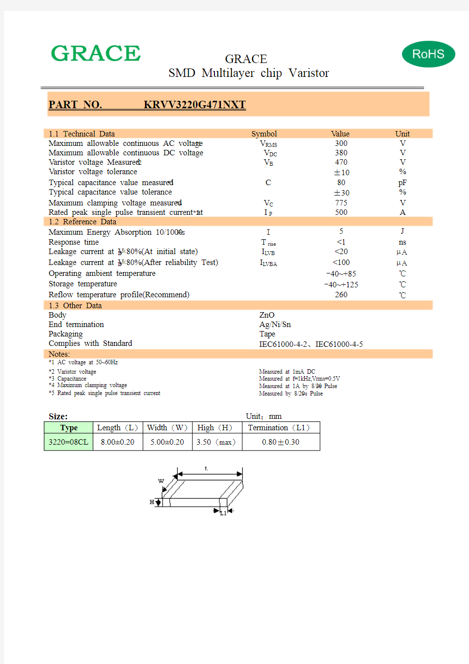
Size:Unit:mm
Type Length(L)Width(W)High(H)Termination(L1)
3220=08CL 8.00±0.20 5.00±0.20 3.50(max)0.80±0.30
GRACE
SMD Multilayer chip Varistor
2. Ordering Information 2.1 Standards
KRVV 3220 G 471 N X T ① ② ③ ④ ⑤ ⑥ ⑦
①production series : GRACE V aristor ②size :3220
③type :G:general ; E :ESD ; H :high energy
V aristor voltage (V ④1mA ): 471=470V , 390=39V ,8R0=8.0V ⑤end termination: S: Ag/Pd N: Ag/Ni/Sn
⑥ypical capacitance value measured : X:无容值要求; 361=360pf ⑦package :T: taping B: bulk
3.Size
Model 3216(1206) 3225(1210) 4532(1812) 5650(2220) 08CL(3220) 10CL(4032)
12CL(4840) Length(L) 3.20±0.20 3.20±0.20 4.50±0.20 5.60±0.20 8.00±0.20 10.0±0.20 12.0±0.20 Width(W) 1.60±0.20 2.50±0.20 3.20±0.20 5.00±0.20 5.00±0.20 8.00±0.20 10.0±0.20 High(H )
1.60max
2.50max
3.00max 3.50max 3.50max
3.50max
3.50max
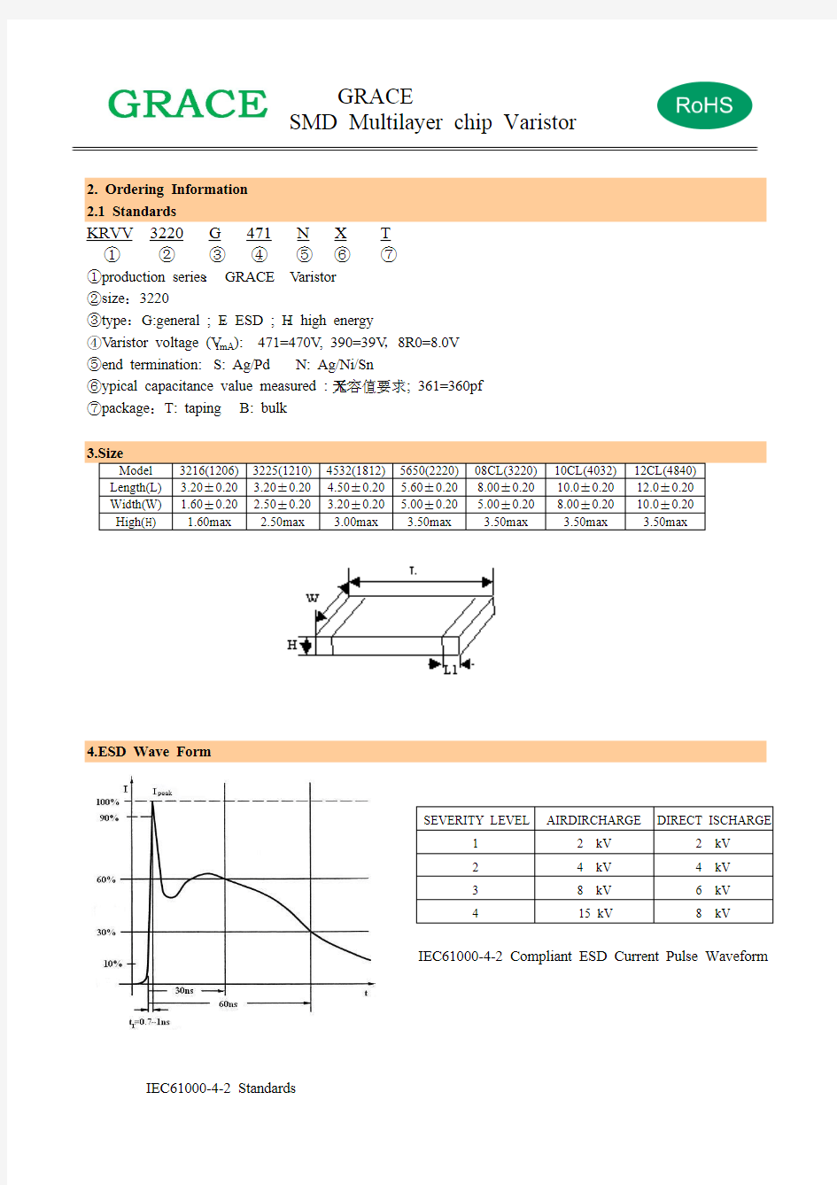
4.ESD Wave Form
IEC61000-4-2 Compliant ESD Current Pulse Waveform
IEC61000-4-2 Standards
SEVERITY LEVEL
AIRDIRCHARGE DIRECT ISCHARGE
1 2 kV 2 kV 2 4 kV 4 kV 3 8 kV 6 kV 4
15 kV
8 kV
5.Surge Wave Form
IEC61000-4-5 Standards
6.Enviromental Reliability Test
Characteristic Test method and description
High Temperature Storage The specimen shall be subjected to 125℃ for 1000 hours in a thermostatic bath without
load and then stored at room temperature and humidity for 1 to 2 hours. The change of
varistor voltage shall be within 10%.
Step Temperature Period 1 -40±3℃ 30min ±3 2 Room Temperature 1~2hours 3 125±2℃
30min ±3
Temperature Cycle The temperature cycle of specified temperature shall be repeated five times and then stored at room temperature and humidity for one two hours. The change of varistor voltage shall be within 10%and mechanical damage shall be examined.
4
Room Temperature 1~2hours
High Temperature Load After being continuously applied the maximum allowable voltage at 85℃ for
1000hours, the specimen shall be stored at room temperature and humidity for one or
hours, the change of varistor voltage shall be within 10%.
Damp Heat Load/
Humidity Load
The specimen should be subjected to 40℃,90 to 95%RH environment, and the
maximum allowable voltage applied for 1000 hours, then stored at room temperature
and humidity for one or two hours. The change of varistor voltage shall be within 10%. Low Temperature Storage The specimen should be subjected to -40℃, without load for 1000 hours and then
stored at room temperature for one two hours. The change of varistor voltage shall be
within 10%.
7.Soldering Recommendation
The principal techniques used for the soldering of components in surface mount technology are infrared reflow and wave soldering.
7.1 Wave Soldering
When wave soldering. The MLCV is attach to the circuit board by means of an adhesive. The assembly is then place on a conveyor and run though the soldering process to contact the wave. Wave soldering is the most strenuous of the processes. To avoid the possibility of generating stresses due to thermal shock., a preheat stage in the soldering process is recommended, and the peak temperature of the solder process should be rigidly controlled. The following is the typical profiles.
SEVERITY LEVEL
T1 T2 1
8 μs
20 μs
WA VE SOLDER PROFILE
7.2 Reflow Soldering
When reflow soldering, the device is placed a solder paste on the substrate ,as the solder paste is heated, it re-flows and solders the unite to board. When using a reflow process ,care should be taken to ensure that the MLCV is not subjected to an thermal gradient steeper than 4 degrees per second; the ideal gradient being 2degrees per second. During the soldering process, preheating to within 100 degrees of the soldier’s peak temperature is essential to minimize thermal shock. The following is typical profile.
REFLOW SOLDER PROFILE
8 Packaging Specification
8.1 Carrier tape transparent cover tape should be heat-sealed to carry the products, and the reel should be used to reel the carrier tape.
8.2 The adhesion of the heat-sealed cover tape shall be 40﹢20/﹣15 grams .
8.3 Both the head and the end portion of taping shall be empty for reel package and SMT auto-pickup machine. And a normal paper tape shall be connected in the head of taping for the operator handle.
type A 0 ±0.10 B 0 ±0.10 K 0 ±0.10 T ±0.05 T 2 ±0.05 D 0
+0.10
-0.00 D 1 ±0.05 P 1 ±0.10 P 2 ±0.05 P 0 ±0.05 W ±0.20 E ±0.10 F
±0.05
1005 1.08 1.88 1.04 0.22 0.10 1.50 1.00 4.00 2.00 4.00 8.00 1.75 3.50 1608 1.08 1.88 1.04 0.22 0.10 1.50 1.00 4.00 2.00 4.00 8.00 1.75 3.50 2012 1.42 2.30 1.04 0.22 0.10 1.50 1.00 4.00 2.00 4.00 8.00 1.75 3.50 3216 1.88 3.50 1.27 0.20 0.10 1.50 1.00 4.00 2.00 4.00 8.00 1.75 3.50 3225 2.18 3.46 1.45 0.22 0.10 1.50 1.00 4.00 2.00 4.00 8.00 1.75 3.50 4532 3.66 4.95 1.74 0.25 0.10 1.50 1.50 8.00 2.00 4.00 12.00 1.75 5.50 5650
5.10
5.97
2.80
0.25
0.10
1.50
1.50
8.00
2.00
4.00
12.00
1.75
5.50
9. Reel Dimension
type A B C D E W W1
1005 178.0±1.0 60.0±0.5 13.0±0.2 21.0±0.2 2.0±0.5 9.0±0.50 1.5±0.15
1608 178.0±1.0 60.0±0.5 13.0±0.2 21.0±0.2 2.0±0.5 9.0±0.50 1.5±0.15
2012 178.0±1.0 60.0±0.5 13.0±0.2 21.0±0.2 2.0±0.5 9.0±0.50 1.5±0.15
3216 178.0±1.0 60.0±0.5 13.0±0.2 21.0±0.2 2.0±0.5 9.0±0.50 1.5±0.15
3225 178.0±1.0 60.0±0.5 13.0±0.2 21.0±0.2 2.0±0.5 9.0±0.50 1.5±0.15
4532 178.0±1.0 60.0±0.5 13.5±0.1 21.0±0.2 2.0±0.5 13.6±0.2 1.5±0.15
5650 178.0±1.0 60.0±0.5 13.5±0.1 21.0±0.2 2.0±0.5 13.6±0.2 1.5±0.15
type 1206(3216) 1210(3225) 1812(4532) 2220(5650) 3220(08CL) 4032(10CL) 4840(12CL) paper - - - - - quantity
plastic 3000 3000 1000 1000 1000/500 2000 2000 Minimum ordering 3000 3000 1000 1000 1000 2000 2000