811PH
DOCUMENT CONTROL NUMBER /
? 2001 Tyco Electronic Product Group
PAGE 1 of 6
Registered Office: 19-21 Denmark Street, Wokingham, Berks RG40 2QE
801PH/811PH ADDRESSABLE OPTICAL SMOKE & HEAT DETECTOR
PRODUCT APPLICATION & DESIGN INFORMATION
1.
INTRODUCTION
The 801PH/811PH optical smoke and heat detector forms part of the 800 Series Addressable Fire detectors.The 811PH is the marine version of the 801PH.The detector is intended to plug into one of the following:
?Minerva Universal Base (formerly known as an M6/900 Universal Base) ?801IB isolator base ?801RB relay base ?
801SB sounder base
The detector is designed to transmit, to a remote Minerva MX/T2000/Minerva SOLO fire controller, digital signals which represent status of the optical smoke and heat elements of the detector.
Software within the controller is used to interpret the returned optical and heat values to raise alarm or other appropriate response according to the type of detector configured in ‘MX CONSYS ’ (refer to Publication 17A-06-X1).The mode of detector may be:
?Optical smoke only detector (sensitivity High,Normal or Low)
?HPO smoke detector (sensitivity High, Normal or Low)
?Heat only rate-of-rise (A1R) detector (no sensitivity selection)
?Heat fixed temperature 60o C (A2S) (no sensitivity selection)
?
Optical (sensitivity High, Normal or Low)combined with heat fixed temperature 60o C (A2S)
?
HPO (sensitivity High, Normal or Low)combined with heat fixed temperature 60o C (A2S)
Note:
1)The heat detection grades are to prEN54-5.2)Normal and High sensitivity settings meet
the requirements of prEN54 : Part 7 using both normal and Fastlogic modes (see paras 1.1.1 and 1.1.2).
1.1DETECTION LOGIC
The optical smoke detector can be selected in one of two logic modes as follows:1.1.1
NORMAL MODE
In the normal detection mode, an alarm is generated when an alarm threshold is reached.1.1.2
FASTLOGIC MODE
In the FASTLOGIC mode, the logic operates using a system that looks at both the output level and the pattern of the https://www.360docs.net/doc/402438249.html,ing information gathered from many different fire and false alarm situations, a fuzzylogic expert system has been created.This determines the likelihood of fire based on a combination of change in output level with time and the absolute output values.
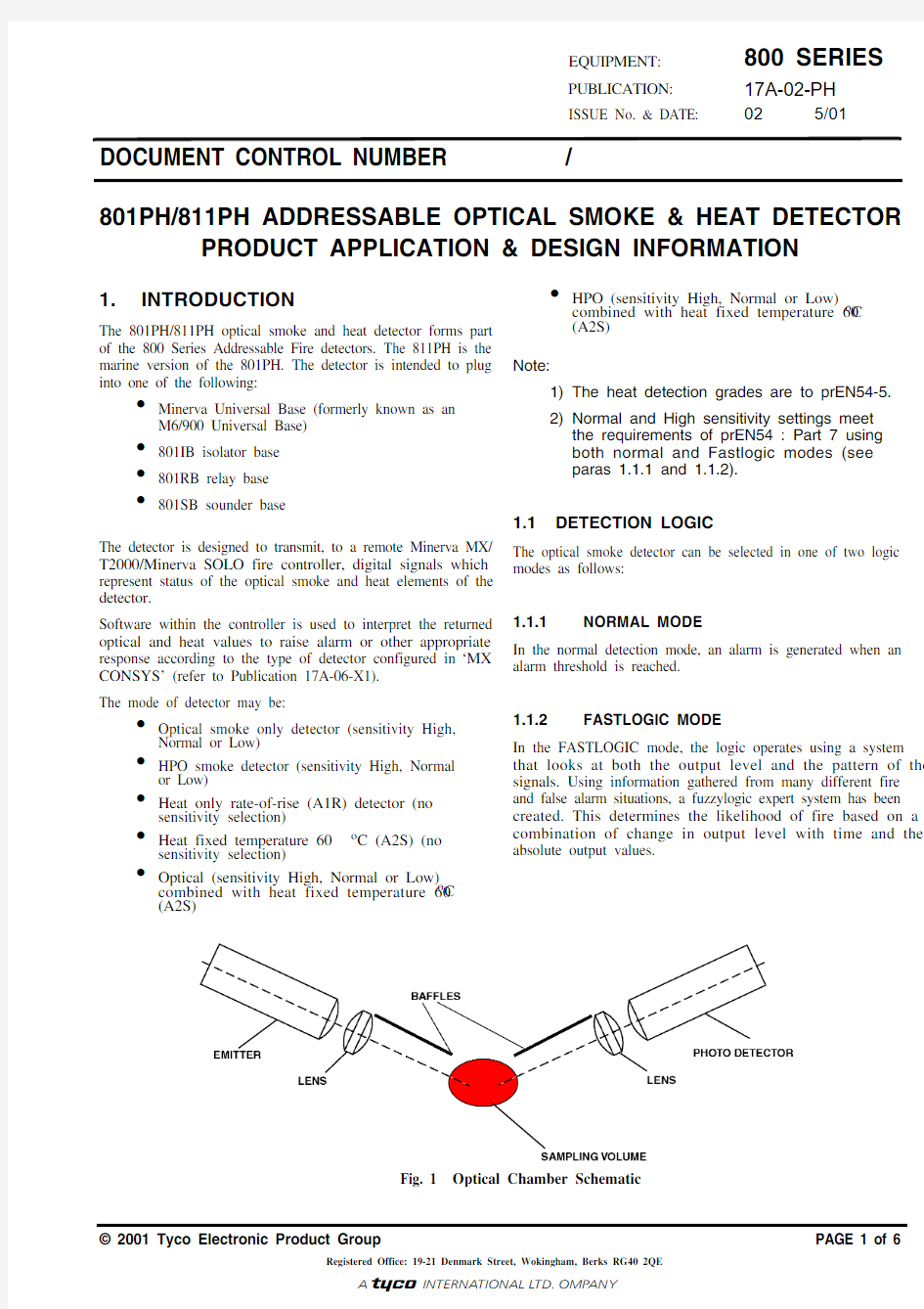
Fig. 1Optical Chamber Schematic
1.2DAY/NIGHT SWITCHING
Two modes of detector operation are selectable from the list of possible modes as follows:
?‘Normal’ mode, ie night time operation in
which the detector will be evaluated most of
the time.
?‘Day’ mode in which the detector can be
switched under certain circumstances, eg
during daytime when the building is
occupied with people being able to detect a
fire manually.Switching to the ‘daytime’
mode can be done either by user action
(pressing the DAY/NI GHT switch on the
controller), event or time driven.
1.3SENSITIVITY SWITCHING
n addition to mode switching, the sensitivity can be changed within the actual mode.This can be done either by user action or be event or time driven (eg, day/night switching).Changing the sensitivity is done by shifting the sensitivity by one level up or down.
2.OPERATING PRINCIPLE
The 801PH/811PH operates by sensing the optical scatter from smoke particles generated in a fire.While the optical scatter detector can give good detection performance for the majority of fires, some fast burning fires produce little visible smoke and some produce very black smoke, neither of which are easily detected by the optical scatter detector.(Such fires are represented in prEN54-7 by Polyurethane and Heptane type fires respectively).These fires do however produce high heat outputs with an associated rise in air temperature.
The detector has been designed to offer improved detection of such fires by detecting the rapid rate-of-rise of air temperature and under these conditions increasing the smoke detection sensitivity.This gives an earlier detection of such fires and a broader detection capability than a standard detector.
The 801PH/811PH detector has two sensing systems as follows:
?An optical chamber with associated
electronics to measure the presence of
smoke by light scatter.
? A thermistor with its associated electronics
to detect the presence of hot air draughts or
high temperatures.
2.1OPTICAL SYSTEM
The 801PH/811PH detects visible particles produced in fires by using the light scattering properties of the particles.The d e t e c to r u s e s th e o p ti c a l a r r a n g e m e n t s h ow n diagrammatically in Fig. 1.The optical system consists of an infra-red emitter and receiver, with a lens in front of each, so arranged that their optical axes cross in the sampling volume.The emitter, with its lens, produces a narrow beam of light which is prevented from reaching the receiver by the baffles.When smoke is present in the sampling volume a proportion of the light is scattered, some of which reaches the receiver.For a given type of smoke, the light reaching the photodetector is proportional to the smoke density.
2.2SELF-TEST
The ‘Self-Test’ facility flashes an LED into the receiver to produce an output above the alarm threshold to signal an alarm condition when requested by the controller.
2.3FEATURES OF MEASURING
CHAMBER
The 801PH/811PH uses vertical chevrons to exclude ambient light.
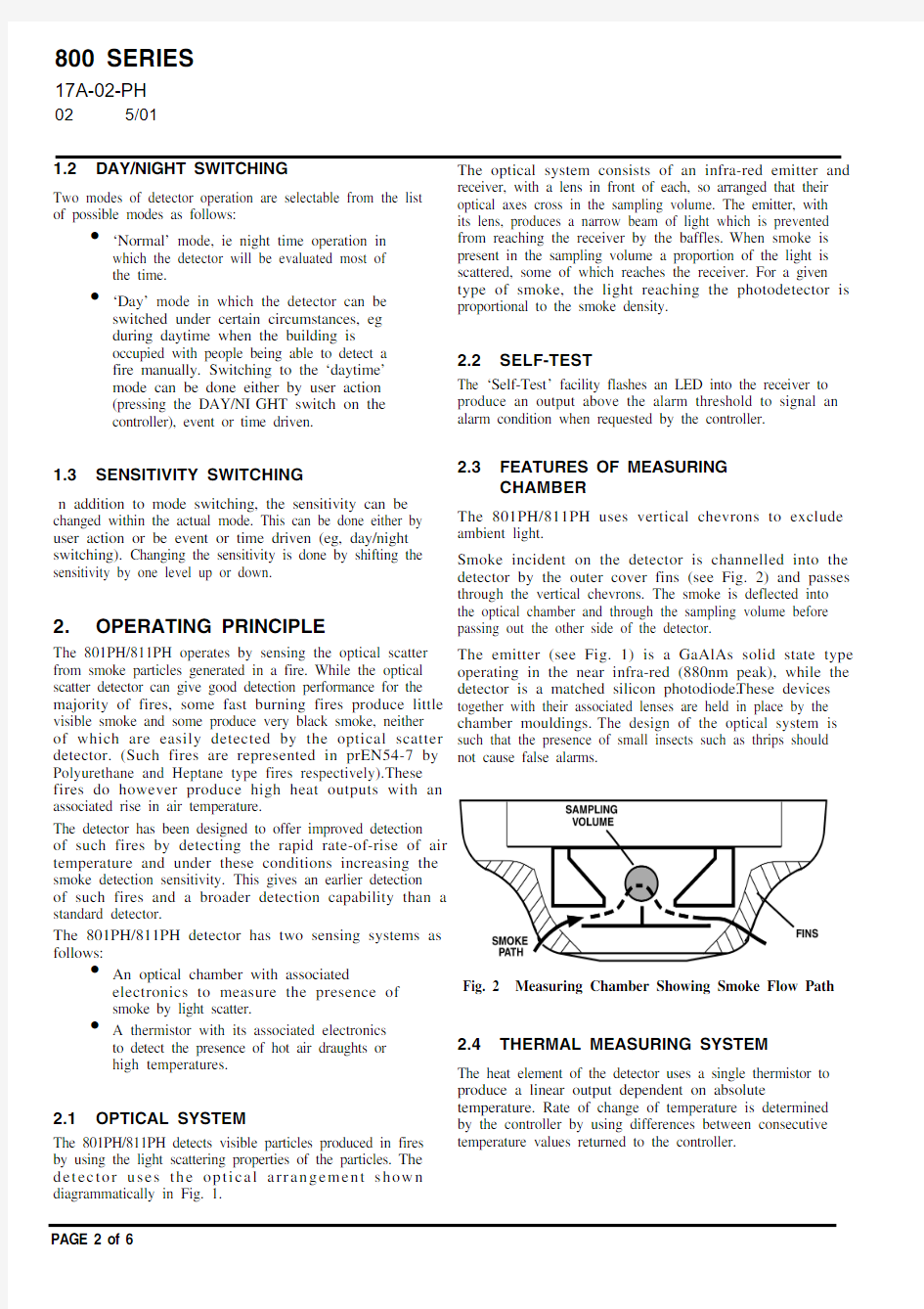
Smoke incident on the detector is channelled into the detector by the outer cover fins (see Fig. 2) and passes through the vertical chevrons.The smoke is deflected into the optical chamber and through the sampling volume before passing out the other side of the detector.
The emitter (see Fig. 1) is a GaAlAs solid state type operating in the near infra-red (880nm peak), while the detector is a matched silicon photodiode.These devices together with their associated lenses are held in place by the chamber mouldings.The design of the optical system is such that the presence of small insects such as thrips should not cause false alarms.
2.4THERMAL MEASURING SYSTEM
The heat element of the detector uses a single thermistor to produce a linear output dependent on absolute temperature.Rate of change of temperature is determined by the controller by using differences between consecutive
temperature values returned to the controller.
Fig. 2Measuring Chamber Showing Smoke Flow Path
? 2001 Tyco Electronic Product Group
PAGE 3 of 6
Registered Office: 19-21 Denmark Street, Wokingham, Berks RG40 2QE
Fig. 3Simplified Block Schematic of detector
2.5
CIRCUIT DESCRIPTIONS
2.5.1
OPTICAL
The emitter is only pulsed every time the detector is polled from the controller, this is to reduce quiescent current.The optical pulse signal as received by the photodetector (a signal proportional to the scatter within the optical chamber)is fed to the ‘Optical ASIC ’.The optical ASIC amplifies the analogue signal which is fed to an analogue input on the common circuit.2.5.2
HEAT
A simplified block schematic of the circuit is given in Fig. 3.The negative temperature coefficient thermistor produces a linear analogue output which is fed to an analogue input on the common circuit.2.5.3
COMMON CIRCUIT
Refer to Fig. 3.
Communications between the controller and detector uses the Frequency Shift Keying (FSK) method.
The ‘Discrimination Circuit ’ filters the FSK signal from the +ve line voltage and converts it to a digital square wave input for the ‘Communications ASIC ’.
The ‘Communications ASIC ’ decodes the signal and when its own address is decoded, the analogue inputs received from the optical and heat sensing elements are converted to corresponding digital values.These digital values are then passed to the ‘Tx Driver Circuit/Current Sink ’ which applies them to the +ve line for transmission to the controller.
The Common Circuit is also used to:
?Control Sounder and Relay bases via the ‘Functional Base nterface Circuit ’ from controller commands.
?
Control the operation of the Remote LED via the ‘Remote LED Circuit ’ from controller commands.
2.6WIRING
Loop cabling is connected to base terminals L (-ve) and L1(+ve). A drive is provided for a remote indicator connected between loop positive and terminal R.Terminal L2(analogue output) is for use with functional sounder and relay bases.
3.
MECHANICAL CONSTRUCTION
The major components of the detector are:
?Body Assembly ?Printed Circuit ?Optical Chamber ?Optical Chamber Cover ?Thermistor ?Light Pipe ?
Outer Cover
3.1
ASSEMBLY
The body assembly consists of a plastic moulding which has four embedded detector contacts which align with contacts in the 801B base.The moulding incorporates securing features to retain the detector in the base.
The PCB is clipped to the body by four spring contacts.These contacts act as a mechanical fixture during assembly and provide electrical contact between the contacts and the PCB.
The chamber cover is clipped to the body over the optical chamber ensuring the thermistor protrudes through the cover.The light pipe is slotted into the chamber cover.
Finally, the outer cover is clipped to the body.
Fig. 4
Sectioned and Top View of the Detector
Fig. 5Overall Dimensions of 801PH detector
109
43
4.
TECHNICAL SPECIFICATION
4.1
MECHANICAL
Dimensions
The overall dimensions are shown in Fig. 5 (less base).Materials
Body, cover, and closure:FR110 ‘BAYBLEND ’flame retardant.
Weight
Detector:
0.076kg Detector + Base:
0.14kg
4.2ENVIRONMENTAL
Temperature Operating: -25o C to +70o C Storage: -40o C to +80o C Relative Humidity:95% (non-condensing)Shock:Vibration:prEN54 Pts. 5 and 7Impact:Corrosion:
prEN54 Pts. 5 and 7
The detectors comply with Lloyd ’s Register Test Specification Number 1 (1996). Environmental Category ENV5.
4.3
ELECTROMAGNETIC COMPATIBILITY
The detector complies with the following:
Product family standard EN50130-4 in respect of Conducted Disturbances, Radiated Immunity,
Electrostatic Discharge, Fast Transients and Slow High Energy
EN50081-1 for Emissions
4.4
ELECTRICAL CHARACTERISTICS
The following characteristics (Table 1) apply at 25o C and nominal supply voltage of 37.5V unless otherwise specified.
* No remote indicator fitted
Characteristic
Min.Typ.Max.Unit Loop Voltage 20.0-40V
Quiescent Current -275305μA Alarm Current*
3
3.3
mA
Table 1:
Electrical Characteristics
? 2001 Tyco Electronic Product Group
PAGE 5 of 6
Registered Office: 19-21 Denmark Street, Wokingham, Berks RG40 2QE
4.5PERFORMANCE CHARACTERISTICS
The 801PH detector, with its base, forms an addressable detector which transmits signals representing the detector digital current levels to a remote control unit.The control unit evaluates these signals against pre-determined criteria and decides when an alarm condition has occurred.The information given below therefore relates to the performance of the 801PH as a transducer only, since the system alarm response is determined by the control unit.4.5.1
RESPONSE TO SMOKE
The response of an optical smoke detector is normally measured with reference to the obscuration produced by smoke.Obscuration is measured in percent per metre, or in dB per metre.The latter unit is used in prEN54-7 and is designated ‘m ’.
Unfortunately, there is no fixed relationship between optical scattering and obscuration, the ratio between them being dependent on the type of smoke.For convenience, ‘grey ’smoke is normally used but white and black smokes give
more or less scattered light respectively for a given obscuration level.
The working of the 801PH is a linear function of obscuration for a given type of smoke as shown graphically in Fig. 6.
Fig. 6
4.5.2
RESPONSE TO RATE OF CHANGE OF TEMPERATURE (HPO)
The detector will not be enhanced by slow rates of change o f te m pe ra tu r e o r n ega t ive r a te s o f c h a n g e o f temperature.The detector is designed to detect sudden horizontal draughts of hot air produced by fast burning fires.The enhancement switching point has been set to allow the detection of TF1 type fires.
5.
DETECTOR IDENTIFICATION
The detector is identified by the logo label colouring as shown in Fig. 7.
6.DETECTOR ADDRESS
The loop address of the detector is held in internal E 2PROM which is programmed either from the controller or by a Field Address Programmer.
7.ADDRESS FLAG
Refer to Fig. 8.The address flag is used to identify the address and zone of the detector.The address flags are supplied in one of two packs (address 1 - 127 or 128 - 255,with a different colour for each loop) and are ordered separately from the detector.The address flag is fitted to the bottom of the detector.When the detector is fitted to the
base and turned until fully located ’ the address flag is then transferred to the base.If the detector is removed from the base, the address flag remains with the base.
Fig. 7Detector Identification
GREEN
WHITE
COMPANY IDENTIFIER
8.ORDERING INFORMATION
801PH Optical Smoke + Heat detector:516.800.500811PH Optical Smoke + Heat detector:516.800.507Minerva Universal Base:517.050.001Address Flag Labels - Loop A (White)
516.800.931Address Flag Labels - Loop B (Yellow)
516.800.932Address Flag Labels - Loop C (Purple)
516.800.933Address Flag Labels - Loop D (Green)
516.800.934
JM/cb 23rd
may 2001
Fig. 8Fitting Address Label Carrier