MAX9812
General Description
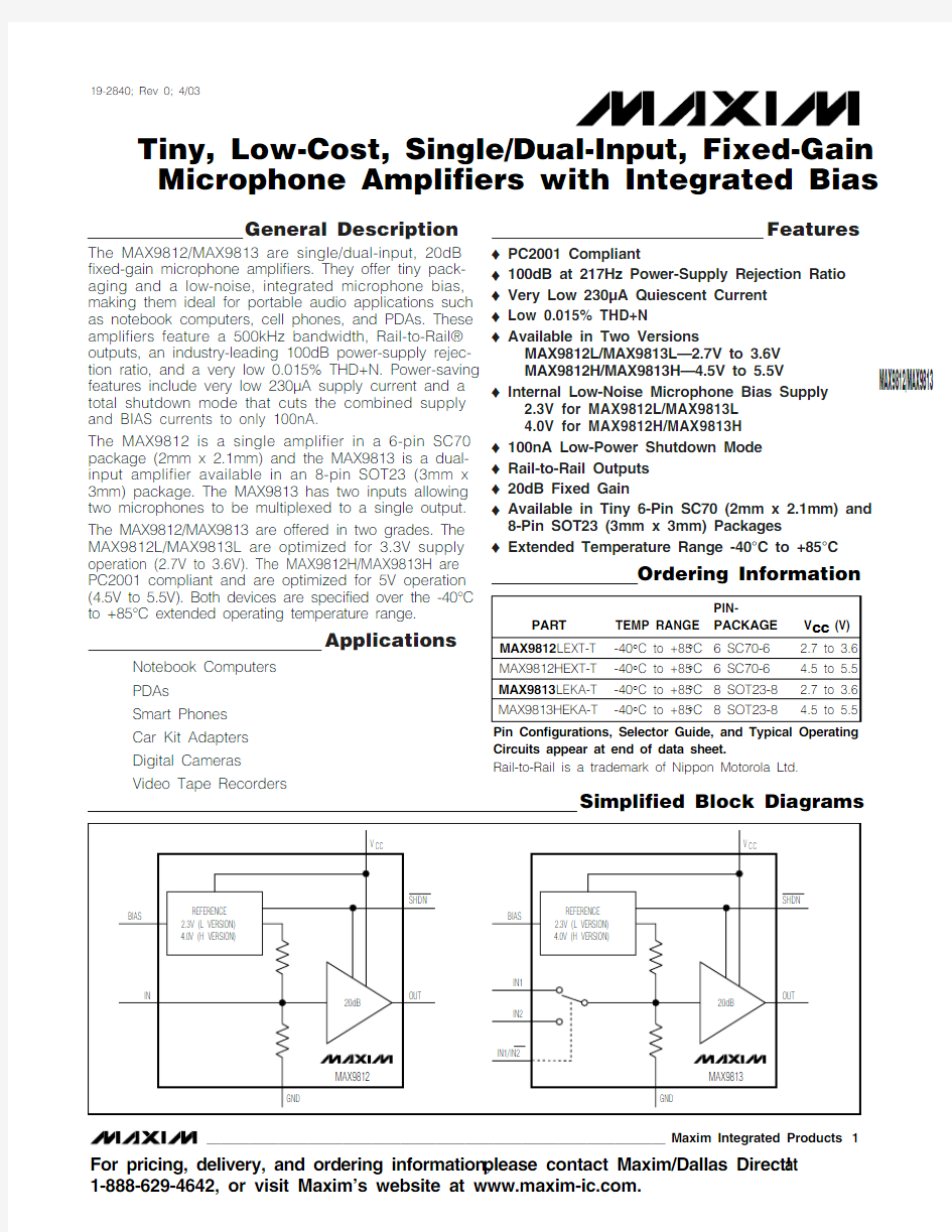
The MAX9812/MAX9813 are single/dual-input, 20dB fixed-gain microphone amplifiers. They offer tiny pack-aging and a low-noise, integrated microphone bias,making them ideal for portable audio applications such as notebook computers, cell phones, and PDAs. These amplifiers feature a 500kHz bandwidth, Rail-to-Rail?outputs, an industry-leading 100dB power-supply rejec-tion ratio, and a very low 0.015% THD+N. Power-saving features include very low 230μA supply current and a total shutdown mode that cuts the combined supply and BIAS currents to only 100nA.
The MAX9812 is a single amplifier in a 6-pin SC70package (2mm x 2.1mm) and the MAX9813 is a dual-input amplifier available in an 8-pin SOT23 (3mm x 3mm) package. The MAX9813 has two inputs allowing two microphones to be multiplexed to a single output. The MAX9812/MAX9813 are offered in two grades. The MAX9812L/MAX9813L are optimized for 3.3V supply operation (2.7V to 3.6V). The MAX9812H/MAX9813H are PC2001 compliant and are optimized for 5V operation (4.5V to 5.5V). Both devices are specified over the -40°C to +85°C extended operating temperature range.
Applications
Notebook Computers PDAs Smart Phones Car Kit Adapters Digital Cameras Video Tape Recorders
Features
o PC2001 Compliant
o 100dB at 217Hz Power-Supply Rejection Ratio o Very Low 230μA Quiescent Current o Low 0.015% THD+N
o Available in Two Versions
MAX9812L/MAX9813L—2.7V to 3.6V MAX9812H/MAX9813H—4.5V to 5.5V
o Internal Low-Noise Microphone Bias Supply 2.3V for MAX9812L/MAX9813L 4.0V for MAX9812H/MAX9813H o 100nA Low-Power Shutdown Mode o Rail-to-Rail Outputs o 20dB Fixed Gain
o Available in Tiny 6-Pin SC70 (2mm x 2.1mm) and 8-Pin SOT23 (3mm x 3mm) Packages
o
Extended Temperature Range -40°C to +85°C
MAX9812/MAX9813
Tiny, Low-Cost, Single/Dual-Input, Fixed-Gain Microphone Amplifiers with Integrated Bias
________________________________________________________________Maxim Integrated Products 1
Ordering Information
19-2840; Rev 0; 4/03
For pricing, delivery, and ordering information,please contact Maxim/Dallas Direct!at 1-888-629-4642, or visit Maxim’s website at https://www.360docs.net/doc/436956569.html,.
Pin Configurations, Selector Guide, and Typical Operating Circuits appear at end of data sheet.
Simplified Block Diagrams
Rail-to-Rail is a trademark of Nippon Motorola Ltd.
M A X 9812/M A X 9813
Tiny, Low-Cost, Single/Dual-Input, Fixed-Gain Microphone Amplifiers with Integrated Bias 2_______________________________________________________________________________________
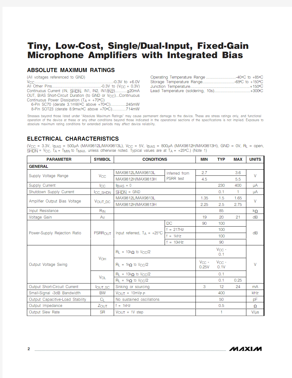
ABSOLUTE MAXIMUM RATINGS
ELECTRICAL CHARACTERISTICS
(V CC = 3.3V, I BIAS = 500μA (MAX9812L/MAX9813L), V CC = 5V, I BIAS = 800μA (MAX9812H/MAX9813H), GND = 0V, R L = open,
Stresses beyond those listed under “Absolute Maximum Ratings” may cause permanent damage to the device. These are stress ratings only, and functional operation of the device at these or any other conditions beyond those indicated in the operational sections of the specifications is not implied. Exposure to absolute maximum rating conditions for extended periods may affect device reliability.
(All voltages referenced to GND)
V CC ........................................................................-0.3V to +6.0V All Other Pins..............................................-0.3V to (V CC + 0.3V)Continuous Current (IN, SHDN , IN1, IN2, IN1/IN2)...........±20mA OUT, BIAS Short-Circuit Duration (to GND or V CC )...Continuous Continuous Power Dissipation (T A = +70°C)
6-Pin SC70 (derate 3.1mW/°C above +70°C)..............245mW 8-Pin SOT23 (derate 8.9mw/°C above +70°C)............714mW
Operating Temperature Range ...........................-40°C to +85°C Storage Temperature Range.............................-65°C to +150°C Junction Temperature......................................................+150°C Lead Temperature (soldering, 10s).................................+300°C
MAX9812/MAX9813
Tiny, Low-Cost, Single/Dual-Input, Fixed-Gain Microphone Amplifiers with Integrated Bias
_______________________________________________________________________________________3
ELECTRICAL CHARACTERISTICS (continued)
(V CC = 3.3V, I BIAS = 500μA (MAX9812L/MAX9813L), V CC = 5V, I BIAS = 800μA (MAX9812H/MAX9813H), GND = 0V, R L = open,
M A X 9812/M A X 9813
Tiny, Low-Cost, Single/Dual-Input, Fixed-Gain Microphone Amplifiers with Integrated Bias 4_______________________________________________________________________________________
Typical Operating Characteristics
(V CC = 3.3V (MAX9812L/MAX9813L), V CC = 5V (MAX9812H/MAX9813H), GND = 0V, R L = 10k ?to V CC /2, SHDN = V CC , T A = +25°C,unless otherwise noted.)
-20
0-102010304010
1k 10k 100100k 1M 10M
GAIN vs. FREQUENCY
FREQUENCY (Hz)
O U T P U T V O L T A G E G A I N (d B )
POWER-SUPPLY REJECTION RATIO
vs. FREQUENCY
FREQUENCY (Hz)
P S R R (d B )
10k 1k 100
10
100k -150
-80-90-100-110-120-130-140-60-70-40-50-30-10-200POWER-SUPPLY REJECTION RATIO (V CC TO BIAS) vs. FREQUENCY
FREQUENCY (Hz)
P S R R (V C C T O B I A S ) (d B )
10k 1k 100-90-80-70-60-50-40-30-20-100
-100
10100k
200
210205220215230225235245240250-40-10
5
20
-2535
50
65
80
SUPPLY CURRENT vs. TEMPERATURE
TEMPERATURE (°C)
S U P P L Y C U R R E N T (μA )
100
1401201801602202002402802603002.0 2.8 3.2 3.62.4 4.0 4.4 4.8 5.65.2 6.0
SUPPLY CURRENT vs. SUPPLY VOLTAGE
SUPPLY VOLTAGE (V)
S U P P L Y C U R R E N T (μA )
0.05
0.070.060.090.080.110.100.120.140.130.15-40-10520-2535506580
SHUTDOWN SUPPLY CURRENT
vs. TEMPERATURE
M A X 9812 t o c 06
TEMPERATURE (°C)
S H U T D O W N S U P P L Y C U R R E N T (μA )2.27
2.282.292.302.312.322.33-40-10
-255
20
35
5065
80
V BIAS vs. TEMPERATURE
TEMPERATURE (°C)
V B I A S (L V E R S I O N ) (V ) 3.973.983.994.004.01
4.02
4.033.96
V B I A S (H V E R S I O N ) (V )
2.2997
2.2998
2.2999
2.3000
2.3001
2.3002
0.8 1.00.40.60.2 1.2 1.4 1.6 1.8 2.0
V BIAS vs. I BIAS
I BIAS (mA)
V B I A S (L V E R S I O N ) (V )
3.9998
3.9999
4.0000
4.0001
4.0002
V B I A S (H V E R S I O N ) (V )
MAX9812/MAX9813
Tiny, Low-Cost, Single/Dual-Input, Fixed-Gain Microphone Amplifiers with Integrated Bias
_______________________________________________________________________________________5
TOTAL HARMONIC DISTORTION PLUS NOISE
vs. OUTPUT AMPLITUDE
OUTPUT AMPLITUDE (V RMS )
T H D +N (%)
1.81.61.41.21.00.80.60.40.20.01
0.1
110
0.001
2.0
TOTAL HARMONIC DISTORTION PLUS NOISE
vs. OUTPUT AMPLITUDE
OUTPUT AMPLITUDE (V RMS )
T H D +N (%)
1.0
0.5
0.01
0.1
1100
10
0.001
1.5
100
50
30
701010
10k
100k
FREQUENCY (Hz)
I N P U T -R E F E R R E D N O I S E (n V /√H z )
100
INPUT-REFERRED NOISE vs. FREQUENCY
1k BIAS NOISE vs. FREQUENCY
M A X 9812 t o c 13
FREQUENCY (Hz)
B I A S N O I S E (n V /√H z )
10k
1k 100
100
1000
10,0001010
100k
OFF-ISOLATION vs. FREQUENCY
FREQUENCY (Hz)
C R O S S T A L K (d B )
10k
1k 100
-90
-80-70-60-50-40-30-20-10010
-100
10
100k
Typical Operating Characteristics (continued)
(V CC = 3.3V (MAX9812L/MAX9813L), V CC = 5V (MAX9812H/MAX9813H), GND = 0V, R L
= 10k ?to V CC /2, SHDN = V CC , T A = +25°C,unless otherwise noted.)
TOTAL HARMONIC DISTORTION PLUS NOISE
vs. FREQUENCY
FREQUENCY (Hz)
T H D +N (%)
10k
1k 100
0.01
0.11
0.001
10
100k
M A X 9812/M A X 9813
Tiny, Low-Cost, Single/Dual-Input, Fixed-Gain Microphone Amplifiers with Integrated Bias 6
_______________________________________________________________________________________
2μs/div
OUTPUT OVERDRIVEN
OUT 1V/div
MAX9812 toc19
IN
500mV/div
Typical Operating Characteristics (continued)
(V CC = 3.3V (MAX9812L/MAX9813L), V CC = 5V (MAX9812H/MAX9813H), GND = 0V, R L = 10k ?to V CC /2, SHDN = V CC , T A = +25°C,unless otherwise noted.)
1ms/div OUT-OF-SHUTDOWN WAVEFORM
INPUT FLOATING
MAX9812 toc17
OUT 2V/div
BIAS 2V/div SHDN 2V/div
100μs/div
MAX9813
SWITCHING BETWEEN TWO INPUTS
1V/div
2V/div
OUT
IN1/IN2
IN2 = 200mV P-P AT 20kHz IN1 = 100mV P-P AT 10kHz
1μs/div
SMALL-SIGNAL PULSE RESPONSE
(R L = OPEN, C L = 10pF)
IN 5mV/div MAX9812 toc15OUT 50mV/div 2μs/div
LARGE-SIGNAL PULSE RESPONSE
(R L = OPEN, C L = 10pF)
IN
100mV/div
MAX9812 toc16
OUT 1V/div 0V
MAX9812/MAX9813
Tiny, Low-Cost, Single/Dual-Input, Fixed-Gain Microphone Amplifiers with Integrated Bias
_______________________________________________________________________________________7
Pin Description
M A X 9812/M A X 9813
Tiny, Low-Cost, Single/Dual-Input, Fixed-Gain Microphone Amplifiers with Integrated Bias 8_______________________________________________________________________________________
Figure 1. Typical Application Circuit
MAX9812/MAX9813
Tiny, Low-Cost, Single/Dual-Input, Fixed-Gain Microphone Amplifiers with Integrated Bias
_______________________________________________________________________________________9
Chip Information
MAX9812 TRANSISTOR COUNT: 264MAX9813 TRANSISTOR COUNT: 269PROCESS: BiCMOS
Typical Operating Circuits
Pin Configurations
M A X 9812/M A X 9813
Tiny, Low-Cost, Single/Dual-Input, Fixed-Gain Microphone Amplifiers with Integrated Bias 10______________________________________________________________________________________
Package Information
(The package drawing(s) in this data sheet may not reflect the most current specifications. For the latest package outline information go to https://www.360docs.net/doc/436956569.html,/packages .)
MAX9812/MAX9813
Tiny, Low-Cost, Single/Dual-Input, Fixed-Gain Microphone Amplifiers with Integrated Bias
Maxi m cannot assume responsi bi li ty for use of any ci rcui try other than ci rcui try enti rely embodi ed i n a Maxi m product. No ci rcui t patent li censes are implied. Maxim reserves the right to change the circuitry and specifications without notice at any time.
Maxim Integrated Products, 120 San Gabriel Drive, Sunnyvale, CA 94086 408-737-7600 ____________________11?2003 Maxim Integrated Products
Printed USA
is a registered trademark of Maxim Integrated Products.
Package Information (continued)
(The package drawing(s) in this data sheet may not reflect the most current specifications. For the latest package outline information go to https://www.360docs.net/doc/436956569.html,/packages .)