Using the I-N-C-A Constraint Model as a Shared Representation of Intentions for Emergency R
Using the
Gerhard Wickler AIAI, University of Edinburgh Edinburgh, Scotland, UK g.wickler@https://www.360docs.net/doc/4815489518.html,
Austin Tate
AIAI, University of Edinburgh
Edinburgh, Scotland, UK
a.tate@https://www.360docs.net/doc/4815489518.html,
Stephen Potter
AIAI, University of Edinburgh
Edinburgh, Scotland, UK
s.potter@https://www.360docs.net/doc/4815489518.html,
ABSTRACT
The aim of this paper is to describe the I-X system with its underlying representation:
I.2.4 [Artificial Intelligence]: Knowledge Representation Formalisms and Methods – Representation languages;
I.2.8 [Artificial Intelligence]: Problem Solving, Control Methods, and Search – Plan execution, formation, and generation;
I.2.11 [Artificial Intelligence]: Distributed Artificial Intelligence – Multiagent systems.
General Terms
Human Factors, Standardization, Languages, Theory. Keywords
HTN planning, agent capabilities and coordination, agent modelling.
1INTRODUCTION
There are a number of tools available that help people organize their work. One of these is provided with virtually every organizer, be it electronic or paper-based: the “to-do” list. This is because people are not very good at remembering long lists of potentially unrelated tasks. Writing these tasks down and ticking them off when they have been done is a simple means of ensuring that everything that needs to be done does get done, or at least, that a quick overview of unaccomplished tasks is available. In responding to an emergency this is vital, and the larger the emergency is, the more tasks need to be managed.
The I-X system provides the functionality of a to-do list and thus, it is a useful tool when it comes to organizing the response to an emergency. The idea of using a to-do list as a basis for a distributed task manager is not new [9]. However, I-X goes well beyond this metaphor and provides a number of useful extensions that facilitate the finding and adaptation of a complete and efficient course of action.
The remainder of this paper is organized as follows: Firstly, we will describe the model underlying the whole system and approach:
2USING I-X PROCESS PANELS
I-X Process Panels constitute the user interface to the I-X system. They more or less directly reflect the ontology underlying the whole I-X system, the
2.1The
In
etc. They also contain “Nodes” (activities in a process, or parts of a physical product) which may have parts called sub-nodes making up a hierarchical description of the process or product. The nodes are related by a set of detailed “Constraints” of various kinds. Finally there can be “Annotations” related to the processes or products, which provide rationale, information and other useful descriptions.
?for automatic and mixed-initiative generation and manipulation of plans and other synthesized artifacts and
to act as an ontology to underpin such use;
?as a common basis for human and system communication about plans and other synthesized artifacts;
?as a target for principled and reliable acquisition of knowledge about synthesized artifacts such as plans,
process models and process product information;
?to support formal reasoning about plans and other synthesized artifacts.
These cover both formal and practical requirements and encompass the requirements for use by both human and computer-based planning and design systems.
2.1.1Issues
The issues in the representation may give the outstanding questions to be handled and can represent decisions yet to be taken on objectives to be satisfied, ways in which to satisfy them, questions raised as a result of analysis, etc. Initially, an
In work on I-X until recently, the issues had a task or activity orientation to them, being mostly concerned with actionable items referring to the process underway – i.e., actions in the process space. This has caused confusion with uses of I-X for planning tasks, where activities also appear as “nodes”. This is now not felt to be appropriate, and as an experiment we are adopting the gIBIS orientation of expressing these issues as questions to be considered [15,3]. This is advocated by the Questions – Options – Criteria approach [10] – itself used for rationale capture for plans and plan schema libraries in earlier work [12] and similar to the mapping approaches used in Compendium [16].
2.1.2Nodes
The nodes in the specifications describe components that are to be included in the design. Nodes can themselves be artifacts that can have their own structure with sub-nodes and other
2.1.3Constraints
The constraints restrict the relationships between the nodes to describe only those artifacts within the design space that meet the objectives. The constraints may be split into “critical constraints” and “auxiliary constraints” depending on whether some constraint managers (solvers) can return them as “maybe” answers to indicate that the constraint being added to the model is okay so long as other critical constraints are imposed by other constraint managers. The maybe answer is expressed as a disjunction of conjunctions of such critical or shared constraints. More details on the “yes/no/maybe” constraint management approach used in I-X and the earlier O-Plan systems are available in [21].
The choices of which constraints are considered critical and which are considered as auxiliary are decisions for an application of I-X and specific decisions on how to split the management of constraints within such an application. It is not pre-determined for all applications. A temporal activity-based planner would normally have object/variable constraints (equality and inequality of objects) and some temporal constraints (maybe just the simple before {time-point1, time-point-2} constraint) as the critical constraints. But, for example in a 3D design or a configuration application, object/variable and some other critical constraints (possibly spatial constraints) might be chosen. It depends on the nature of what is communicated between constraint managers in the application of the I-X architecture.
2.1.4Annotations
The annotations add additional human-centric information or design and decision rationale to the description of the artifact. This can be of assistance in making use of products such as designs or plans created using this approach by helping guide the choice of alternatives should changes be required.
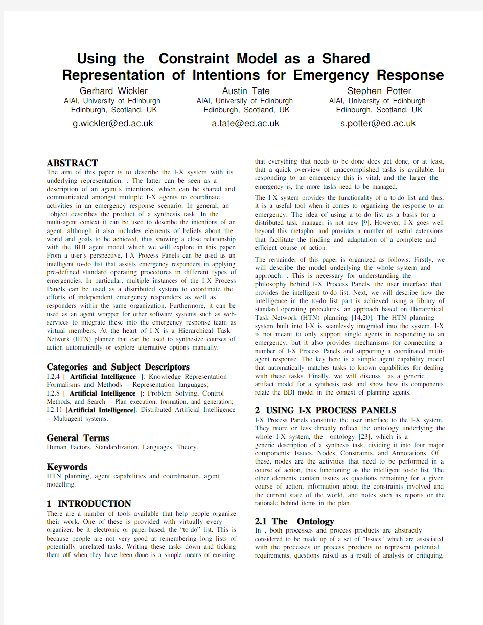
2.2I-X Process Panels: Intelligent To-Do Lists The user interface to the I-X system, the I-X Process Panel, shows four main parts that reflect the four components of the
“State”, and “Annotations”, as shown in figure 1.
Figure 1. An I-X Process Panel, shown here addressing a
simulated oil spill incident.
In the case of the artifact to be synthesized being a course of action, the nodes that will eventually make up the artifact are activities, and these play the central role in the view of an I-X panel as an intelligent to-do list. Users can add an informal
description of a task to be accomplished to the activities section of the panel where it will appear as the description of that activity. Each activity consists of four parts listed in the four columns of the activities part of the panel:
?Description: This can be an informal description of a task such as “do this” or it can be a more formal pattern
consisting of an activity name (verb) followed by a list of
parameters such as:
(deploy ?team-type)
where the words preceded by a question mark are
variables that need to be bound before the task can be
dealt with.
?Annotation: This can be used to add arbitrary pieces of information to a specific activity.
?Priority: This defines the priority of the activity. Possible values are Highest, High, Normal, Low, or Lowest.
?Action: This field contains a menu that gives the various options that are available to deal with the activity.
It is the last field that allows the user to mark the task as “Done”, which corresponds to ticking off an item in a to-do list. Other options that are always available are “No action”, the default value until the task has been dealt with, or “N/A” if the activity does not make sense and is “not applicable” in the current context.
The entries in the action menu related to an activity are determined by the activity handlers. These are modules that can be plugged into the I-X system and define ways in which activities can be dealt with. If an activity handler matches an activity it can add one or more entries to the according action menu. The most commonly used activity handler in the context of HTN planning adds “Expand” items to this menu, and this is the point where the to-do list becomes intelligent.
Instead of just being able to tick off an activity, users can use the knowledge in a library of standard operating procedures to break an activity down into sub-activities that, when all performed, accomplish the higher-level task. Of course, sub-activities can themselves be broken down further until a level of primitive actions is reached, at which point the library of procedures no longer contains any refinements that mach the activities. This mechanism supports the user in two ways:
?The library of standard operating procedures may contain
a number of different refinements that all match the
present activity. All of the applicable procedures are
added to the action menu by the activity handler, thus
giving the user a comprehensive and quick overview of all
the known standard procedures available to deal with this
task.
?When a refinement for an activity is chosen, the I-X Process Panel shows all the sub-activities as new items in
the to-do list. This ensures that users do not forget to
include sub-activities, a common problem especially for
infrequently applied procedures.
Both of these problems become only more severe when the user is under time pressure and lives depend on the decisions taken. Note that the intelligence of the to-do list comes in through the underlying HTN planner that finds applicable refinements in the library and, on demand, can complete a plan to perform a given task automatically, propagating all constraints as it does so. Equally important, however, is the knowledge contained in the library of standard operating procedures.
2.3Other Features
As activities are the nodes that make up a course of action, it is only natural that the activity part of the I-X Process Panel forms the centre of attention for our view of I-X as an intelligent to-do list. In fact, we have implemented a cut-down interface called Post-IX which only shows this part of the panel (and so provides a minimal or ‘entry level’ interface to the system). We shall now briefly describe the other parts of a panel and how they are used. World state constraints are used to describe the current state of the world. Essentially, these are a state-variable representation of the form “pattern = value” allowing the user to describe arbitrary features of the world state. They are displayed in the I-X Process Panel in the constraints section. However, it is not expected that users will find this list of facts about the world style representation very useful. Thus, I-X allows for the registration of world state viewers that can be plugged into the system. For example, BBN Openmap [11] has been used in a number of applications to provide a 2D world map with various features. Most importantly, it can be automatically synchronized with the world state constraints such that icons in the map always represent current positions of the entities they represent. Constraints are propagated and evaluated by constraint managers that are plugged into the I-X system.
Issues can be seen as a meta to-do list: instead of listing items that need to be done to deal with an emergency in the real world, they list the questions or outstanding items that need to be dealt with to make the current course of action complete and consistent. Often, these will be flaws in the current plan, but they can also be opportunities that present themselves, or simply facts that need to be verified to ensure a plan is viable. Issues can be either formal, in which case registered issue handlers can be used to deal with them just like activity handlers deal with activities, or they can be informal.
Annotations are used for arbitrary comments about the course of action as a whole, stored as “keyword = value” patterns.
3STANDARD OPERATING PROCEDURES
As outlined above, standard operating procedures describe the knowledge underlying the intelligent to-do list. The formalism is based on refinements used in HTN planning and will be explained next. However, users are not expected to learn this formalism, but they can use a domain editor and its graphical user interface to define the library of procedures.
3.1Activity Refinements in HTN Planning What are known as standard operating procedures to domain experts are called methods in HTN planning [5]. Methods formally describe how a task can be broken down into sub-tasks. The definition of a method consists of four main parts:
?Task pattern: an expression describing the task that can be accomplished with this method;
? Name: the name of this method (there may be several for
the same task); ? Constraints: a set of constraints (e.g. on the world state)
that must hold for this method to be applicable; and ? Network: a description of the sub-tasks into which this
method refines the given task. The task pattern of a method is used for matching methods to items in the activity list. If the task pattern matches the activity the method will appear in the action menu of the activity in the panel as a possible expansion. This is also where the name of the method will be used: the menu displays an entry “Expand using
any given time.
Figure 2. The I-X Domain Editor, here shown modelling an oil
spill response standard operating procedure.
3.2 The I-X Domain Editor
Figure 2 shows an example of the I-X Domain Editor for defining standard operating procedures. The panel on the left lists all the currently defined procedures by name, and the task pattern they match. One, called “Oil Spill Response (General)”, is shown being edited. There are a number of views available to edit a refinement. The one shown is the graphical view which shows all the direct sub-tasks with their begin and end time points. Arrows between these activities indicate temporal ordering constraints, for example, the activity “Control source of spill ” cannot be started before “Ensure safety of public and response personnel ” has been completed. However, the activities “Control source of spill ” and “Manage coordinated response effort ” can then be
performed in parallel. Other views show the conditions and effects that can be defined for refinements.
4
AGENT COORDINATION WITH MULTIPLE PANELS
So far we have described I-X as a tool for assisting a single person in organizing and executing the response to an emergency. However, I-X is also a tool that supports the coordination of the response of multiple agents. I-Space is a tool in which users can register the capabilities of other agents. These capabilities can then be used from an I-X panel through inter-panel communication. Augmented instant messaging can be used to
directly communicate with other responders via their panels.
Figure 3. The I-Space Tool. The agents’ relations to each other governs the nature of interactions between them.
4.1 I-Space
Every I-X panel can be connected to a number of other I-X agents. Each I-X agent represents an agent that can potentially contribute to the course of action taken to respond in an emergency. The I-Space holds the model of the other agents and can be managed with a simple tool as shown in figure 3.
Associated with each agent are one or more communication strategies which define how messages can be sent to this agent. By default, a built-in communication strategy simply sends XML-formatted messages to a given IP-address and socket. Alternatively, a Jabber-strategy [7] is available for using a chat-based mechanism for communication. New communication strategies can be added to communicate with agents implemented using different frameworks.
Usually users will not be concerned with the question of how communication takes place as long as the system can find a way, but more with the relationships between the different agents in the I-Space. Within an organization a hierarchical structure is common, so collaborating agents are usually either superiors or subordinates. They can also be modelled as peers, which is also how agents from other organizations can be described. If the agent to be integrated into the virtual organization is a software agent it is described as a (web-)service. Finally, a generic relation “contact” is available, but it does not specify what exactly the relationship to this agent is.
4.2 Agent Capabilities
At present there is only a relatively simple capability model implemented in I-X. The idea behind this model is that activities
are described by verbs in natural language and thus, a task name can be used as a capability description. Parameter values are currently not used to evaluate a capability. Each agent is associated with a number of capabilities that can be called upon.
In the future it will be possible to use a much more sophisticated model. The problem with more complex representations is often that matching capabilities to tasks can be computationally expensive, and when the number of known capabilities becomes large, this can be a problem, which is why the current model is so simple. On the other hand, capabilities can often only be distinguished by a detailed description. One approach to this trade-off is to provide a representation that is flexible, allowing for a more powerful representation where required, but retaining efficiency if the capability description is simple [24]. Conceptually, the description of a capability is similar to that of an action, which is not surprising as a capability is simply an action that can be performed by some agent. A capability description essentially consists of six components:
?Name: The name of a capability corresponds a the verb that expresses a human-understandable description of the
capability.
?Inputs: These are the objects that are given as parameters to the capability. This may be information needed to
perform the capability, such as the location of a person to
be recovered, objects to be manipulated by the capability,
such as paper to be used in a printing process, or resources
needed to perform the capability.
?Outputs: These are objects created by the capability.
Again, this can be information such as references to
hospitals that may have been sought, or they can be new
objects if the capability manufactures these.
?Input constraints: These are effectively preconditions, consisting of world state constraints that must be true in
the state of the world just before the capability can be
applied. Usually, they will consist of required relations
between the inputs.
?Output constraints: These are similar to effects, consisting of world state constraints that are guaranteed to be
satisfied immediately after the capability has been
applied. Usually, they will consist of provided relations
between the outputs.
?I-O constraints: These cross constraints link up the inputs with the outputs. For example, a prioritization capability
might order a given list of options according to some set
of criterions. A cross constraint, referring to both the
situation before and after the capability has been applied
is necessary to say that the given list of options and the
prioritized list contain the same elements.
This capability model can be used to describe the abilities of real-world agents that ultimately must be deployed to do things, or for software agents that provide information that can be used to guide the activity in the physical world.
4.3Handling Activities through Task
Distribution
From a user’s perspective, task distribution is integrated into the user interface through the “action” menu in the activities part of the panel as just another option available to deal with an activity. The agent relationship is used to determine in which way the activity can be passed to another agent, for example, if the other agent is a subordinate the activity can simply be delegated to the agent.
The capability model is used to filter the options that are listed in the action menu. Currently there is the option of specifying no capabilities for an agent in which case the agent will always be listed. If there is a list of capabilities associated with an agent than these options will only be listed if there is an exact match of the verb capability.
4.4Structured Instant Messaging
Another tool that is widely used for the coordination of efforts in response to an emergency is instant messaging. Like a to-do list, it is very simple and intuitive, but it lacks the formal structure that is needed when the scale of the event that needs to be addressed increases. As for the to-do list, I-X builds on the concept of instant messaging, extending it with the
The structured version can be activated by selecting a message type: issue, activity, constraint or annotation, rather than a simple chat message. An
5I-X/
The idea behind
Two of the properties that are often associated with intelligent agents, amongst others, are that they are situated and that they should exhibit a goal-directed behaviour [13,6]. By “situatedness”
we mean that an agent exists in and acts upon some environment. The agent may be able to sense the environment and therefore hold some beliefs about the state of its environment. A goal is a condition that an agent desires to hold in its world, and if it is not believed to be true already, the agent may be able to act towards achieving. The (goal-directed) behavior of an agent is made up of the actions it performs and their performance is not just by accident but because it intends to do these actions. Beliefs, desires and intentions are the three cognitive primitives that form the basis for the BDI model of agency [19].
At present, the BDI model is probably the most widely used formal model for describing agents.
We model an I-X agent by its current (possibly partial) plan (an
5.1Intentions
Essentially, I-X agents are focused on intentions. In BDI intentions can be considered to be relationships between an agent and a (again, possibly partial) plan; in the I-X ‘world’ a plan is the principal
5.2Beliefs
Beliefs are relationships between agents and statements about the world. An I-X agent maintains only specific beliefs, namely: ‘facts’ about the world that are believed to be true, modeled as constraints in the panel; capability descriptions of other agents in the world; and beliefs about how activities affect the state of the world. Note that the task-centric view of I-X agents means that the knowledge of other agents cannot be easily represented.
5.3Desires
Desires are not explicitly represented in
This shows that the I-X model of agency and the BDI model are quite similar in many respects. The main difference is rooted in the task-centric view taken by the I-X agent. The
6APPLICATIONS
I-X has been applied to a number of application scenarios in the area of emergency response. In this section we survey some of the current applications.
6.1Co-OPR
Personnel recovery teams operate under intense pressure, and must take into account not only hard logistics, but "messy" factors such as the social or political implications of a decision. The Collaborative Operations for Personnel Recovery (Co-OPR) project has developed decision-support for sensemaking in such scenarios, seeking to exploit the complementary strengths of human and machine reasoning [2,22]. Co-OPR integrates the Compendium sensemaking-support tool for real-time information and argument mapping, using the I-X framework to support group activity and collaboration. Both share a common model for dealing with issues, the refinement of options for the activities to be performed, handling constraints and recording other information. The tools span the spectrum, with Compendium being very flexible with few constraints on terminology and content, to the knowledge-based approach of I-X, relying on rich domain models and formal conceptual models (ontologies). In a personnel recovery experimental simulation of a UN peacekeeping operation, with roles played by military planning staff, the Co-OPR tools were judged by external evaluators to have been very effective.
6.2I-Rescue
Siebra and Tate [18] have used I-X to support coordination of rescue agents within the RoboCup Rescue simulation [8]. Strategic, Tactical and Operational levels of decision-making were modelled. Their work shows the integration of an activity-oriented planner with agent collaboration using the
6.3FireGrid
FireGrid [1,4] is a multi-disciplinary UK project to address emergency response in the built environment, where sensor grids in large buildings are linked to faster-than-real-time grid-based simulations of a developing fire, and used to assist human responders to work with the building’s internal response systems and occupants to form a team to deal successfully with the emergency.
The goal of FireGrid is to integrate several technologies, extending them where necessary:
?High Performance Computing applied to the simulation of fire spread and structural integrity.
?Sensors in extreme conditions with adaptive routing algorithms, including input validation and filtering.
?Grid computing including sensor-guided computations, mining of data streams for key events and reactive
priority-based scheduling.
?Command and control using knowledge-based planning techniques with user guidance. The I-X technology is to
be applied at this level.
This command and control element essentially provides an integrating ‘knowledge layer’ to the system. By using
6.4AKT e-Response
The Advanced Knowledge Technologies (AKT – see https://www.360docs.net/doc/4815489518.html,) project is an inter-disciplinary applied research project involving a consortium of five UK universities, concentrating on ‘next generation’ knowledge management tools and techniques, particularly in the context of the semantic web. Emergency response has been chosen as an appropriate task to act as a focus for an integrated demonstrator of a number of AKT technologies.
To this end, we are currently developing a scenario that builds upon the RoboCup-Rescue project “Kobe earthquake” simulator [8]. This project was begun in the wake of the devastating 1995 earthquake to promote applied research to address the inadequacies of the then available IT systems to cope with the demands of the situation. The Kobe simulator was developed to provide a focus to this effort; it models the immediate aftermath of the earthquake, with fires spreading across a district of the city, injured and trapped civilians, and blocked roads hindering response units. Researchers from various fields are invited to participate in the project as they see fit; for instance, the ideas of multi-agent systems researchers can be applied to the coordination of the available (firefighter, police, ambulance) rescue units to attempt to produce an effective response to the disaster. Indeed, this task has become something of a test-piece for researchers interested in agent coordination, with regular competitions to evaluate the relative success (in terms of minimizing overall human and material cost) of different strategies.
However, since the AKT project is focused less on multi-agent systems than on more ‘semantic’ open systems centred on and around humans, for the purposes of the integrated demonstrator we are addressing the task of supporting the high-level strategic response to the emergency. In particular, we aim to provide an ‘intelligence unit’ for the strategy-makers that maintains an overview of the current state of the emergency and the response to it; allows them to access relevant ‘real’ information about the affected locations; lets them explore available options and revise the strategy; and provides a means by which to enact this strategy by relaying orders, reports and other information up and down the chain of command. Since we are looking beyond the simulated world and aim to exploit existing resources and information to guide the response, we have taken the pragmatic decision to relocate the emergency to London, and in particular the central City of London region, because a number of the AKT technologies are geared towards mining English-language WWW resources for information. (Furthermore, the earthquake has now become a civilian aircraft crash affecting the area, earthquakes of destructive magnitude being rare in the UK.)
The demonstrator is to be underpinned by semantic web technologies. The intelligence unit is supported by a ‘triple-store’ database of RDF ‘facts’ described against OWL ontologies describing types of buildings, medical resources, agents, events, phenomena, and so on. This database is to be populated in part by mining WWW pages. A semantic web service-based architecture [17] will be used to provide a flexible and open framework by which, for example resource management, expertise location, situation visualization and matchmaking services can be invoked. Compendium will again be used as the principal interface to the system, providing an ‘information space’ in which the state of the response is described as it evolves, and from which the various services can be invoked. Alongside this, and building on the I-Rescue work, I-X will be used to provide a process-oriented view of the response, with calls to libraries of standard operating procedures providing plans for dealing with archetypal tasks, and activities delegated to agents further down the command-chain, down to and including rescue units ‘on the ground’, also modelled as I-X agents.
Looking beyond AKT, we aim to make the modified simulation and the associated semantic resources available to the wider research community, the intention being to provide a test-bed for (and challenge to) semantic web and knowledge management researchers. By engaging these researchers in this manner, we hope to contribute to the RoboCup-Rescue project and its laudable aim of advancing the state-of-the-art in disaster management and response technologies.
7CONCLUSIONS
In this paper we have described the I-X system which can be seen as a distributed and intelligent to-do list for agent coordination in emergency response. In this view, the system can be used as an extension of a familiar and proven concept, integrating new technologies in a seamless way. Most importantly, it provides an HTN planner that uses methods (standard operating procedures) to define ways in which tasks can be accomplished, and a capability model that describes other agents in a virtual organization. Together these technologies are used to effectively support emergency responders in organizing a collaborative response quickly and efficiently.
A fundamental conceptualization underlying the I-X architecture is the
framework that has been and is being applied to several emergency response domains.
8ACKNOWLEDGMENTS
The I-X project is sponsored by the Defense Advanced Research Projects Agency (DARPA) under agreement number F30602-03-2-0014. Parts of this work are supported by the Advanced Knowledge Technologies (AKT) Interdisciplinary Research Collaboration (IRC) sponsored by the UK Engineering and Physical Sciences Research Council by grant no. GR/N15764/01. The University of Edinburgh and research sponsors are authorized to reproduce and distribute reprints and on-line copies for their purposes notwithstanding any copyright annotation hereon. The views and conclusions contained herein are those of the authors and should not be interpreted as necessarily representing the official policies or endorsements, either expressed or implied, of other parties.
9REFERENCES
[1]Berry, D., Usmani, A., Terero, J., Tate, A., McLaughlin, S.,
Potter, S., Trew, A., Baxter, R., Bull, M. and Atkinson, M.
(2005) FireGrid: Integrated Emergency Response and Fire
Safety Engineering for the Future Built Environment, UK e-
Science Programme All Hands Meeting (AHM-2005), 19-22
September 2005, Nottingham, UK.
[2]Buckingham Shum, S., Selvin, A., Sierhuis, M., Conklin, J.,
Haley, C. and Nuseibeh, B. (2006). Hypermedia Support for
Argumentation-Based Rationale: 15 Years on from gIBIS
and QOC. In: Rationale Management in Software
Engineering (Eds.) A.H. Dutoit, R. McCall, I. Mistrik, and
B. Paech. Springer-Verlag: Berlin
[3]Conklin J. (2003) Dialog Mapping: Reflections on an
Industrial Strength Case Study. In: P.A. Kirschner, S.J.
Buckingham Shum and C.S. Carr (eds.) Visualizing
Argumentation: Software Tools for Collaborative and
Educational Sense-Making. Springer-Verlag: London, pp.
117-136.
[4]FireGrid (2005) FireGrid: The FireGrid Cluster for Next
Generation Emergency Response Systems.
https://www.360docs.net/doc/4815489518.html,/
[5]Ghallab M., Nau D., and Traverso P. (2004) Automated
Planning – Theory and Practice, chapter 11.
Elsevier/Morgan Kaufmann.
[6]Huhns M., Singh M. (1998) Agents and Multi-Agent
Systems: Themes, Approaches, and Challenges. In: Huhns
M., Singh M. (eds) Readings in Agents, pp. 1-23, Morgan
Kaufman.
[7]Jabber (2006) Jabber: Open Instant Messaging and a Whole
Lot More, Powered by XMPP. https://www.360docs.net/doc/4815489518.html,/
[8]Kitano H., and Tadokoro S. (2001) RoboCup Rescue: A
Grand Challenge for Multiagent and Intelligent Systems, AI
Magazine 22 (1): Spring 2001, 39-52
[9]Kreifelts Th., Hinrichs E., and Woetzel G. (1993) Sharing
To-Do Lists with a Distributed Task Manager. In: de
Michelis G. and Simone C. (eds.) Proceedings of the 3rd
European Conference on Computer Supported Cooperative
Work, pp 31-46, Milano, 13-17 September 1993, Kluwer,
Dordrecht.
[10]MacLean A., Young R., Bellotti V. and Moran T. (1991)
Design space analysis: Bridging from theory to practice via
design rationale. In Proceedings of Esprit '91, Brussels,
November 1991, pp 720-730.
[11]Openmap (2005) Open Systems Mapping Technology.
https://www.360docs.net/doc/4815489518.html,/
[12]Polyak S. and Tate A. (1998) Rationale in Planning:
Causality, Dependencies and Decisions. Knowledge
Engineering Review, Vol.13(3), pp 247-262.
[13]Russell S. and Norvig P. (2003) Artificial Intelligence—A
Modern Approach, 2nd edition, Prentice Hall.
[14]Sacerdoti E. (1975) The Nonlinear Nature of Plans. In
Proceedings of the International Joint Conference on
Artificial Intelligence (IJCAI), pp 206-214.
[15]Selvin A.M. (1999) Supporting Collaborative Analysis and
Design with Hypertext Functionality, Journal of Digital
Information, Volume 1 Issue 4.
[16]Selvin A.M., Buckingham Shum S.J., Sierhuis M., Conklin
J., Zimmermann B., Palus C., Drath W., Horth D., Domingue J., Motta E. and Li G. (2001) Compendium: Making
Meetings into Knowledge Events. Knowledge Technologies
2001, Austin TX, USA, March, pp 4-7.
[17]Shadbolt N., Lewis P., Dasmahapatra S., Dupplaw D., Hu B.
and Lewis H. (2004) MIAKT: Combining Grid and Web
Services for Collaborative Medical Decision Making. In
Proceedings of AHM2004 UK eScience All Hands Meeting,
Nottingham, UK.
[18]Siebra C. and Tate A. (2005) Integrating Collaboration and
Activity-Oriented Planning for Coalition Operations Support.
In Proceedings of the 9th International Symposium on
RoboCup 2005, 13-19 July 2005, Osaka, Japan.
[19]Singh M., Rao A. and Georgeff M. (1999) Formal Methods
in DAI: Logic-Based Representation and Reasoning. In:
Weiss G. (ed) Multiagent Systems, pp. 331-376, MIT Press.
[20]Tate A. (1977) Generating Project Networks. . In
Proceedings of the International Joint Conference on
Artificial Intelligence (IJCAI), pp 888-893.
[21]Tate A. (1995) Integrating Constraint Management into an
AI Planner. Journal of Artificial Intelligence in Engineering, Vol. 9, No.3, pp 221-228.
[22]Tate A., Dalton J., and Stader J. (2002) I-P2- Intelligent
Process Panels to Support Coalition Operations. In
Proceedings of the Second International Conference on
Knowledge Systems for Coalition Operations (KSCO-2002).
Toulouse, France, April 2002.
[23]Tate A. (2003)
Synthesis Tasks. Proceedings of the Workshop on Mixed-
Initiative Intelligent Systems (MIIS) at the International Joint Conference on Artificial Intelligence (IJCAI-03), Acapulco, Mexico, August 2003, pp 125-130.
[24]Wickler G. (1999) Using Expressive and Flexible Action
Representations to Reason about Capabilities for Intelligent Agent Cooperation. PhD thesis, University of Edinburgh.
如何设计盈利模型
第二章创新盈利模式 、建立盈利思维 盈利好比是每天悬在我们手上的一把剑,控制不好就会伤到自己,弄的好就会带来新的回报。 今天,企业家都拥有对渠道、对品牌、对成功的渴望。大家都在高谈战略:企业战略、经营战略、发展战略;然后呢,大谈商业模式。难道说有了商业模式企业就可以高歌猛进了吗?就可以等量长期占据市场了吗?就可以大赚特赚了吗?但是战略的部分还要落脚在盈利上,但凡商业模式,都是为了盈利,但怎样的商业模式才能称作盈利模型呢?今天,我们就来解开这个问题的答案:什么是盈利模型? 作为企业家,我们都会遭遇同一个话题:今年企业有没有赚钱? 这是企业生存发展的基本问题:建立盈利的思维、共赢的意识。当有了盈的策略,和共赢的思维建立起来,一切就会变得简单。 简单来说盈利模型就是赚钱模型,它包括两点,一是设计如何让企业赚钱,二是设计如何让合作伙伴赚钱。整个盈利价值链条不能有缺失,一定要保证完整性。在市场竞争充分的时候要考虑到如何整合资源,并聚焦在如何给客户或消费者提供超价值上。在现在的社会市场经济中,仅仅给对方对等的价值是远远不够的,只有超价值才能无限增
长。 而企业为什么要建立盈利模型?这就好比打麻将。过去打麻将,我老是输,后来仔细想了想,发现是没有建立盈的理念,只靠运气赌牌大,撞运气这种事一两个小时行,可一场麻将要打四个小时,所以就老输。如今商业社会变化太快了。我的团队里,有十几个副总裁、八十多位咨询师,每天我给他们耳提面命的最多的话题就是“模型”,因为我们是企业的标杆,我们的水平和认知程度,决定了我们这个企业能走多快、走多高,包括我们对风险的控制。有很多时候,昨天我们还很好,但是明天就不行了。 在互联网、数字技术大规模发展的今天,市场的变化太剧烈了。所有的创业者都会面临很多的困难:资金、营销、产品、市场、供应链等等,过去的思维方式是点到点的,即我们制定了一个明确的目标后就开始实施,但通常第一年都会失败,之后第二年也失败。现在我们需要一个新的思维方式“框式思维”,即用一个经过周密设计的框架系统帮助我们制定目标、实施行动,而这个框架的设计应该是以如何把企业做的更大更好为标准的,我认为这个框架应该是企业的“盈利系统”。 、盈利模型的象限 商业都是有原理可循的,如今的商业原理就是互联网和的思维原理,即两世界(现实世界、虚拟世界)、三个屏(电脑屏、电视屏、手机屏)。三屏两世界构成了企业涉及到营销发展的核心,是企业的传播和聚焦点。不管做什么样的经济,实体经济和虚拟经济,传播的载体就是三屏,而真正的电脑和手机是非常难的,两个世界里面的现实世界和虚拟世界如何互动,怎么样去交流?利润从哪里来?利润价格*销量成本,我们要考虑自己的生意模式,企业靠什么赚钱?所有的盈利模型是考虑企业自己。
等效电路模型参数在线辨识
第四章 等效电路模型参数在线辨识 通过第三章函数拟合的方法可以确定钒电池等效电路模型中的参数,但是在实际运行过程中模型参数随着工作环境温度、充放电循环次数、SOC 等因素发生变化,根据离线试验数据计算得到的参数值估算电池SOC 可能会造成较大的估计误差。因此,在实际运行时,应对钒电池等效电路模型参数进行在线辨识,做出实时修正,提高基于模型估算SOC 的精度。 4.1 基于遗忘因子的最小二乘算法 参数辨识是根据被测系统的输入输出来,通过一定的算法,获得让模型输出值尽量接近系统实际输出值的模型参数估计值。根据能否实时辨识系统的模型参数,可以将常用的参数辨识方法分为离线和在线两类,离线辨识只能在数据采集完成后进行,不能对系统模型实时地在线调整参数,对于具有非线性特性的电池系统往往不能得到满意的辨识结果;在线辨识方法一般能够根据实时采集到的数据对系统模型进行辨识,在线调整系统模型参数。常用的辨识方法有最小二乘法、极大似然估计法和Kalman 滤波法等。因最小二乘法原理简明、收敛较快、容易理解和掌握、方便编程实现等特点,在进行电池模型参数辨识时采用了效果较好的含遗忘因子的递推最小二乘法。 4.1.1 批处理最小二乘法简介 假设被辨识的系统模型: 12121212()()()1n n n n b z b z b z y z G z u z a z a z a z ------+++==++++L L (4-1) 其相应的差分方程为: 1 1 ()()()n n i i i i y k a y k i b u k i ===--+-∑∑(4-2) 若考虑被辨识系统或观测信息中含有噪声,则被辨识模型式(4-2)可改写为: 1 1 ()()()()n n i i i i z k a y k i b u k i v k ===--+-+∑∑(4-3) 式中, ()z k 为系统输出量的第k 次观测值;()y k 为系统输出量的第k 次真值,()y k i -为系统输出量的第k i -次真值;()u k 为系统的第k 个输入值,()u k i -为 系统的第k i -个输入值;()v k 为均值为0的随机噪声。
模型参考自适应控制
10.自适应控制 严格地说,实际过程中的控制对象自身及能所处的环境都是十分复杂的,其参数会由于种种外部与内部的原因而发生变化。如,化学反应过程中的参数随环境温度和湿度的变化而变化(外部原因),化学反应速度随催化剂活性的衰减而变慢(内部原因),等等。如果实际控制对象客观存在着较强的不确定,那么,前面所述的一些基于确定性模型参数来设计控制系统的方法是不适用的。 所谓自适应控制是对于系统无法预知的变化,能自动地不断使系统保持所希望的状态。因此,一个自适应控制系统,应能在其运行过程中,通过不断地测取系统的输入、状态、输出或性能参数,逐渐地了解和掌握对象,然后根据所获得的过程信息,按一定的设计方法,作出控制决策去修正控制器的结构,参数或控制作用,以便在某种意义下,使控制效果达到最优或近似更优。目前比较成熟的自适应控制可分为两大类:模型参考自适应控制(Model Reference Adaptive Control)和自校正控制(Self-Turning)。 10.1模型参考自适应控制 10.1.1模型参考自适应控制原理 模型参考自适应控制系统的基本结构与图10.1所示: 10.1模型参考自适应控制系统 它由两个环路组成,由控制器和受控对象组成内环,这一部分称之为可调系统,由参考模型和自适应机构组成外环。实际上,该系统是在常规的反馈控制回路上再附加一个参考模型和控制器参数的自动调节回路而形成。
在该系统中,参考模型的输出或状态相当于给定一个动态性能指标,(通常,参考模型是一个响应比较好的模型),目标信号同时加在可调系统与参考模型上,通过比较受控对象与参考模型的输出或状态来得到两者之间的误差信息,按照一定的规律(自适应律)来修正控制器的参数(参数自适应)或产生一个辅助输入信号(信号综合自适应),从而使受控制对象的输出尽可能地跟随参考模型的输出。 在这个系统,当受控制对象由于外界或自身的原因系统的特性发生变化时,将导致受控对象输出与参考模型输出间误差的增大。于是,系统的自适应机构再次发生作用调整控制器的参数,使得受控对象的输出再一次趋近于参考模型的输出(即与理想的希望输出相一致)。这就是参考模型自适应控制的基本工作原理。 模型参考自适应控制设计的核心问题是怎样决定和综合自适应律,有两类方法,一类为参数最优化方法,即利用优化方法寻找一组控制器的最优参数,使与系统有关的某个评价目标,如:J=? t o e 2(t)dt ,达到最小。另一类方法是基于稳 定性理论的方法,其基本思想是保证控制器参数自适应调节过程是稳定的。如基于Lyapunov 稳定性理论的设计方法和基于Popov 超稳定理论的方法。 系统设计举例 以下通过一个设计举例说明参数最优化设计方法的具体应用。 例10.1设一受控系统的开环传递函数为W a (s)=) 1(+s s k ,其中K 可变,要求 用一参考模型自适应控制使系统得到较好的输出。 解:对于该系统,我们选其控制器为PID 控制器,而PID 控制器的参数由自适应机构来调节,参考模型选性能综合指标良好的一个二阶系统: W m (d)= 1 414.11 2 ++s s 自适应津决定的评价函数取 minJ =?t e 2 (t)dt ,e(t)为参考模型输出与对象输出的误差。 由于评价函数不能写成PID 参数的解析函数形式,因此选用单纯形法做为寻优方法。(参见有关优化设计参考文献)。 在上述分析及考虑下,可将系统表示具体结构表示如下图10.2所示。
浅析电力系统模型参数辨识
浅析电力系统模型参数辨识 (贵哥提供) 一、现状分析 随着我国电力事业的迅猛发展, 超高压输电线路和大容量机组的相继投入, 对电力系统稳定计算、以及其安全性、经济性和电能质量提出了更高的要求。现代控制理论、计算机技术、现代应用数学等新理论、新方法在电力系统的应用,正在促使电力工业这一传统产业迅速走向高科技化。 我国大区域电网的互联使网络结构更复杂,对电力系统安全稳定分析提出了更高的要求,在线、实时、精确的辨识电力系统模型参数变得更加紧迫。由于电力系统模型的基础性、重要性,国外早在上世纪三十年代就开始了这方面的分析研究,[1,2]国内外的电力工作者在模型参数辨识方面做了大量的研究工作。[3]随后IEEE相继公布了有关四大参数的数学模型。1990年全国电网会议上的调查确定了模型参数的地位,促进了模型参数辨识的进一步发展,并提出了研究发电机、励磁、调速系统、负荷等元件的动态特性和理论模型,以及元件在极端运行环境下的动态特性和参数辨识的要求。但传统的测量手段,限制了在线实时辨识方法的实现。 同步相量测量技术的出现和WAMS系统的研究与应用,使实现在线实时的电力系统模型参数辨识成为可能。同步相量是以标准时间信号GPS作为同步的基准,通过对采样数据计算而得的相量。相量测量装置是进行同步相量测量和输出以及动态记录的装置。PMU的核心特征包括基于标准时钟信号的同步相量测量、失去标准时钟信号的授时能力、PMU与主站之间能够实时通信并遵循有关通信协议。 自1988年Virginia Tech研制出首个PMU装置以来,[4]PMU技术取得了长足发展,并在国内外得到了广泛应用。截至2006年底,在我国范围内,已有300多台P MU装置投入运行,并且可预计,在不久的将来PMU装置会遍布电力系统的各个主要电厂和变电站。这为基于PMU的各种应用提供了良好的条件。 二、系统辨识的概念 系统模型是实际系统本质的简化描述。[5]模型可分为物理模型和数学模型两大类。物理模型是根据相似原理构成的一种物理模拟,通过模型试验来研究系统的
如何构建产业投资基金盈利预测模型doc资料
如何构建产业投资基金盈利预测模型 执笔人:程静萍 2006年12月30日,随着渤海产业投资基金的正式挂牌,中国国内第一支真正意义上的产业投资基金正式宣告成立,这就意味着产业投资基金在经过漫长的探讨和论证之后,终于走上了中国的经济大舞台。 一、什么是产业投资基金 产业投资基金(Industrial Investment Fund)是与证券投资基金相对的概念,指一种对未上市企业进行股权投资和提供经营管理服务的利益共享、风险共担的集合投资制度,即通过向投资者发行基金份额设立基金公司,由基金公司任基金管理人或另行委托基金管理人管理基金资产,委托基金托管人托管基金资产,从事创业投资、企业重组投资和基础设施投资等实业投资,投资者按照其出资份额分享投资收益,承担投资风险。 二、如何构建产业投资基金盈利预测模型 1、盈利预测模型的理论依据 产业投资基金的盈利预测模型是建立在现代投资组合理论基础之上的,可以认为是现代投资组合理论在实业股权投资方面的变种应用。 现代投资理论的基本要点: (1)现代资产组合理论的提出主要是针对化解投资风险的可能性; (2)有些风险是与其他或所有证券的风险具有相关性,在风险以相似方式影响市场上的所有证券时,所有证券都会做出类似的反应,因此投资证券组合并不能规避整个系统的风险;
(3)即使分散投资也未必是投资在数家不同公司的股票上,而是可能分散在股票、债券、房地产等多方面,未必每位投资者都会采取分散投资的方式; (4)最佳投资组合应当是具有风险厌恶特征的投资者的无差异曲线和资产的有效边界线的交点。 与证券投资相类似,产业投资基金的盈利预测模型也是根据一定的投资组合进行构建的,所不同的是产业投资基金是由若干股权投资和项目投资组合而成的。因此,构建产业投资基金的盈利预测模型应基于如下的投资组合理论: (1)与证券投资相类似,产业基金投资也需要通过构建投资组合,获得预期收益率,但是并不能完全规避投资风险; (2)产业基金投资组合也是取决于所投资公司或项目的收益和风险的; (3)产业基金投资以实业股权投资为主要表现形式,相关法规对基金的投降渠道进行了严格限定。 产业投资基金的盈利预测同时还基于国际上通行的私人股权投资(Private Equity,PE)J曲线(J Curve)理论。 图1:基于胜任力模型的招聘评价模型 所谓J曲线理论,是对私人股权投资在投资期间内的投入、产出分别进行预测,并根据预测结果绘制现金流量曲线,我们会发现,这条曲线呈现出一个“J”的形状,因此称之为J曲线。如上图所示,产业投资基金在投资期间的前段以投
基于最小二乘模型的Bayes参数辨识方法
基于最小二乘模型的Bayes 参数辨识方法 王晓侃1,冯冬青2 1 郑州大学电气工程学院,郑州(450001) 2 郑州大学信息控制研究所,郑州(450001) E-mail :wxkbbg@https://www.360docs.net/doc/4815489518.html, 摘 要:从辨识定义出发,首先介绍了Bayes 基本原理及其两种常用的方法,接着重点介绍了基于最小二乘模型的Bayes 参数辨识,最后以实例用MATLAB 进行仿真,得出理想的辨识结果。 关键词:辨识定义;Bayes 基本原理;Bayes 参数辨识 中国图书分类号:TP273+.1 文献标识码:A 0 概述 系统辨识是建模的一种方法。不同的学科领域,对应着不同的数学模型,从某种意义上讲,不同学科的发展过程就是建立它的数学模型的过程。建立数学模型有两种方法:即解析法和系统辨识。L. A. Zadehll 于1962年曾对”辨识”给出定义[1]:系统辨识是在对输入和输出观测的基础上,在指定的一类系统中,确定一个与被识别的系统等价的系统。一般系统输出y(n)通常用系统过去输出y(n-m)和现在输入u(n)及过去输入u(n-m)的函数描述 y(n)=f(y(n-1),y(n-2),...,y(n-m y ), u(n),u(n-1),... ,u(n-m u ))=f(x(n),n) x(n)=[y(n-1),y(n-2),...y(n-m y ), u(n),u(n-1),...,u(n-m u )]’ 这里f(,)为未知函数关系,一般情况为泛函数,可以是线性函数或非线性函数,分别对应于线性或非线性系统,通常这个函数未知,但是局部输入输出数据可以测出,系统辨识的任务就是根据这部分信息寻找确定函数或确定系统来逼近这个未知函数。但实际上我们不可能找到一个与实际系统完全等价的模型。从实用的角度来看,系统辨识就是从一组模型中选择一个模型,按照某种准则,使之能最好地拟合由系统的输入输出观测数据体现出的实际系统的动态或静态特性。接下来本文就以最小二乘法为基础的Bayes 辨识方法为例进行分析介绍并加以仿真[4]。 1 Bayes 基本原理 Bayes 辨识方法的基本思想是把所要估计的参数看做随机变量,然后设法通过观测与该参数有关联的其他变量,以此来推断这个参数。 设μ是描述某一动态系统的模型,θ是模型μ的参数,它会反映在该动态系统的输入输出观测值中。如果系统的输出变量z(k)在参数θ及其历史纪录(1) k D ?条件下的概率密度函 数是已知的,记作p(z(k)|θ,(1) k D ?),其中(1) k D ?表示(k-1)时刻以前的输入输出数据集 合,那么根据Bayes 的观点参数θ的估计问题可以看成是把参数θ当作具有某种先验概率密 度p (θ,(1) k D ?)的随机变量,如果输入u(k)是确定的变量,则利用Bayes 公式,把参数θ 的后验概率密度函数表示成[2] p (θ,k D )= p (θ|z (k ),u(k ), (1) k D ?)=p (θ|z (k ),(1) k D ?) = (k-1) (k-1) p(z(k)/,D )p(/D ) (k-1)(k-1)p(z(k)/,D )p(/D )d θθθθθ∞∫?∞ (1) 在式(1)中,参数θ的先验概率密度函数p(θ|(1) k D ?)及数据的条件概率密度函数p(z(k)|θ,
Bouc-Wen 滞回模型的参数辨识
上海交通大学 硕士学位论文 Bouc-Wen滞回模型的参数辨识及其在电梯振动建模中的应用 姓名:周传勇 申请学位级别:硕士 专业:机械设计及理论 指导教师:李鸿光 20080201
Bouc-Wen滞回模型的参数辨识 及其在电梯振动建模中的应用 摘 要 电梯导靴是连接轿箱系统与导轨的装置,它能起到导向和隔振减振的作用。同时,在电梯的运行过程中它又将导轨由于制造或安装所造成的表面不平顺度传递给轿箱系统,从而引起轿箱系统的水平振动。国内外学者在电梯水平振动的建模和分析中,往往把导靴视为线性弹簧-阻尼元件来建模而忽略了非线性因素。事实上导靴与导轨之间存在非线性的迟滞摩擦力,本文通过实验的方法,采用Bouc-Wen 滞回模型来建立导靴-导轨非线性摩擦力模型。 Bouc-Wen滞回模型因其微分形式的非线性表达式而使得其参数辨识存在较大的困难,本文利用模型中部分参数的不敏感性,通过数学变换将非线性参数辨识问题转化为线性参数辨识问题,从而使得问题大大简化,参数辨识的效果也能满足要求。 基于以上导靴-导轨间摩擦力模型,本文进而建立了轿箱-导轨耦合水平振动动力学模型,该模型将轿箱系统等效为2自由度的平面运动刚体,将导靴等效为质量-弹簧-阻尼单元,同时考虑了导靴-导轨间的非线性摩擦力,以及导靴靴衬与导轨间接触的不连续性等。 在建立了轿箱-导轨耦合水平振动动力学模型后,利用Matlab/Simulink,建立了相应的仿真模型,开展了几种典型导轨不
平顺度激励(弯曲、失调和台阶)下的仿真分析。研究结果表明,这些分析对于电梯结构优化设计和动力学建模与分析有理论指导意义。 关键词:迟滞,参数辨识,非线性,动力学建模,系统仿真
模型参考自适应控制—MIT法
一 原理及方法 模型参考自适应系统,是用理想模型代表过程期望的动态特征,可使被控系统的特征与理想模型相一致。一般模型参考自适应控制系统的结构如图1所示。 图1 一般的模型参考自适应控制系统 其工作原理为,当外界条件发生变化或出现干扰时,被控对象的特征也会产生相应的变化,通过检测出实际系统与理想模型之间的误差,由自适应机构对可调系统的参数进行调整,补偿外界环境或其他干扰对系统的影响,逐步使性能指标达到最小值。 基于这种结构的模型参考自适应控制有很多种方案,其中由麻省理工学院科研人员首先利用局部参数最优化方法设计出世界上第一个真正意义上的自适应控制律,简称为MIT 自适应控制,其结构如图2所示。 图2 MIT 控制结构图 系统中,理想模型Km 为常数,由期望动态特性所得,被控系统中的增益Kp 在外界环境发生变化或有其他干扰出现时可能会受到影响而产生变化,从而使其动态特征发生偏离。而Kp 的变化是不可测量的,但这种特性的变化会体现在广义误差e 上,为了消除或降低由于Kp 的变化造成的影响,在系统中增加一个可调增益Kc ,来补偿Kp 的变化,自适应机构的任务即是依据误差最小指标及时调整Kc ,使得Kc 与Kp 的乘积始终与理想的Km 一致,这里使用的优化方法为最优梯度法,自适应律为: ??+=t m d y e B Kc t Kc 0)0()(τ Yp Ym e +__ + R 参考模型 调节器被控对象 适应机构 可调系统 ———kmq(s) p(s) Kc Kp q(s)-----p(s)适应律 R ym yp e +-
MIT 方法的优点在于理论简单,实施方便,动态过程总偏差小,偏差消除的速率快,而且用模拟元件就可以实现;缺点是不能保证过程的稳定性,换言之,被控对象可能会发散。 二 对象及参考模型 该实验中我们使用的对象为: 1 22) ()()(2 ++= =s s s p s q K s G p p 参考模型为: 1 21) ()()(2 ++= =s s s p s q K s G m m 用局部参数最优化方法设计一个模型参考自适应系统,设可调增益的初值Kc(0)=0.2,给定值r(t)为单位阶跃信号,即r(t)=A ×1(t)。A 取1。 三 自适应过程 将对象及参考模型离散化,采样时间取0.1s ,进而可得对象及参考模型的差分方程分别为: )2(0044.0)1(0047.0)2(8187.0)1(8079.1)(-+-+---=k r k r k y k y k y m )2(0088.0)1(0094.0)2(8187.0)1(8097.1)(-+-+---=k u k u k y k y k y p p p 其中u 为经过可调增益控制器后的信号。编程进行仿真,经大量实验发现,取修正常数B 为0.3,可得较好的动态过度过程,如下图3所示:
参数辨识示例 报告
参数辨识 参数辨识的步骤 飞行器气动参数辨识是一个系统工程,包括四部分:①试验设计,使试验能为辨识提供含有足够信息量且信息分布均匀的试验数据;②气动模型结果确定,即从候选模型集中,根据一定的准则和经验,选出最优的气动模型构式;③气动参数辨识,根据辨识准则和数据求取模型中待定参数,这是气动辨识定量研究的核心阶段;④模型检验,确认所得气动模型是否确实反映了飞行器动力学系统中气动力的本质属性。这四个部分环环相扣,缺一不可,要反复进行,直到对所得气动模型满意为止。 参数辨识的方法 参数辨识方法主要有最小二乘算法、极大似然法、集员辨识法、贝叶斯法、岭估计法、超椭球法和鲁棒辨识法等多种辨识方法。虽然目前参数辨识的领域己经发展了多种算法,但是用于气动参数估计的算法主要有:极大似然法(ML),广义Kalman滤波(EKF)法,模型估计法(EBM )、分割及多分割算法(PIA及MPIA)、最小二乘法,微分动态规划法等。 因为最小二乘法和极大似然法是两种经典的算法,目前己经发展得相当成熟。最小二乘法适于线性模型的参数辨识,可以用于飞行器系统辨识中很多的线性模型,如惯性仪表误差系数的辨识,线性时变离散系统初始状态的辨识及多项式曲线拟合等。目前最小二乘法已经广泛应用于工程实际中。而极大似然算法因其具有渐进一致性、估计的无偏性、良好的收敛特性等特点而被广泛应用于飞行器参数辨识领域。 最小二乘法大约是1975年高斯在其著名的星体运动轨道预报研究工作中提出来的。后来,最小二乘法就成了估计理论的奠基石。由于最小二乘法原理简单,编程容易,所以它颇受人们重视,应用相当广泛。 极大似然估计算法在实践中不断地被加以改进,这种改进主要表现在三个方
声明书盈利预测审核管理层声明
声明书盈利预测审核管 理层声明 SANY标准化小组 #QS8QHH-HHGX8Q8-GNHHJ8-HHMHGN#
关于预测审核的管理层声明书 天职国际会计师事务所并××注册会计师: 本公司已委托贵事务所对本公司编制的20××年12月 31日预测资产负债表、20××年度预测利润表、预测股东权益变动表和20××年度预测现金流量表(以下统称为“预测性财务信息”)及其编制所依据的假设进行审核,并出具审核报告。 本公司承诺对上述预测性财务信息的编制和列报负责,包括识别和披露上述预测性财务信息所依据的假设。 本公司就已知的全部事项,作出如下声明: 1.上述预测性财务信息反映了管理层对其涵盖期间内本公司的财务状况、经营成果和现金流量的预期。其编制和列报所采用的会计政策符合企业会计准则和《××会计制度》/财政部2006年2月15日颁布的《企业会计准则》的规定,并且与编制本公司历史财务报表时所使用的会计政策相一致。 2.上述预测性财务信息是在管理层确定的假设的基础上编制的。这些假设反映了管理层根据目前所能获取的信息,对于该预测性财务信息涵盖期间内的预期未来状况和预期将采取的行动所作出的判断和最佳估计。本公司确信上述预测性财务信息所依据的假设具有充分、适当的支持性证据,为预测性财务信息提供了合理的基础,且所依据的重大假设已在该预测性财务信息的附注中完整、充分披露。 3.本公司已向贵事务所完整地提供了下列资料,并对这些资料的真实性、合法性和完整性承担全部责任: (1)需审核的预测性财务信息及其所依据的各项基本假设和编制时所选用的会计政策。 (2)有关预测数、基本假设以及基础数据的支持性证据。 (3)预测性财务信息的附注说明。包括:编制所依据的假设;公司经营环境、市场情况和生产经营情况,以及影响公司未来上述预测性财务信息涵盖期间内财务状况、经营成果和现金流量的关键因素的资料。包括: ①本公司的历史背景、行业性质、生产经营方式、市场竞争能力、有关法律法规及会计政策的特殊要求; ②本公司的产品或劳务的市场占有率及营销计划; ③本公司生产经营所需要的人、财、物等资源的供应情况和成本水平; ④本公司以前年度的财务状况、经营成果、现金流量状况及其发展趋势; ⑤宏观经济的影响等。
基于RBFNN的直接模型参考自适应控制
自动化专业综合设计报告 设计题目: 基于RBFNN的直接模型参考自适应控制所在实验室:matlab仿真实验室 指导教师:杜 学生姓名 班级文自112-2 学号201190 成绩评定:
仿真截图
三角输入 clear all; close all; u_1=0; y_1=0; ym_1=0; x=[0,0,0]'; c=[-3 -2 -1 1 2 3; -3 -2 -1 1 2 3; -3 -2 -1 1 2 3]; b=2*ones(6,1); w=[ 0.8283 0.3887 -0.8872 -0.3668 0.8233 0.8274]; xite=0.45; alfa=0.05; h=[0,0,0,0,0,0]'; c_1=c;c_2=c; b_1=b;b_2=b; w_1=w;w_2=w; ts=0.001; for k=1:1:4000 time(k)=k*ts; r(k)=0.2*sawtooth(2*pi*k*ts,0.5); ym(k)=0.6*ym_1+r(k); y(k)=(-0.1*y_1+u_1)/(1+y_1^2); %Nonlinear plant for j=1:1:6 h(j)=exp(-norm(x-c(:,j))^2/(2*b(j)*b(j))); end u(k)=w'*h; ec(k)=ym(k)-y(k); dyu(k)=sign((y(k)-y_1)/(u(k)-u_1)); d_w=0*w; for j=1:1:6 d_w(j)=xite*ec(k)*h(j)*dyu(k); end w=w_1+d_w+alfa*(w_1-w_2); d_b=0*b; for j=1:1:6 d_b(j)=xite*ec(k)*w(j)*h(j)*(b(j)^-3)*norm(x-c(:,j))^2*dyu(k); end
遗传算法工具箱识别(GA)Bouc-Wen模型参数辨识_识别
Bouc-Wen模型因数字处理方便简单而得到较为广泛的应用,力可以表示为: 利用遗传算法工具箱(GA)对Bouc-Wen模型进行参数识别。 实验数据来源于对磁流变阻尼器(MR damper)进行性能测试,试验获得的数据包括力F,位移x,采用频率已知,速度和加速度可以由位移求导得出。 参数识别出现程序如下:(文件名:Copy_0_of_BoucWen) function j=myfung(x) y0=[0]; yy=y0; tspan=[]'; s=[]'; v=[]'; Ft=[]'; rr=max(size(s));%计算数据个数 i=1; while (i
第八章 模型参考自适应控制(Model Reference Adaptive Control)简称MRAC
第九章 模型参考自适应控制(Model Reference Adaptive Control )简称MRAC 介绍另一类比较成功的自适应控制系统,已有较完整的设计理论和丰富的应用成果(驾驶仪、航天、电传动、核反应堆等等)。 §9 —1MRAC 的基本概念 系统包含一个参考模型,模型动态表征了对系统动态性能的理想要求,MRAC 力求使被控系统的动态响应与模型的响应相一致。与STR 不同之处是MRAC 没有明显的辨识部分,而是通过与参考模型的比较,察觉被控对象特性的变化,具有跟踪迅速的突出优点。 设参考模型的方程为 式(9-1-1) 式(9-1-2) 被控系统的方程为 式(9-1-3) 式(9-1-4) 两者动态响应的比较结果称为广义误差,定义输出广义误差为 e = y m – y s 式(9-1-5); X A X Br y CX m m m m m ? =+= X A B r y CX S S S S S ? =+=
状态广义误差为 ε = X m – X s 式(9-1-6)。 自适应控制的目标是使得某个与广义误差有关的自适应控制性能指标J 达到最小。J 可有不同的定义,例如单输出系统的 式 (9-1-7) 或多输出系统的 式(9-1-8) MRAC 的设计方法目的是得出自适应控制率,即沟通广义误差与被控系统可调参数间关系的算式。有两类设计方法:一类是“局部参数最优化设计方法”,目标是使得性能指标J 达到最优化;另一类是使得自适应控制系统能够确保稳定工作,称之为“稳定性理论的设计方法。 §9 —2 局部参数最优化的设计方法 一、利用梯度法的局部参数最优化的设计方法 这里要用到非线性规划最优化算法中的一种最简单的方法—— J e d t = ?20 ()ττ J e e d T t = ?()()τττ
自适应作业2--模型参考自适应系统的设计
自适应控制 作业二:模型参考自适应系统(MRAS) 姓名: 学号: Tasks a) Under what circumstances does the model have the property of perfect following? 原系统: y ay bu ? =-+ 参考模型: y a y b u m m m m c ? =-+ 控制信号为:12 u y c θθ-u= 我们总是希望原系统的输出y 能跟参考模型的输出y m 一致,即希望y 与y m 有如下关系式: y y m y y m ?? =???= ?? 那么,将12 u y c θθ-u=代入到y ay bu ? =-+中,再让y y m ? ? =可得: () )1221 y ay bu ay b u y a b y b u c c θθθθ? =-+=-+-=-++( a y b u y m m m c ? =-+= 若要上式成立,只需要令 /11()/2 2b b b b m m a b a a a b m m θθθθ==??????? +==-???? 所以当选择/1()/2 b b m a a b m θθ=???=-??时,参考模型和原系统的输入输出关系是完全一样的。 b) Design an adaption law using MIT rule so that the error between plant output and model output goes to zero. Draw a block diagram of such MRAS design scheme. Tracking error : e y y m =- Choose cost function : 2 1()()2J e θθ= Update rule : d J e e dt θδδγγδθδθ =-=- 对于此系统:)21 y a y b u m m m m c y a b y b u c θθ? ??=-+???=-++?( 可见θ仅与y 有关,与y m 无关。
模型参考自适应控制
模型参考自适应控制 Document serial number【LGGKGB-LGG98YT-LGGT8CB-LGUT-
10.自适应控制 严格地说,实际过程中的控制对象自身及能所处的环境都是十分复杂的,其参数会由于种种外部与内部的原因而发生变化。如,化学反应过程中的参数随环境温度和湿度的变化而变化(外部原因),化学反应速度随催化剂活性的衰减而变慢(内部原因),等等。如果实际控制对象客观存在着较强的不确定,那么,前面所述的一些基于确定性模型参数来设计控制系统的方法是不适用的。 所谓自适应控制是对于系统无法预知的变化,能自动地不断使系统保持所希望的状态。因此,一个自适应控制系统,应能在其运行过程中,通过不断地测取系统的输入、状态、输出或性能参数,逐渐地了解和掌握对象,然后根据所获得的过程信息,按一定的设计方法,作出控制决策去修正控制器的结构,参数或控制作用,以便在某种意义下,使控制效果达到最优或近似更优。目前比较成熟的自适应控制可分为两大类:模型参考自适应控制(Model Reference Adaptive Control)和自校正控制(Self-Turning)。 模型参考自适应控制 10.1.1模型参考自适应控制原理
模型参考自适应控制系统的基本结构与图所示: 模型参考自适应控制系统 它由两个环路组成,由控制器和受控对象组成内环,这一部分称之为可调系统,由参考模型和自适应机构组成外环。实际上,该系统是在常规的反馈控制回路上再附加一个参考模型和控制器参数的自动调节回路而形成。 在该系统中,参考模型的输出或状态相当于给定一个动态性能指标,(通常,参考模型是一个响应比较好的模型),目标信号同时加在可调系统与参考模型上,通过比较受控对象与参考模型的输出或状态来得到两者之间的误差信息,按照一定的规律(自适应律)来修正控制器的参数(参数自适应)或产生一个辅助输入信号(信号综合自适应),从而使受控制对象的输出尽可能地跟随参考模型的输出。 在这个系统,当受控制对象由于外界或自身的原因系统的特性发生变化时,将导致受控对象输出与参考模型输出间误差的增大。于是,系统的自适应机构再次发生作用调整控制器的参数,使得受控对象的输出再一次趋近于参考模型的输出(即与理想的希望输出相一致)。这就是参考模型自适应控制的基本工作原理。
第八章模型参考自适应控制(ModelReferenceAdaptiveControl)简称MRAC
第九章模型参考自适应控制(Model Reference Adaptive Control )简称MRAC 介绍另一类比较成功的自适应控制系统,已有较完整的设计理论和丰富的应用成果(驾驶仪、航天、电传动、核反应堆等等) 。 § 9—1 MRAC的基本概念 系统包含一个参考模型,模型动态表征了对系统动态性能的理 想要求,MRAC力求使被控系统的动态响应与模型的响应相一致。 与STR不同之处是MRAC没有明显的辨识部分,而是通过与参考模 型的比较,察觉被控对象特性的变化,具有跟踪迅速的突出优点。设参考模型的方程为 * X m~ A m X m Br式(9-1-1) y m = CX m 式(9-1-2) 被控系统的方程为 ■ X s A s B s r式(9-1-3) y s - CX s 式(9-1-4) 两者动态响应的比较结果称为广义误差,定义输出广义误差为 e = y m -y s 式(9-1-5); 状态广义误差为
:=X m — s 式(9-1-6)。 自适应控制的目标是使得某个与广义误差有关的自适应控制性能指标J达到最小。J可有不同的定义,例如单输出系统的 J —;e2( )d 式(9-1-7) 或多输出系统的 t T J 二e T( )e( )d 式(9-1-8) MRAC的设计方法目的是得出自适应控制率,即沟通广义误差与被控系统可调参数间关系的算式。有两类设计方法:一类是“局部参数最优化设计方法”,目标是使得性能指标J达到最优化;另一类是使得自适应控制系统能够确保稳定工作,称之为“稳定性理论的设计方法。 § 9 —2局部参数最优化的设计方法 一、利用梯度法的局部参数最优化的设计方法 这里要用到非线性规划最优化算法中的一种最简单的方法梯度法(Gradient Method )。 1. 梯度法