Simulations on Harmonic Analysis of Arc Furnace

Simulations on Harmonic Analysis of Arc Furnace
Electrical Arc Model
Zhao Hui
School of Electrical Engineering Tianjin University of Technology
Tianjin, China
E-mail: zhaohui3379@https://www.360docs.net/doc/4015643422.html,
Tang Wei
School of Electrical Engineering
Tianjin University of Technology
Tianjin, China
E-mail: tangwei87110@https://www.360docs.net/doc/4015643422.html,
Yue You-jun
School of Electrical Engineering
Tianjin University of Technology
Tianjin, China
E-mail: bakeryueyj@https://www.360docs.net/doc/4015643422.html,
Abstract—Harmonic problems are highlighted, when the electric arc furnace work steadily. Because the characteristics of an arc resistance is highly nonlinear, time variability and uncertainty, harmonic analysis and suppression is difficult. In this paper, a MATLAB/Simulink simulation model of the AC electric arc furnace system had been built on the basis of the parameters analysis of time-varying arc resistance. The new model simulated the electrical characteristics of an electric arc furnace which is operating steadily on the basis of the physical mechanism. This model is used for FFT harmonic analysis of electric arc furnace voltage and current. Simulation results of EAF in a steel plant show that the odd harmonics is the obvious main reason which caused the power voltage and current distortion. This Model is effective and easy to use; it's proposed to lay the foundation for the harmonic suppression.
Keywords-Arc furnace; Electric system; Harmonic analysis; MATLAB Simulation)
I.I NTRODUCTION
AC electric arc furnace is equipment which uses arc energy to smelt metal, its optimum smelting quality and low cost advantages of investment make it be widely used in the metallurgical industry. Modern large-scale high-power electric arc furnace steel-making, because of its large capacity, is the big power; EAF has a decisive impact on the grid. It has a low power factor, large and rapid changing reactive power fluctuation in load, these result in power quality deterioration with harmful high harmonic currents, serious unbalanced three-phase load negative sequence current and other adverse factors on the grid [1]. It is not only reducing the efficiency of power transmission and the utilization ratio of electrical equipment, but also make electrical equipment overheat, vibrate and noise, age insulation, diminish life and even failure or fire, these will jeopardize distribution and the large number of users, affect the quality of production of electric furnace itself, make power and electrode consumption increases. These factors make electric arc furnace become one of the main power grid pollution.
Electric arc furnace will produce the following run-time behaviors: ①As the arc resistance of nonlinear and transient generated high harmonics; ②As the arc asymmetry generated negative phase sequence current; ③As the electrode movement, the role of electromagnetic force to produce irregular fluctuations in arc length, this will result arc current amplitude in a similar random fluctuations, and thus affect the power grid of fluctuation [2].Therefore, the harmonics and fluctuations of electric arc furnace system are interrelated and the solution to the problem has a great deal of difficulties.
From the perspective of the system, EAF is a typical non-linear, time-varying and distributed parameter, three-phase multi-input, multi-output and coupling system. Its parameters are or unknown, or with random noise [3]. For this reason, in theory, harmonic analysis and simulation on the electric arc furnace system has been slow. But regarding the needs of evaluation the voltage harmonics and voltage fluctuation, or in terms of effective control measures for flicker compensation, there has a need to establish the precise model of arc furnace load as the basis for numerical simulation.
In this paper, the harmonic problems caused by arc furnace are simulated. According to the arc model provided by literature, based on arc characteristics, the AC arc furnace model for harmonic analysis is created by MATLAB/ Simulink software. Model is used for harmonic analysis of the simulation study and provides a method for the suppression of such undesirable volatility.
II.MODEL OF AC ELECTRIC ARC FURNACE
A.Single-phase arc furnace model
Electric arc furnace generally includes the following sections: power distribution systems, electric transformers, short nets and arc [4]. Except arc, the rest of the system could replace by using the linear time-invariant circuit elements. So, one side of the furnace transformer can be read out circuitry converted to the secondary side. The three-phase parameters of distribution system, electric transformers, and short net of the high-pressure electric arc furnace are exactly the same. Ignore the impact of furnace transformer magnetizing circuit and does not take into account the role of reactive power compensation
capacitors, Single-phase equivalent circuit is shown in Fig.1.
The project was supported by National High-tech R&D Program (863
Program) (2007AA041401),09JCZDJC23900, 10JCZDJC23100), and
University Science and Technology Development Foundation of Tianjin
(2006ZD32, SB20080069).
978-1-4244-7941-2/10/$26.00 ?2010 IEEE
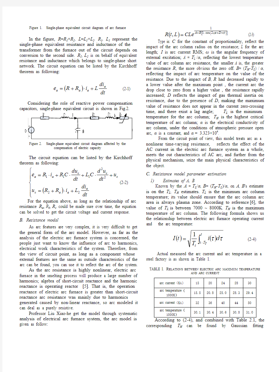
Figure 1. Single-phase equivalent circuit diagram of arc furnace
In the figure, R =R 1+R 2, L =L 1+L 2. R 1, L 1 represent the single-phase equivalent resistance and inductance of the transformer from the furnace out of the circuit depends on conversion to the second side. R 2, L 2 is on behalf of equivalent resistance and inductance which belongs to single-phase short network. The circuit equation can be listed by the Kirchhoff theorem as following:
()dt
di L
i R R e a a a a +?+= (2-1)
Considering the role of reactive power compensation
capacitors, single-phase equivalent circuit is shown in Fig.2.
Figure 2. Single-phase equivalent circuit diagram affected by the
compensation of electric capacity
The circuit equation can be listed by the Kirchhoff theorem as following:
()???
???
?+?+=+?+?+?=dt di L i R R u u dt
u d C L dt du C R i R e a
a a c c c c a a 2222111(2-2) For the equation above, as long as the relationship of arc
resistance R a , R b , R c could be made sure over time, the equation can be solved to get the circuit voltage and current response. B. Resistance modal
As arc features are very complex, it is very difficult to get the general form of the arc model. However, as far as the analysis of the electric arc furnace system is concerned, the people just want to know the influence of arc to harmonics, electrical work characteristics of the system. Therefore, from the view of circuit point, as long as a component whose external features are the same as outside characteristics of the arc can be found, you can use it to reflect the arc of the system.
As the arc resistance is highly nonlinear, electric arc furnace in the smelting process will produce a large number of harmonics; algebra of short-circuit reactance and the harmonic reactance is operating reactor [5]. That is, the operation reactance of electric arc furnace is greater than short-circuit reactance arc resistance was mainly due to harmonics generated caused by non-linear reactance, so arc modeled it can deal as a purely resistive.
Professor Liu Xiao-he get the model through systematic analysis of electrical arc furnace system, the arc model is given as follow:
()()[]
θω++?+=D t B A CLe L t R 2cos 11
, (2-3) Type in: C for the constant of proportionality, reflect the impact of the arc column radius on the resistance; L for the arc length; I is arc current RMS; ω is the angular frequency of external excitation; A = T L /α, reflecting the lowest temperature value of arc column arc resistance, the smaller A is, the greater the resistance R , the more obvious the zero off. B = (T H -T L ) / α, reflecting the impact of arc temperature on the value of the resistance. Due to the impact of B , R had decreased rapidly to a lower value after the maximum point , the current arc the drop close to zero from a higher value , the resistance rapidly increased; D reflects the impact of gas thermal inertia on resistance, due to the presence of D , making the maximum value of resistance does not appear in the current zero-crossing time, and there exist a lag angle; T L is the minimum temperature for the arc column; T H is the highest critical temperature of arc column; α is the electrical conductivity of arc column, under the conditions of atmospheric pressure open arc, α is a constant, and α = 3.323×10⁴.
From the circuit point of view, this model treats arc as a nonlinear time-varying resistance, reflects the effect of the AC current in the electric arc furnace system as a whole, meets the out characteristics of AC arc, and further from the physical mechanism, seize the main physical characteristics of the object.
C. Resistance model parameter estimation
1) Estimates of A, B
Known by the A = T L /α, B = (T H -T L )/α, on A , B 's estimate is on the T L , T H estimates. T L is the minimum arc column temperature; its value should ensure that the arc column arc area is always plasma zone. According to reference [6], the value of T L is between 7000 ~ 8000K. T H is the maximum temperature of arc column. The following formula shows us the relationship between electric arc furnace operating current and the arc temperature:
()()∫?=
t
T t t
T
d i T t I ττ1 (2-4)
Actual measured the arc current and arc temperature in a
steel factory is as shown in Table 1.
TABLE I. R ELATIONS BETWEEN ELECTRIC ARC MAXIMUM TEMPERATURE
AND ARC CURRENT
arc current (KA) 15 20 24 28 30 arc temperature (
1000K) 15.5 20.8 25.0 28.329.4arc current (KA) 32 36 40 44 50 arc temperature (
1000K)
30.1
30.4
30.6
30.8
31.0
corresponding T H can be found by Gaussian fitting
Interpolation. This method can reduce the error to the extent permitted. Fitting results are shown in Fig.3.
.
Figure 3. Gaussian interpolation
2)
Estimates of C
Since L is usually difficult to obtain, so we took C 0= C*L , divided the period T into N deciles, took N = 60. ()
∑=???
??
???????+?+?≈
N
K D N K B A e
r
ctg L N C 1
4cos 11
'0
π?ω (2-5)
L' is the decoupling and simplification of the equivalent inductance. r is the equivalent resistance of the net short and electric arc furnace transformer. According to the above formula, we obtained the value of C 0 is 3.027×10⁻⁴. 3) D estimates Electric arc furnace is used to operate a large arc current, high arc column temperature, more fully ionized. According to the results of several simulation practices, to determine the values of D at -8 ~ -12 degrees would be more appropriate [7]. It is very difficult to study the harmonic of electric arc furnace system, because the arc resistance is a random variable. In this article, the arc resistance added into the whole circuit as a time-varying model, then obtain the U-I characteristic curve through simulation, and finally analyzed harmonic through the FFT algorithm. Time-varying arc resistance curve is shown in Fig.4.
Figure 4. Time-variable curve of arc resistance
III.
SIMULATION AND ANALYSIS OF RESULT
A. Main parameters of the system
The electric arc furnace parameters in this paper: Rated capacity of electric arc furnace transformer is: when Se =12500KVA and U k %=8%,then R T ≈0?,X T ≈7.3984×10⁻⁴
?; Short Net: R 0=0.0011?,X 0=0.0037338?; arc: T L =8000K ,T 1=28000K, C =1.01×10⁻⁴, L =25cm ,cos φ=0.8,r c =0.45cm ,D +θ=-2.4rad, through calculation A =0.241, B =0.3.
The main arc circuit is shown in Fig.5 [8]. Furnace receives the high voltage power line through short network, furnace transformers, reactors, circuit breakers and isolation switches. Generally, reactive power compensation capacitors should be added in the high side. Large-capacity electric arc
furnace are configured fast static var compensator in foreign.
Figure 5. Schematic diagram of electric arc furnace power supply system
B. Simulation and analysis
Based on the data above, we used Matlab7.0 to simulate
the system. Using module called Powergui, which is located in the library of Power System Blocks, analyze simulation waveform FFT. Powergui is a powerful tool that is provided by Power System Blockset. It can be used for harmonic analysis, convenient and fast.
The usage of Powergui is as follows: click the Simulink menu bar in Simpowersystem of module library, locate the Powergui module, add it to the model in the window which need to simulate, pop-up properties by double-click the Parameters dialog box. FFT Analysis tool can be used to simulate system by the Fourier analysis, to get the harmonic content. Results are generally displayed by bar charts and data table. Fig.6 is the AC arc V-I characteristic curve. From the diagram, a highly nonlinear variation between arc voltages and
currents could be found.
Figure 6. Ac arc V-I characteristic curve
Under the arc voltage and current relationships, we made V-I characteristics of arc shown in Fig.7. Simulation time is 0.1s, simulation step is 45. The random of arc voltage and current fluctuations can be seen from this graph.
Figure 7. Arc voltage, current curve
After fast Fourier decomposition, we get all the frequency spectrum of the harmonics as shown in Fig.8 and Fig.9 from the voltage and current waveforms which are showing us a simulation curve of single-phase arc voltage and
arc current.
Figure 8.
Simulated harmonic contents of voltage
Figure 9. Simulated harmonic contents of current
IV. C ONCLUSIONS
In this paper, arc model which is established for harmonic analysis based on detailed analysis of operating characteristics of electric arc furnace. A simulation of electric arc furnace steel plant shows that the model can reproduce the true arc voltage, current and voltage characteristics. So it can be used in the study of electrical characteristics. The harmonic analysis on this modal shows that, in the arc voltage and current: 3 to 7 harmonics occupy a large proportion. This study is conducive to the effective harmonic suppression measures, and it has a practical significance to carry out the research of the impact
that electric arc furnace brings to the electrical network for the future.
R EFERENCES
[1] Jia Jun-xia, Liu Xiao-he. Research on detecting method of harmonic and
undulate for electric arc furnace. Electric Drive Automation, 2003, 25(3):710(in Chinese).
[2] Wang Jing, Shu Hong-chun, Lin Min, etal. Modeling and simulation of
AC arc furnace for dynamic power quality studies [J].Transactions of China Electro technical Society, 2003,18(3):53-58(in Chinese)
[3] H. Mokhtari, M. Hejri. A New Three Phase Time Domain Model for
Electric Arc Furnaces Using MATLAB[J], IEEE/PES Transmission and Distribution Conference and Exhibition,2002, 3(3):25-29.
[4] Sun Yan-hui, Wang Li-ping, Wang Cheng-xi, etal. Measurement and
study of harmonic on AC-EAF [J].Iron and Steel, 2004, 39(3):20-22(in Chinese).
[5] Liu Xiao-he, Cheng Shao-geng, Su Wen-cheng. Analytical Study of Arc
Furnace Electrical System [J]. Trans-actions of China Electro technical Society, 1994, 5 (2): 21-26.
[6] Lü Xiao-dong, LIU Xiao-he. Simulations on the Impact of Electrode
Regulator on the Voltage Fluctuation [J], Proceedings of the CSEE, 2006, 26(7):95-100.
[7] WANG Yan, MAO Zhi-zhong, LI Yan, TIAN Hui-xin, YUAN Ping, An
Electric Arc Model of AC Electric Arc Furnace for Research on Voltage Fluctuation [J].Power System Technology, 2010, 34(1):36-40.
[8] WANG Yu-fei, JIANG Jian-guo, A Novel Chaotic Model of AC
Electric Arc Furnace for Power Quality Study [J].Proceedings of the CSEE, 2008, 28(10):106-110(in Chinese).
[9] Q i Bi-ru, Xiao Xiang-ning. Modeling and simulation of an arc furnace for
voltage fluctuation investigation [J]. Transactions of China Electromechanical Society, 2000, 15(3):31-35(in Chinese).
[10] WANG Yan, MAO Zhi-zhong, LI Yan, TIAN Hui-xin, YUAN Ping, An
Electric Arc Model of AC Electric Arc Furnace for Research on Voltage Fluctuation [J].Power System Technology, 2010, 34(1):36-40.
[11] Liu Xiao-he, Zhang Dao-cheng. Research on discrete-time adaptive control
of electrode regulator system of arc furnace [J]. Journal of System Simulation, 2004, 16(4):634-636(in Chinese).
[12] Mediana A, Gomez-martinez M A, Fuerte-esquivel C R. Application of
bifurcations theory to assess nonlinear oscillations produced by AC electric arc furnaces [J]. IEEE Trans. Power Delivery, 2005, 20(2):801-806.
超声刀刀头的使用和保养注意事项-
超声刀刀头的使用和保养注意事项 来源:医疗维修在线 时间:2014.1.14 超声刀刀头的使用和保养注意事项超声刀放置在离电刀至少1米远处,如果可能,将主机插入两个不同的墙壁电源出口。 在按STANDBY 后开始测试(针对数码超声刀)必须完成整个测试过程,否者测试会再重复测试时刀头必须在空气中,钳口张开。测试可由脚控或手控操作。测试和使用过程不要触摸刀头。 使用时最好把组织钳夹在刀头前2/3的部位进行操作。 使用每隔10~15分钟时,把刀头浸在水中踩脚档并轻轻抖动,把刀头里的组织和血块冲出,以免堵塞。 清洗10mm刀芯时用软布轻擦,切忌用刷子刷洗,以免损伤硅胶环,影响功能(硅胶环影响振奋和能量) 测试时刀头应张开,不要闭合空踩,也不要碰到金属。 持续工作超过10秒对刀头的损伤是最大的,一般7秒钟就会断。尽量放开,再二次工作。 咬住组织后不可以向上挑,提醒医助把组织拉紧,保证一定的张力。 把柄不可以压的太紧,建议拿出,看使用的是哪个面。 工作时,绝对不允许旋转刀头,否则对刀头损伤很大。 虽然可以,但不建议夹太大的组织,尽量游离好。当刀头的咬齿不动时,则套管的牵引丝断了。 可能的原因:压的太紧,张的太开,与消毒方式有关,薰蒸(环氧乙烷),压轴
不要到90° 长时间使用不拿出时,温度高,最易形成结痂块。长期停留会干燥,损伤牵引丝。细铅丝:帮助调整(拉牌子即可,不用拉铅丝)。 不要在血液中使用。 不用超声刀时应及时停关,使用完毕后按STANDBY键,5分钟后关闭主机。刀头用完后宜马上清洗,避免血块凝固,影响清洗效果。 把刀头浸泡在适酶中,可以分解血液和蛋白。 刀头是一次性的,后几次的使用肯定不如新刀好。挽回成本后,出于对病人的考虑就不要再使用了。 v手柄和刀头的消毒方法----薰蒸(环氧乙烷)。
超声刀使用方法
超声刀使用方法 1、超声刀主机应插入与用电源出口,在按STANDBY后开始测试,测试时刀头必 须在空气中,钳口张开,测试可由脚控戒手控操作。必须完成整个测试过程,测刀头应张开不要闭和空踩,也不要碰到金属。否则测试会再重复。 2、持续工作超过10秒钟对刀头的损伤是最大的,一般7秒钟就会断,尽量放开,再二次工作。使用时最好把组织钳夹刀头前2/3的部位进行操作,使用时每隔10-15分钟时,把刀头侵在水中踩脚挡并轻轻抖动,把刀头里的组织和血冲出,以免堵塞。 3、工作时绝对不允许旋刀头,否则严重损伤刀头。咬住组织不可以向挑,提醒 医生把组织拉紧保证一定的张力。 4、使用完毕后按STANDBY键,5分钟后关闭主机。刀头用完后宜马上清洗,清洗10mm刀芯时,用软布轻擦去刀头表面的组织残渣和凝结物,切忌用刷子刷洗,以免损伤硅胶环影响功能,浸入适酶溶液浸泡、清洗、干燥保管。 5、使用超声刀前应熟悉其拆装及操作规程, 手术中长时间不使用超声刀时,可将其调至STANDBY状态。操作过程应注意保护好手柄轴线, 防止被尖锐器械刺破。清洁刀头时不能用力的进行擦、刮, 防止损坏防粘层, 然后用软布擦干戒吹干各部件; 放置时应盘旋放置,保持线圈直径达15~20 cm ,防止导线折断。另外,5mm的超声刀本来就很容易坏,我们都是用10mm的。 常用于超声刀的消毒方法:环氧乙烷戒者低温等离子灭菌较好。 超声刀使用寿命很大程度上取决于使用者和管理者,还是学会保养: 1 安装刀片时不能使用暴力,应用扭力扳手将其卡紧。清洗时应轻拿轻放,避免重压戒掉落地面使刀具变形; 2 手术中:
1)测试和使用过程中不要触摸刀头,不要碰到金属、骨骼。在没有钳夹组织时踩脚踏,刀头要张开,不要闭合空踩,使用时最好把组织钳夹在刀头前的大部分; 2,使用每隔10min~15min时,把刀头浸在水中踩脚档并轻轻抖动,把刀头里的组织和血块冲出,以免堵塞; 3,清洗10min刀芯时用软布轻擦,切忌用刷子刷,以免损伤硅胶环,影响功率; 4) 不要在血液中使用,否则对刀头损伤很大; 5) 持续工作超时10妙对刀头的损伤是最大的,一般7妙就会断开,尽量放开,再二次工作; 6) 咬住组织后不可以向上挑,提醒助手将组织拉紧,保证一定的张力,工作时绝对不允许旋转刀头,否则对刀头损伤很大。组织游离好后再夹持,不要夹持太大块组织; 7) 每次分离组织后,洗手护士要及时用湿纱布抹净刀头上附着的焦痂及组织,并将刀头放入水中震荡清洗,保持清洁才能保证输出功率; 4 术后卸下刀头后将其浸泡于多酶清洗液,可以分解血液和蛋白,5-10min后清洗,刀面的管腔用加压水枪冲净后用氧气吹干。避免用消毒净浸泡,特殊感染除外,,因其会降低超声刀的使用寿命;不要将手柄泡在液体中。 以上这些都可以延长刀具的使用寿命。 5 收藏注意:手柄连线保护非常重要,因为电能不超声震荡的转换是通过手柄来进行传导的。收藏时应保持线圈直径达15~20cm ,防止导线折断。 ultrasound knife
超声刀安装使用方法和注意事项
强生豪韵超声刀安装、使用方法及注意事项安装: 1、连接连线 A、连接电源线; B、连接脚踏,脚踏连线与主机的连接注意“红点对红点”; C、连接手柄,手柄与主机的连接注意“白点对白点”。 2、连接刀头 A、左手垂直握银色手柄,右手持刀头杆身,将刀头下方接口套入手柄,保持银色手柄不动,旋转刀头杆身拧紧; B、闭合刀头钳口,穿过扭力扳手,顺时针旋转,听到2声“咔嗒”声后,取下扭力扳手。 3、开启电源 打开电源开关,进入主机自检程序,3声“嘟嘟嘟”提示音后,屏幕显示“3”和“5”,主机面板左侧“STANDBY”键显示橙色。 4、刀头检测--非常重要!!! A、轻按“STANDBY”键,“READY”灯亮; B、保持刀头钳口张开,踩下脚踏“MIN”或“MAX”档位不松开,(如使用手控功能,需按下刀头上“MIN”或“MAX”键不松开)直至出现正常工作的声音为止。(注意:正常工作时,5档为急促的连续嘀嘀声,3档为缓慢的嘟嘟声)5、刀头拆卸 闭合刀头钳口,穿过扭力扳手,逆时针旋转,松动后旋转刀头杆身直至刀头与手柄分离,取下扭力扳手。
注意事项: 1、手柄注意小心轻放,避免摔碰,清洗时用中性洗涤剂,避免接口进水。 2、刀头检测时,踩脚踏或按键的时间要充分,更换刀头必须重新进行刀头检测; 3、切忌刀头钳口内不夹持组织而关闭进行激发,也不可夹持硬物进行激发,如骨组织、手术器械等。 4、不可夹持过多过厚组织,最好使用刀头钳口的前2/3部分夹持组织操作。 5、ACE系列刀头关闭刀头钳口时必须听到“咔嗒”声后方可激发。 6、钳口压力、组织张力、档位选择、作用时间和刀头状态均会影响使用效果。 7、在重要脏器、神经、血管附近操作时,注意把刀头钳口隔热的垫片一侧靠近脏器、神经、血管进行操作。 8、使用过程中,如钳口内残余组织较多时,可用湿纱布轻擦,也可先用缝针挑出钳口内组织,然后在温水中张开钳口激发,一定注意钳口不可触碰容器。 9、如不使用手控功能,请勿开启主机面板右侧的“HAND ACTIVATION”键。 10、使用中避免拉动连线来拖拽脚踏,以免损坏脚踏连线。 11、不同的刀头要使用不同的手柄和扳手,详见手柄与刀头适配卡片。
超声刀使用方法
1、超声刀主机应插入专用电源出口,在按STANDBY后开始测试,测试时刀头必须在空气中,钳口张开,测试可由脚控或手控操作。必须完成整个测试过程,测刀头应张开不要闭和空踩,也不要碰到金属。否则测试会再重复。 2、持续工作超过10秒钟对刀头的损伤是最大的,一般7秒钟就会断,尽量放开,再二次工作。使用时最好把组织钳夹刀头前2/3的部位进行操作,使用时每隔10-15分钟时,把刀头侵在水中踩脚挡并轻轻抖动,把刀头里的组织和血冲出,以免堵塞。 3、工作时绝对不允许旋刀头,否则严重损伤刀头。咬住组织不可以向挑,提醒医生把组织拉紧保证一定的张力。 4、使用完毕后按STANDBY键,5分钟后关闭主机。刀头用完后宜马上清洗,清洗10mm 刀芯时,用软布轻擦去刀头表面的组织残渣和凝结物,切忌用刷子刷洗,以免损伤硅胶环影响功能,浸入适酶溶液浸泡、清洗、干燥保管。 5、使用超声刀前应熟悉其拆装及操作规程, 手术中长时间不使用超声刀时,可将其调至STANDBY状态。操作过程应注意保护好手柄轴线, 防止被尖锐器械刺破。清洁刀头时不能用力的进行擦、刮, 防止损坏防粘层, 然后用软布擦干或吹干各部件; 放置时应盘旋放置,保持线圈直径达15~20 cm ,防止导线折断。另外,5mm的超声刀本来就很容易坏,我们都是用10mm的。 常用于超声刀的消毒方法:环氧乙烷或者低温等离子灭菌较好。 超声刀使用寿命很大程度上取决于使用者和管理者,还是学会保养: 1 安装刀片时不能使用暴力,应用扭力扳手将其卡紧。清洗时应轻拿轻放,避免重压或掉落地面使刀具变形;
2 手术中: 1)测试和使用过程中不要触摸刀头,不要碰到金属、骨骼。在没有钳夹组织时踩脚踏,刀头要张开,不要闭合空踩,使用时最好把组织钳夹在刀头前的大部分; 2)使用每隔10min~15min时,把刀头浸在水中踩脚档并轻轻抖动,把刀头里的组织和血块冲出,以免堵塞; 3)清洗10min刀芯时用软布轻擦,切忌用刷子刷,以免损伤硅胶环,影响功率; 4) 不要在血液中使用,否则对刀头损伤很大; 5) 持续工作超时10妙对刀头的损伤是最大的,一般7妙就会断开,尽量放开,再二次工作; 6) 咬住组织后不可以向上挑,提醒助手将组织拉紧,保证一定的张力,工作时绝对不允许旋转刀头,否则对刀头损伤很大。组织游离好后再夹持,不要夹持太大块组织; 7) 每次分离组织后,洗手护士要及时用湿纱布抹净刀头上附着的焦痂及组织,并将刀头放入水中震荡清洗,保持清洁才能保证输出功率; 4 术后卸下刀头后将其浸泡于多酶清洗液,可以分解血液和蛋白,5-10min后清洗,刀面的管腔用加压水枪冲净后用氧气吹干。避免用消毒净浸泡(特殊感染除外),因其会降低超声刀的使用寿命;不要将手柄泡在液体中。 以上这些都可以延长刀具的使用寿命。 5 收藏注意:手柄连线保护非常重要,因为电能与超声震荡的转换是通过手柄来进行传导的。收藏时应保持线圈直径达15~20cm ,防止导线折断。 ultrasound knife
超声刀的操作流程
超声刀操作规程 一、装机拆机步骤 1、主机手柄连接,手柄的白点对准主机手柄连接口的白点,接入即。 2、手柄刀头连接 ①左手竖直向上抓持手柄,右手把刀头自上而下投入,拇指与食指抓住杆身顺时针旋转至紧。 ②关闭钳口,竖直插入扭力扳手,顺时针旋转直至听到两声“咔哒”声。 ③关闭钳口,取出扭力扳手,刀头手柄连接完毕。 3、拆机:关闭电源——拆卸主机手柄——拆卸手柄刀头。(竖直向上、扭力扳手、逆时针)二,开机与检测: 1、主机自测:打开电源开关——面板上所有灯同时亮起——听到“嘟嘟嘟”三声——屏幕显示主机型号——屏幕出现3和5——standby键灯亮——自测完成。 2、刀头检测,按下standby——ready键亮起——手持刀头,点亮手控键——张开钳口,长按激发纽(mi n∕max)不松手——听到主机有特别的测试音调,同时屏幕显示漏斗状,下方显示test in progress字样——声调变成激发时的“滴滴滴”声,屏幕重回3和5字样——松开激发钮——刀头检测通过,可以使用。 三、使用及保养注意事项
1、手柄在使用过程中应轻拿轻放,否则如碰撞或跌落使手柄内部陶瓷破裂,导致手柄不能正常工作或报废。 2、在使用过程中护士应提醒医生在10—15分时在盐水中悬空震荡,避免刀头管腔内吸入血液或组织,切记钳口张开。 3、在使用过程中,刀头钳口不能碰到任何骨质组织和金属器具。 4、超声刀安装地点一般要与电刀相隔一米左右。 5、收纳手柄线尽量不要绕小圈,避免连接线内部导丝断裂,影响使用效果。 6、术后擦净手柄表面的血迹和残留物,戴上红色保护帽,避免连接线端口处的镀金面脱落。 7、术后刀头的钳口不可使用硬毛刷用力刷洗,避免钳口部白色垫片脱落,不能起到良好的绝缘作用使整个刀头报废。 8、手柄及刀头均可使用环氧乙烷、等离子消毒。