Optimal PID Design for Control of Active Car Suspension System(IJITCS-V10-N1-2)
I.J. Information Technology and Computer Science, 2018, 1, 16-23
Published Online January 2018 in MECS (https://www.360docs.net/doc/529217745.html,/)
DOI: 10.5815/ijitcs.2018.01.02
Optimal PID Design for Control of Active Car
Suspension System
O. Tolga Altinoz
Ankara University, Department of Electrical and Electronics Engineering, Ankara, 06830, Turkey
E-mail: taltinoz@https://www.360docs.net/doc/529217745.html,.tr
A. Egemen Yilmaz
Ankara University, Department of Electrical and Electronics Engineering, Ankara, 06830, Turkey
E-mail: aeyilmaz@https://www.360docs.net/doc/529217745.html,.tr
Received: 13 October 2017; Accepted: 01 December 2017; Published: 08 January 2018
Abstract—This research is based on the determination of the parameters of the PID and fractional-order PID controllers designed for quarter-car suspension system. Initially, without considering the active suspension structure, the performance of the passive suspension system under different wheel load index is presented by using the transfer function of the system. Then, by adding a wheel-load, the classical PID controller is designed and applied to the current controlled hydraulic actuator as a part of active suspension system. The parameters of this controller are determined by three heuristic optimization algorithms; Particle Swarm Optimization (PSO), Differential Evolution (DE) and Gravitational Search Algorithm (GSA). As the second part of this study after evaluating the performance of classical PID controller, fractional-order PID controller is designed and applied to the problem to improve the performance of the classical PID controller. Similarly, the parameters of this controller are also obtained by using the same optimization algorithms. In the paper, for modeling the road, instead of sinusoidal (road with hill) or random changes, a saw tooth signal is preferred as a relatively harder condition. Implementation results are showed that the performance of the fractional-order PID controller is much better that PID controller and also instead of relatively complex and expensive controller, it is possible to use fractional-order PID controller for the problem.
Index Terms—PID Control, Fractional-order PID control, Particle Swarm Optimization, Differential Evolution, Gravitational Search Algorithm, suspension system, quarter-car.
I.I NTRODUCTION
Suspension systems are installed between car body and wheel to absorb the undesired vibration which occurs due to the road condition. Road handling capability of any transportation vehicle (wheeled vehicles) is the key factor for safety and comfort of the passengers, and it has direct relation with suspension system. The necessity of suspension systems can be summarized as:
i. To absorb the vibration due to the imperfect conditions of the way,
ii. To comfort of the passengers from way conditions, iii. To transfers braking force to the wheel and protect the integrity between wheel and car body.
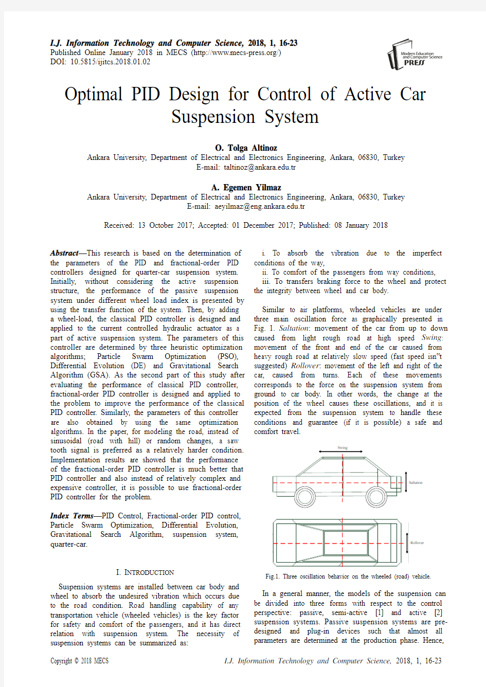
Similar to air platforms, wheeled vehicles are under three main oscillation force as graphically presented in Fig. 1. Saltation: movement of the car from up to down caused from light rough road at high speed Swing: movement of the front and end of the car caused from heavy rough road at relatively slow speed (fast speed isn?t suggested) Rollover: movement of the left and right of the car, caused from turns. Each of these movements corresponds to the force on the suspension system from ground to car body. In other words, the change at the position of the wheel causes these oscillations, and it is expected from the suspension system to handle these conditions and guarantee (if it is possible) a safe and comfort travel.
Rollover
Saltation
Fig.1. Three oscillation behavior on the wheeled (road) vehicle.
In a general manner, the models of the suspension can be divided into three forms with respect to the control perspective: passive, semi-active [1] and active [2] suspension systems. Passive suspension systems are pre-designed and plug-in devices such that almost all parameters are determined at the production phase. Hence,
based on the road conditions, it isn't possible to obtain "robust" response from this device configuration. The advantage of these systems are their relatively low cost, since they generally contain less number of devices (also do not have interconnected devices such as actuator, pneumatics and hydraulics related to suspension system) when compared to other model. Semi active suspension systems have variable damping force and damping coefficients [1], which can be changed by using control algorithms. These systems remain between active and passive systems. An active suspension system, which is the problem environment of this paper, is the enriched version of the passive systems with controllable actuators. These systems can able to supply energy when it is desired [3]. These actuators are controlled by usin current or voltage (based on the structure) change.
Suspension systems are divided into two categories as Depended Systems and Independent Systems. Depended systems indicate a physically connected systems. These systems do not prefer as front suspension systems (at modern automobiles) for years due to their weight and corresponding oscillation. But they are generally preferred as rear suspension systems. The second group is named as independent suspension system where suspensions at each wheel are independent from each other; only anti-roll bar is connected. The well-known independent suspension system is "McPherson" developed in 1947 [4]. As the suspension systems are divided two parts, the corresponding models are similarly divided into three groups: Quarter-car [5], half-car [6] and full-car models [7]. Quarter car model is considered for only one wheel of the vehicle. It is assumed that the designed suspension is for independent suspension system which is the theme of this paper. Half-car model is used for dependent suspension systems, where two suspensions are considered as one system. Full-car model is for overall car model, both front and rear suspension systems are considered.
This paper organized as two main sections following the introduction and literature review section. Section 3 is given for explaining "whats" and "hows" of the paper. The problem (active and passive suspension system), solution (PID and fractional-order PID controllers) and used mathematical tools (optimization algorithms PSO, DE and GSA) are explained in that section. Section 4 is the "results" section. In that part the performance of the controllers and implementation details are presented.
II.L ITERATURE R EVIEW
The control proposals for suspension systems are vary from classical control approaches, robust control, optimal control, to intelligent methods. However, among them one of the oldest and problem oriented control methods is called "Preview Control". The preview control is based on the detection of the road defect, and then based on these data, the control action is formed [3]. This controller can be considered as continuous time optimal control algorithm. Even the performance of this controller is better than classical controller, the necessity for extra sensors at front and rear bumper [6] makes the controller expensive for the proposed performance. Optimal control is applied to both quarter-car [8] and half car models [9]. The survey for optimal control and its design is presented by Sharp and Peng [8]. Krtolica and Hrovat [9], in their paper, they determine optimal closed-loop system eigen-values for a desired damping ration (0.707). Model predictive control (as an adaptive control scheme) is one of the interesting control algorithm for suspension systems. Full-car [7] and semi-active suspension models [1] are evaluated as a part of this controller. Since the model predictive control is a relatively time consuming problem especially for a slow suspension and relatively fast car system. Canale et.al. [1] are proposed a fast model predictive control technique. They also compared their proposed control algorithm with the most basic controllers which are called sky-hook (similar to on-off controller, only two state) and clipped (state-based controller like more stated version of on-off controller) controllers.
Since the controller design idea for suspension systems is based on the robustness of the car body, robust control is frequently applied to the problem. In general, linear matrix inequality (LMI) optimization is applied to H∞ control algorithm for active suspensions [5, 10, 11]. Du and Zhang [12], applied robust state feedback controller to a time delayed suspension system. Like optimal control, the idea is to find desired closed loop poles which give the desired performance. Also Bououden et. al. [13] proposed a robust predictive control method, where quarter-car model is selected and suspension system modeled with Takagi-Sugeno (T-S) fuzzy approach. Fuzzy controller is another controller approach for the problem. Li et. al. [14] designed state and output feedback controllers by converting the problem into optimization problem and solving with an optimization algorithm. In that paper, the system also is onstructed with T-S fuzzy system and uncertainties are also considered. Uncertainties at actuator, sprung and un-sprung masses is a module that taking into account for control design. Li et. al. [15] designed adaptive sliding-mode control (nonlinear control algorithm) and solved the problem by using T-S fuzzy approach. Adaptively and fuzzy is merged on [16] and [17]. Chiou et. al. [16] suggested a Fuzzy PID controller (the outputs of Fuzzy and PID controllers are summed at the controller module) and their parameters are optimized by using PSO. Similarly, at D'Amato and Viassolo paper [17], Fuzzy controller parameters optimized by Genetic Algorithm (GA). GA also applied for active suspension system where parameters of the system are estimated [18, 19]. Optimization is an important tool for determination of the controller parameters as explained previously. It is also possible to optimize the parameters of the components formed the suspension system. In [20], Sun et. al., in [21] Prabakar et. al. and in [22] Yao et. al. used optimization algorithm to find the MR damper parameters. As a different perspective, Prabakar et. al. preferred a multiobjective (non-dominated sorting genetic algorithm NSGA-II) for MR damper parameters. Multiobjective
optimization is applied to find the controller parameters for semi-active [23] and active suspension systems by estimating the controller gain matrix of the state feedback controller [24].
PID controller as a classical control algorithm is also applied to solve active suspension problem and optimized with heuristic algorithms. In [25], Dangor et. al. proposed a cascaded controller where the parameters of the PID controller are optimized with PSO [26, 27], GA [28] and DE [29] (even there are many paper for PID parameter optimization, this paper compares three well-known optimization algorithms). The results of the paper showed that PSO and DE presents almost same performance and GA optimized parameter controller presented the worst performance.
Hence evaluation of the results from this paper, in this research PID controller parameters are optimized PSO and DE. Also to find a change to improve the PID performance, Gravitational Search Algorithm (GSA) [30] is selected as third optimization algorithm. In this paper first the classical PID controller parameters are optimized by using these three optimization algorithm. Then, to improve the performance of the controller, fractional-order PID controller is designed and optimized as the second part of the study.
III. M ATHEMATICAL D ESCRIPTION OF THE P ROBLEM AND
T OOLSET In this section, the problem environment, mathematical description of the problem, control algorithms and the optimization algorithms used for solving the control problem are discussed. A. Problem Definition
In this paper, the controllers are designed to regulate hydraulic actuator for minimizing the difference between reference load pattern and corresponding car body trajectory for safety and passenger comfort. Fig. 2 illustrates the active suspension system.
k 2
k 1y
x
u
Fig.2. Approximated Description of the Active Suspension
System Model.
The parameters at the figure 2 from bottom to top are; …u ? position change at the bottom of the wheel; the model of the road is applied from this point. The wheel is modeled as an unsprung mass …M 2? with a spring …k 2?.
Spring and damper (with coefficients …k 1? and …b ?) are placed between wheel and car body with mass …M 1?. Mathematical model of the system is presented in Eq.s 1 and 2.
Q A
x y k x y b x
M
1)()(11+-+-= (1)
Q A
x u k x y k x y b y
M
1)()()(212----+-= (2)
The necessary power is distributed from hydraulic actuator by altering the valve opening which is proportionally equal to flow (Q ). The flow is adjusted with the current and modeled as first-order system as given Eq. 3.
i k Q c Q f f +-= (3)
The aim of this paper is to design
controller
for
adjusting the
difference between
road change and body position. Therefore, initially the effect of the change at the level of the wheel to the car position is explained from passive suspension model. Then, controller designed for active suspension system. B. Passive Model Evaluation
M 1
M 2
k 1
k 2b
y
x u
Fig.3. Approximated Description of the Passive Suspension System.
Fig.4. Step Response of the Passive Suspension System with Respect to
Different Wheel Load Rating.
Figure 3 illustrates quarter-car passive suspension model, and Eq.s 4 and 5 give the mathematical
description for this model. Then, transfer function is obtained from differential equations.
u k y k y b x k k x b x
M 12211)(++=+++ (4)
x k x b y k y b y
M 222+=++ (5)
Initially, impact of the car body is investigated from step response of the system. For this purpose, by considering the wheel load index, various car body weights are applied to the transfer function and corresponding step response plots are given in Fig. 4. To obtain Fig. 4 only the weight o f car body (…M 1?) is changed and step responses are presented. From figure (and also it is possible to observe from transfer function) as the size of the body increases, the performance indicators for the transient response also decreases, which are numerically presented in Table 1.
Table 1. Transient Response Properties of the Passive Suspension
System with Respect to Different Wheel Load Rating
Even PID controller are designed for active suspension system, a classical root locus design by using only a proportional g ain …K ? is made and results are graphically demonstrated in Fig. 5. The aim of this design is to show and answer the question that “Why a detailed/complex controller algorithm is needed for this problem?”. Fig.5 gives the root locus design of the only proportionally controlled suspension system. Fig. 5a gives the value of the gain for critically stable system, and gain larger than 2.63 makes the system unstable. In contrary, Fig. 5b gives the desired damping ration value (0.707) and corresponding gain value 4.09. In other words, with only proportional gain it isn?t possible to obtain a stable system with a desired closed loop poles as demonstrated in Fig.5c. Hence, in this paper, PID controllers are designed and parameters
are optimized. In the next section, PID controller (both classical and fractional-order) are explained with the optimization algorithms. C. PID and Fractional-order PID Controller
The classical PID controller is presented in Eq. 6. Three parameters are needed to be optimized for the desired performance. In brief, proportional parameter (K P ) decreases the rise time and steady state error. However, for a relatively large steady state error integral term (K I ) is needed to eliminate this error. The disadvantage of the integral term is the increase at the overshoot. But this increase and decreases is always depended on the structure of the plant. Therefore, in some cases the increase at overshoot and settling time is relatively small. In other cases, derivative term is needed to decrease
overshoot and settling time of the transient response. Table 2 gives the summary of these effects.
s K s
K
K s G D I P C ++=)( (6)
The contribution of the PID controller parameters isn?t accepted for fractional-order PID controller (FOPID). However, FOPID controller has 2 more degrees flexible than classical PID controller which increases the flexibility of the controller and it is possible to better adjust the dynamic properties of the systems.
(a)
(b)
(c)
Fig.5. Root Locus Plots for the Passive Suspension System a) critically stable condition, b) desired damping ratio line and c) corresponding
unstable system for a desired response
Gain :2.63
Pole :-0.0438+31.6i Damping :0.00138 Overshoot : 99.6%
Gain :2.63
Pole :-0.041+31.6i Damping :0.0013 Overshoot : 99.6%
Gain :4.09
Pole :-9.54+9.52i Damping :0.708 Overshoot : 4.3%
μ
λμs K s K K s K s K K s G d i p D I
P CF ++=++
= ''')('
'
(7)
For a different va lue of λ and μ, fractional -order PID
controller becomes classical PID controller, where for λ'=1 and μ?=1 correspond to the classical PID controller, for λ?=1 and μ?=0 correspond to the PI controller, for λ?=0 and μ?=1 correspond to the PD controller, and for λ?=0 and μ?=0 correspond to the proportional controller.
Table 2. PID Parameters Effects on Transient Response Properties
IV. O PTIMIZATION
One of the objectives of this paper is to present a comparative study between well-known nature inspired optimization algorithms, which are Particle Swarm Optimization [27], Differential Evolution [29] and Gravitational Search Algorithm [30]. These algorithms are briefly explained at the subsections given below. The detailed information related to the optimization algorithms and their behavior can be read from the references at each sub-section. Even the algorithm is changed at each implementation, the objective (fitness) function is remained the same as mean square of the error which is defined as difference between reference trajectory and the output of the overall system.
()∑=-=
n
i out
ref
y y
n
J 1
21 (8)
where n is the number of data collected from simulation environment, y ref is the reference trajectory (in other words the desired behavior of the suspension system with respect to the normalized reference position) and y out is the output of the overall system.
A. Fundamentals of Particle Swarm Optimization Particle Swarm Optimization (PSO) is proposed by Kennedy and Eberhart in 1995 [26]. The algorithm is inspired from the interconnected behaviors of the animal swarms. The algorithm is based on the motions of the overall population and members of the population (called “particles”). Each particle has three properties and the overall swarm has one. Each particle has position, velocity, and personal best position which is the record of the minimum objective position of each particle. Also swarm has record of the best particle and its objective value. The algorithm begins with the randomly initialization of the particles position and velocity. Then by using the position of each particle objective values are
calculated. By using the objective value vector, the particle which has minimum objective value is recorded. At the same time, personal best positions and their objective value are also saved to a vector. At the last step of the algorithm, the position and velocity of each particle is updated by using the function defined in Eq. 9. In this function, two optimization parameters, positions, personal best position and global best solutions are applied to the function. In other words, each particle goes to a random position between personal best position and global best position.
))
(())(()()1(2211k x gbest rand c k x pbest rand k v k v c -+-+=+ (9)
B. Fundamentals of Differential Evolution
Differential Evolution (DE) algorithm was proposed by Storn and Price in 1995 [29]. Similarly, to evolutionary algorithms (like GA [28]), DE has four operators: initialization, mutation, recombination and selection. The algorithm begins with randomly selected initial vector (x ). Then this initial vector applied to a mutation operator. The mutation operator is a function that takes the initial (x ) vector and form a new vector (v ) with the same size. The following equation (Eq. 10) corresponds one of the possible mutation operator.
())()()()1(321k x k x F k x k v r r r i -+=+ (10)
where three vectors (r 1, r 2 and r 3) are selected randomly and difference of two vectors are multiply by an optimization parameter F . After two vector sets (x and v ) have obtained, they applied to recombination operation. From these two vector sets, only one set of vector is selected (u ) by using the optimization parameter (CR ) and a random value from recombined set, selection from recombined vector is made by comparing the value based on "is it smaller or larger than this optimization parameter (CR )". The last operator is the selection. Among two vector set (x and u ) the vectors which has the smallest objective value is selected as survived to the next iteration.
C. Fundamentals of Gravitational Search Algorithm Gravitational Search Algorithm (GSA) is developed by Rashedi et. al. in 2009 [30]. The algorithm is based on the interaction between masses by taking the “law of gravitation” as the basis of the algorithm, the GSA method was developed. The GSA algorithm is a sequential process of four steps: i) initialization of the population (same for three optimization algorithms). Positions and velocities are assigned randomly at the beginning of the algorithm; ii) objective functions are calculated from the position vector. The calculated objective function values are stored in a vector and then best and worst objective values are find and recorded.; iii) update and physical law calculations are evaluated. The gravitational constant G (t ), velocity V and position X
vector is updated in this step (Eq.s. 11 and 12). Each member assigned to a mass value in this section. The mass of members are the normalized objective values. By using these masses, the forces upon on each mass (member) are calculated. The force is proportion to the acceleration with the mass values. At the end of this step the accelerations are calculated. In other words, any member with the smallest objective value has the largest mass. Therefore, other masses are dragged to this mass. But also there are some larger masses and corresponding movement depends on the objective values of masses. The position and velocities are updated by using the following equations; iv) repeat steps 2 and 3 until the termination condition(s) are met.
)()()1(t a t v rand t v i i i i +=+ (11)
)()()1(t v t x t x i i i +=+ (12)
V. I MPLEMENTATION R ESULTS AND D ISCUSSION In the previous sections, the performance of the passive suspension system is investigated with respect to the different wheel load index. Then to indicate the importance of the controller and necessity for a relatively complex control algorithm, a simple proportional coefficient is applied to unity feedback system and with the aid of root locus, the performance of the system discussed. In the following sections, first classical PID controller is designed for active suspension system. Then to improve the performance of the PID controller, a fractional-order PID (FOPID) controller is applied to the overall system instead of classical PID controller. A. Classical PID Controller
In Eq. 6, the laplace transform of the PID controller is presented. The controller has three parameters that need to determine for a desired performance. In the previous studies [25], it was showed that the conventional PID tuning algorithms are present undesired transient response for many cases when compared with the optimization algorithms. Therefore, in this paper three optimization algorithms are applied to find controller parameters. Fig 6 shows the comparison between one of the solutions and the open-loop (no controller) performance.
In Fig. 2, active suspension system model is presented. The change at the level of the wheel is applied as the input of …u?. In this paper, the saw tooth input is preferred as the change at the road. In previous papers, step change, sinusoidal change and random change are considered as road model. The reference point in the figures indicates omitting the height difference. The car body and the top of the wheel remain at the different heights of the car (for some time interval the distance becomes negative for this reason). However, in the figures these differences are cancelled to present graphics efficiently.
Fig.6. The change at the road and corresponding car body vertical
position change with and without PID controller.
(a)
(b)
Fig.7. a) The trajectory of the suspension system for different optimization algorithms and b) error difference between
optimization algorithms.
Fig. 7a illustrates the trajectory of the wheel system controlled via classical PID controller optimized with PSO, DE and PSO algorithms. The minimum mean square error for DE, PSO and GSA are calculated as 1.33 10-3, 1.52 10-3 and 3.69 10-3 respectively. The best objective value is obtained from PID controller optimized with DE algorithm. Even the DE gives the best result, the performances are almost the same for all optimization algorithms. Fig. 7a gives the trajectory for all optimization algorithms and Fig. 7b gives the error differences with respect to the position change. The performances of PSO and DE are almost the same but GSA presents relatively bigger error.
without control action
PSO optimized PID control
GSA DE PSO
|PSO-GSA| |DE-GSA| |DE-PSO|
The trajectory of the wheel is graphically illustrated on Fig. 7. Even the small overshoot occurs and results is much better for open loop response (in Fig. 6), the small overshoot and undershoot decreases the comfort of the passenger. Therefore, to improve the performance of the controller as the next step, FOPID controller parameters are optimized by using the same algorithms.
B. Fractional-order PID Controller
Fractional-order PID is a non-integer-order of the conventional PID controller. Like PID controller, there are PID parameters are needed to be tuned which are K P, K I and K D. Beside them, non-integer orders of the s-parameter are needed to be tuned. Therefore, there are five parameters (additional parameters are λand μ) are optimized. Fig. 8 gives the performance of the FOPID controller with optimized parameters. The minimum errors are obtained for PSO, DE, and GSA are 5.61x10⁻³, 1.15x10⁻³, and 1.04x10⁻³. From the figure the best performance is obtained for PSO algorithm with a very small overshoot. The performance of the DE almost remains the same for classical and fractional order PID implementations. However, GSA presents a much better performance and error reduced from 3.69x10⁻³to 1.04x10⁻³. From the results, the best performance is obtained from PSO algorithm.
Fig.8. The change at the road and corresponding car body vertical position change with and without PID controller.
VI.C ONCLUSION
In this study, active suspension system problem is solved with optimal PID controllers. As the first step of the study, the passive suspension system is investigated and showed with the aid of classical control design method that only a …complete? control algorithm can able to handle to problems of the comfort of passengers and the road handling. Then, classical PID controller is applied to the problem. The parameters of PID controller are obtained by three optimization algorithms; PSO, DE and GSA. From previous studies it is expected that PSO and DE presents almost same performance. These findings are also verified in this study. But to improve the impact one more optimization algorithm GSA is applied and also almost same performance is reach for all optimization algorithms. Even the PID performances is acceptable, it is possible to improve the obtained performance by slightly change the controller structure. For this purpose, fractional-order PID algorithm is designed. Similarly, parameters are optimized by using optimization algorithm. The results are more promising but differences between optimization algorithms become clearer. The best performance is obtained from PSO algorithm. For all implementation GSA presents the worst performance. The best results from FOPID controller is a very small overshoot and bigger undershoot at the hill fall moment. The results suggest that instead of using more complex and expansive control algorithms, it is possible to use low-cost FOPID algorithm with a proper selection of control parameters without need of any additional hardware.
R EFERENCES
[1]M. Canale, M. Milanese, and C. Novara, “Semi-active
suspension control using "fast" model-predictive techniques,”Ieee Transactions on Control Systems Technology, vol. 14, pp. 1034-1046, Nov 2006.
[2]J. T. Cao, P. Li, and H. H. Liu, “An Interval Fuzzy
Controller for Vehicle Active Suspension Systems,”Ieee Transactions on Intelligent Transportation Systems, vol.
11, pp. 885-895, Dec 2010.
[3] A. Hac, “Optimal Linear Preview Control of Active
Vehicle Suspension,”Proceedings of the 29th Ieee Conference on Decision and Control, Vols 1-6, pp. 2779-
2784, 1990.
[4]S. Frik and M. Hiller, “Kinematics and Dynamics of a
Mcpherson Front Wheel Suspension with Elastic Rear Transverse Pivot Bearing,”Zeitschrift Fur Angewandte Mathematik Und Mechanik, vol. 69, pp. T398-T399, 1989.
[5]H. M. Soliman, A. Benzaouia, and H. Yousef, “Saturated
robust control with regional pole placement and application to car active suspension,”Journal of Vibration and Control, vol. 22, pp. 258-269, Jan 2016.
[6]J. Marzbanrad, G. Ahmadi, H. Zohoor, and Y. Hojjat,
“Stochastic optimal preview control of a vehicle suspension,”Journal of Sound and Vibration, vol. 275, pp.
973-990, Aug 23 2004.
[7]Y. L. Hu, M. Z. Q. Chen, and Z. S. Hou, “Multiplexed
model predictive control for active vehicle suspensions,”
International Journal of Control, vol. 88, pp. 347-363, Feb 1 2015.
[8]R. S. Sharp and H. E. Peng, “Vehicle dynamics
applications of optimal control theory,”Vehicle System Dynamics, vol. 49, pp. 1073-1111, 2011.
[9]R. Krtolica and D. Hrovat, “Optimal Active Suspension
Control Based on a Half-Car Model - an Analytical
GSA
DE
PSO
GSA
DE
PSO
Solution,”Ieee Transactions on Automatic Control, vol.
37, pp. 528-532, Apr 1992.
[10]H. Chen and K. H. Guo, “Constrained H(infinity) control
of active suspensions: An LMI approach,”Ieee Transactions on Control Systems Technology, vol. 13, pp.
412-421, May 2005.
[11]W. C. Sun, H. J. Gao, and O. Kaynak, “Finite Frequency
H-infinity Control for Vehicle Active Suspension Systems,”Ieee Transactions on Control Systems Technology, vol. 19, pp. 416-422, Mar 2011.
[12]H. P. Du and N. Zhang, “H(infinity) control of active
vehicle suspensions with actuator time delay,”Journal of Sound and Vibration, vol. 301, pp. 236-252, Mar 20 2007.
[13]S. Bououden, M. Chadli, and H. R. Karimi, “A Robust
Predictive Control Design for Nonlinear Active Suspension Systems,”Asian Journal of Control, vol. 18, pp. 122-132, Jan 2016.
[14]H. Y. Li, X. J. Jing, H. K. Lam, and P. Shi, “Fuzzy
Sampled-Data Control for Uncertain Vehicle Suspension Systems,”Ieee Transactions on Cybernetics, vol. 44, pp.
1111-1126, Jul 2014.
[15]H. Y. Li, J. Y. Yu, C. Hilton, and H. H. Liu, “Adaptive
Sliding-Mode Control for Nonlinear Active Suspension Vehicle Systems Using T-S Fuzzy Approach,”Ieee Transactions on Industrial Electronics, vol. 60, pp. 3328-
3338, Aug 2013.
[16]J. S. Chiou, S. H. Tsai, and M. T. Liu, “A PSO-based
adaptive fuzzy PID-controllers,”Simulation Modelling Practice and Theory, vol. 26, pp. 49-59, Aug 2012. [17] F. J. D'Amato and D. E. Viassolo, “Fuzzy control for
active suspensions,”Mechatronics, vol. 10, pp. 897-920, Dec 2000.
[18] C. Z. Song, Y. Q. Zhao, and L. Wang, “Design of active
suspension based on genetic algorithm,”Iciea 2008: 3rd Ieee Conference on Industrial Electronics and Applications, Proceedings, Vols 1-3, pp. 162-167, 2008.
[19] A. E. Baumal, J. J. McPhee, and P. H. Calamai,
“Application of genetic algorithms to the design optimization of an active vehicle suspension system,”
Computer Methods in Applied Mechanics and Engineering, vol. 163, pp. 87-94, Sep 21 1998.
[20]S. S. Sun, H. X. Deng, H. P. Du, W. H. Li, J. Yang, G. P.
Liu, et al., “A Compact Variable Stiffness and Damping Shock Absorber for Vehicle Suspension,”Ieee-Asme Transactions on Mechatronics, vol. 20, pp. 2621-2629, Oct 2015.
[21]R. S. Prabakar, C. Sujatha, and S. Narayanan, “Response
of a half-car model with optimal magnetorheological damper parameters,”Journal of Vibration and Control, vol. 22, pp. 784-798, Feb 2016.
[22]G. Z. Yao, F. F. Yap, G. Chen, W. H. Li, and S. H. Yeo,
“MR damper and its application for semi-active control of vehicle suspension system,”Mechatronics, vol. 12, pp.
963-973, Sep 2002.
[23]J. H. Crews, M. G. Mattson, and G. D. Buckner, “Multi-
objective control optimization for semi-active vehicle suspensions,”Journal of Sound and Vibration, vol. 330, pp. 5502-5516, Nov 7 2011.
[24]H. J. Gao, J. Lam, and C. H. Wang, “Multi-objective
control of vehicle active suspension systems via load-
dependent controllers,”Journal of Sound and Vibration, vol. 290, pp. 654-675, Mar 7 2006.
[25]M. Dangor, O. A. Dahunsi, J. O. Pedro, and M. M. Ali,
“Evolutionary algorithm-based PID controller tuning for nonlinear quarter-car electrohydraulic vehicle suspensions,”Nonlinear Dynamics, vol. 78, pp. 2795-2810, Dec 2014. [26]J. Kennedy and R. Eberhart, “Particle swarm
optimization,”1995 Ieee International Conference on Neural Networks Proceedings, Vols 1-6, pp. 1942-1948, 1995.
[27]R. C. Eberhart and Y. H. Shi, “Particle swarm
optimization: Developments, applications and resources,”
Proceedings of the 2001 Congress on Evolutionary Computation, Vols 1 and 2, pp. 81-86, 2001.
[28]K. F. Man, K. S. Tang, and S. Kwong, “Genetic
algorithms: Concepts and applications,”Ieee Transactions on Industrial Electronics, vol. 43, pp. 519-534, Oct 1996.
[29]R. Storn and K. Price, “Differential evolution - A simple
and efficient heuristic for global optimization over continuous spaces,”Journal of Global Optimization, vol.
11, pp. 341-359, Dec 1997.
[30] E. Rashedi, H. Nezamabadi-Pour, and S. Saryazdi, “GSA:
A Gravitational Search Algorithm,”Information Sciences,
vol. 179, pp. 2232-2248, Jun 13 2009.
Authors’ Profiles
O. Tolga Altinoz received the B.E.
degree in Electrical and Electronics
Engineering from the Baskent University,
Ankara, Turkey, in 2003, and the MSc
degree in Electrical and Electronics
Engineering from Hacettepe University,
Ankara, Turkey in 2010. He is currently
pursuing the Ph.D. degree with the
Department of Electrical and Electronics Engineering, Ankara University, Ankara, Turkey. His current research interests include evolutionary computation, optimization, control systems, power electronics, and biomedical systems.
A. Egemen Yilmaz received his
B.Sc.
degree in Electrical-Electronics
Engineering from the Middle East
Technical University in 1997. He
received his M.Sc. and Ph.D. degrees in
Electrical-Electronics Engineering from
the same university in 2000 and 2007,
respectively. He is currently with the
Dept. of Electronics Engineering in Ankara University, where he is an Associate Professor. His research interests include computational electromagnetics, nature-inspired optimization algorithms, knowledge-based systems; more generally software development processes and methodologies.
How to cite this paper: O. Tolga Altinoz, A. Egemen Yilmaz, "Optimal PID Design for Control of Active Car Suspension System", International Journal of Information Technology and Computer Science(IJITCS), Vol.10, No.1, pp.16-23, 2018. DOI:
10.5815/ijitcs.2018.01.02