TSOP85236中文资料
IR Receiver Modules for Remote Control Systems
New TSOP852.., TSOP854..
Vishay Semiconductors
FEATURES
?Very low supply current
?Photo detectors and preamplifier in one package
?Internal filter for PCM frequency ?Supply voltage: 2.5 V to 5.5 V
?Improved immunity against ambient light ?Capable of side or top view
?Two lenses for high sensitivity and wide receiving angle ?Component in accordance to RoH S 2002/95/EC and WEEE 2002/96/EC
?Insensitive to supply voltage ripple and noise
DESCRIPTION
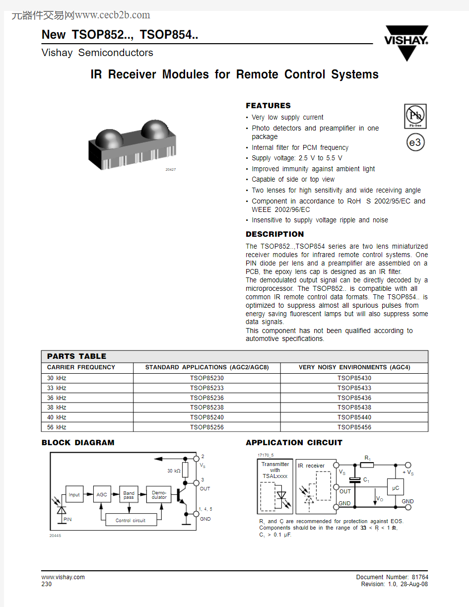
The TSOP852..,TSOP854 series are two lens miniaturized receiver modules for infrared remote control systems. One PIN diode per lens and a preamplifier are assembled on a PCB, the epoxy lens cap is designed as an IR filter.
The demodulated output signal can be directly decoded by a microprocessor. The TSOP852.. is compatible with all common IR remote control data formats. The TSOP854.. is optimized to suppress almost all spurious pulses from energy saving fluorescent lamps but will also suppress some data signals.
This component has not been qualified according to automotive specifications.
BLOCK DIAGRAM
APPLICATION CIRCUIT
20427
PARTS TABLE
CARRIER FREQUENCY STANDARD APPLICATIONS (AGC2/AGC8)
VERY NOISY ENVIRONMENTS (AGC4)
30 kHz TSOP85230TSOP8543033 kHz TSOP85233TSOP8543336 kHz TSOP85236TSOP8543638 kHz TSOP85238TSOP8543840 kHz TSOP85240TSOP8544056 kHz
TSOP85256
TSOP85456
New TSOP852.., TSOP854..
IR Receiver Modules for Remote Control Systems
Vishay Semiconductors
Note
(1)Stresses beyond those listed under “Absolute Maximum Ratings” may cause permanent damage to the device. This is a stress rating only and functional operation of the device at these or any other conditions beyond those indicated in the operational sections of this specification is not implied. Exposure to absolute maximum rating condtions for extended periods may affect the device reliability.
Note (1)T amb = 25°C, unless otherwise specified
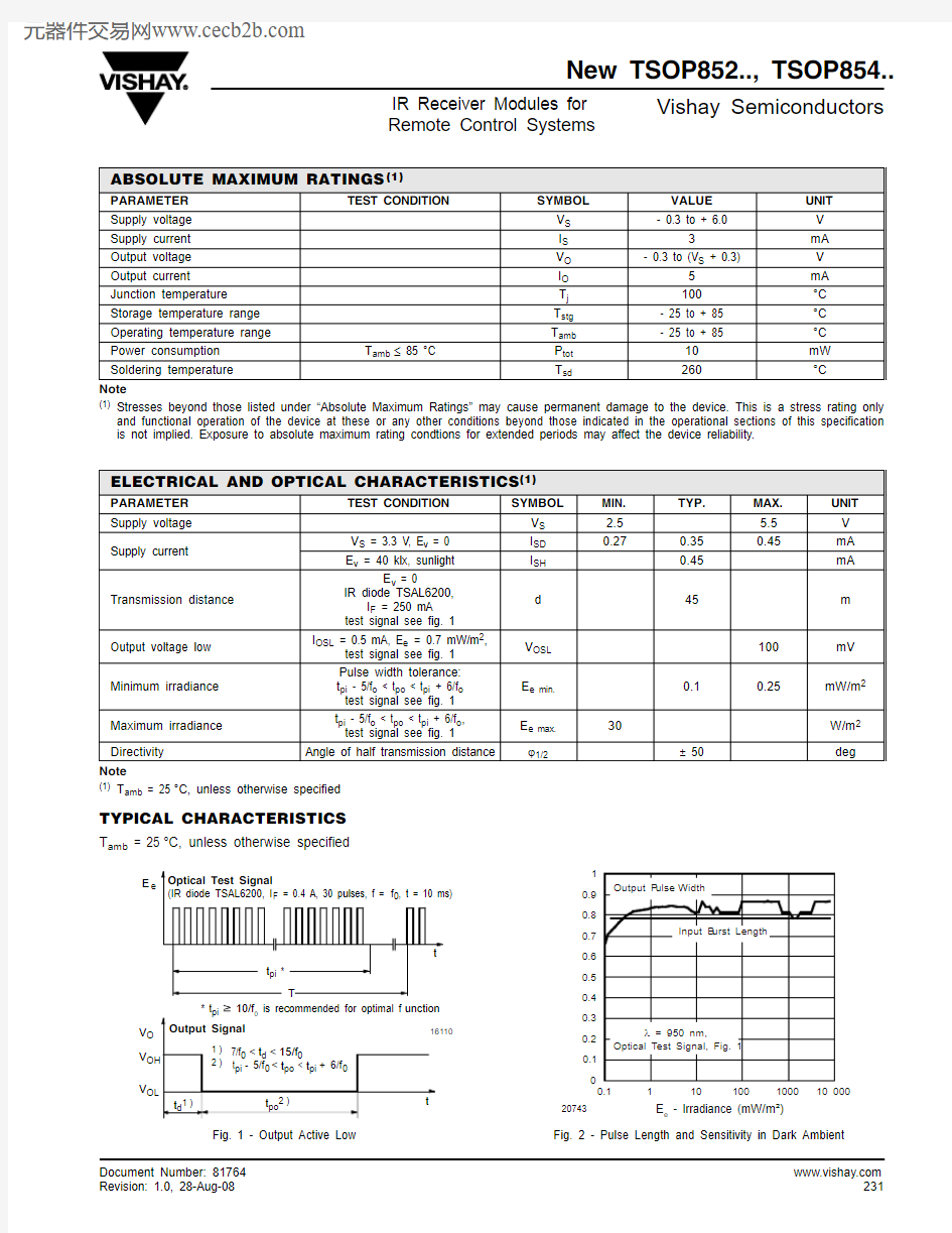
TYPICAL CHARACTERISTICS
T amb = 25°C, unless otherwise specified
Fig. 1 - Output Active Low
Fig. 2 - Pulse Length and Sensitivity in Dark Ambient
ABSOLUTE MAXIMUM RATINGS (1)
PARAMETER TEST CONDITION
SYMBOL
VALUE UNIT Supply voltage V S - 0.3 to + 6.0
V Supply current I S 3
mA Output voltage V O - 0.3 to (V S + 0.3)
V Output current I O 5mA Junction temperature T j 100°C Storage temperature range T stg - 25 to + 85°C Operating temperature range T amb - 25 to + 85
°C Power consumption T amb ≤ 85 °C P tot 10mW Soldering temperature
T sd
260
°C
ELECTRICAL AND OPTICAL CHARACTERISTICS (1)
PARAMETER TEST CONDITION
SYMBOL
MIN.TYP.
MAX.UNIT Supply voltage V S 2.5 5.5V Supply current
V S = 3.3 V, E v = 0I SD 0.27
0.350.45
mA E v = 40 klx, sunlight I SH 0.45mA Transmission distance
E v = 0
IR diode TSAL6200,
I F = 250 mA test signal see fig. 1d
45m
Output voltage low I OSL = 0.5 mA, E e = 0.7 mW/m 2,
test signal see fig. 1
V OSL 100mV Minimum irradiance Pulse width tolerance:t pi - 5/f o < t po < t pi + 6/f o test signal see fig. 1E e min.0.1
0.25
mW/m 2Maximum irradiance t pi - 5/f o < t po < t pi + 6/f o ,test signal see fig. 1E e max.30
W/m 2Directivity
Angle of half transmission distance
?1/2
± 50deg
E e
V O V V
New TSOP852.., TSOP854..
Vishay Semiconductors
IR Receiver Modules for Remote Control Systems
Fig. 3 - Output Function
Fig. 4 - Output Pulse Diagram
Fig. 5 - Frequency Dependance of Responsivity Fig. 6 - Sensitivity in Bright Ambient
Fig. 7 - Sensitivity vs. Supply Voltage Disturbances
Fig. 8 - Sensitivity vs. Electric Field Disturbances
E e
V O V V OL
0.00.20.40.60.81.01.20.7
0.9 1.1 1.3
f/f 0 - Relati v e Fre qu ency
16925
E /E - R e l. R e s p o n s i v i t y e m i n
.e
New TSOP852.., TSOP854..
IR Receiver Modules for Remote Control Systems
Vishay Semiconductors
Fig. 9 - Max. Envelope Duty Cycle vs. Burst Length
Fig. 10 - Sensitivity vs. Ambient Temperature Fig. 11 - Relative Spectral Sensitivity vs. Wavelength
Fig. 12 - Directivity
S ()r
New TSOP852.., TSOP854..
Vishay Semiconductors IR Receiver Modules for
Remote Control Systems SUITABLE DATA FORMAT
The TSOP852.., TSOP854 series are designed to suppress
spurious output pulses due to noise or disturbance signals.
Data and disturbance signals can be distinguished by the
devices according to carrier frequency, burst length and
envelope duty cycle. The data signal should be close to the
band-pass center frequency (e.g. 38 kH z) and fulfill the
conditions in the table below.
When a data signal is applied to the TSOP852.., TSOP854
in the presence of a disturbance signal, the sensitivity of the
receiver is reduced to insure that no spurious pulses are
present at the output. Some examples of disturbance signals
which are suppressed are:
?DC light (e.g. from tungsten bulb or sunlight)
?Continuous signals at any frequency
?Strongly or weakly modulated noise from fluorescent lamps with electronic ballasts (see figure 13 or figure 14)Fig. 13 - IR Signal from Fluorescent Lamp
with Low Modulation
Fig. 14 - IR Signal from Fluorescent Lamp
with High Modulation
Note
For data formats with short bursts please see the data sheet for TSOP853..
0101520
Time (ms)
16920
I
R
S
i
g
n
a
l
5
0101520
Time (ms)
16921
I
R
S
i
g
n
a
l
10
TSOP852..TSOP854..
Minimum burst length10 cycles/burst10 cycles/burst
After each burst of length
a minimum gap time is required of 10 to 70 cycles
≥ 10 cycles
10 to 35 cycles
≥ 10 cycles
For bursts greater than
a minimum gap time in the data stream is needed of
70 cycles
> 4 x burst length
35 cycles
> 10 x burst length
Maximum number of continuous short bursts/second18001500 Compatible to NEC code yes yes Compatible to RC5/RC6 code yes yes Compatible to Sony code yes no Compatible to Thomson 56 kHz code yes yes Compatible to Mitsubishi code (38 kHz, preburst 8 ms, 16 bit)yes no Compatible to Sharp code yes yes
Suppression of interference from fluorescent lamps Most common disturbance
signals are suppressed
Even extreme disturbance
signals are suppressed
New TSOP852.., TSOP854..
IR Receiver Modules for
Vishay Semiconductors
Remote Control Systems
PACKAGE Dimensions in millimeters
New TSOP852.., TSOP854..
Vishay Semiconductors IR Receiver Modules for
Remote Control Systems TAPING VERSION TSOP..TR Dimensions in millimeters
New TSOP852.., TSOP854..
IR Receiver Modules for
Vishay Semiconductors
Remote Control Systems
TAPING VERSION TSOP..TT Dimensions in millimeters
New TSOP852.., TSOP854..
Vishay Semiconductors IR Receiver Modules for
Remote Control Systems
OZONE DEPLETING SUBSTANCES POLICY STATEMENT
It is the policy of Vishay Semiconductor GmbH to
1.Meet all present and future national and international statutory requirements.
2.Regularly and continuously improve the performance of our products, processes, distribution and operating systems with
respect to their impact on the health and safety of our employees and the public, as well as their impact on the environment. It is particular concern to control or eliminate releases of those substances into the atmosphere which are known as ozone depleting substances (ODSs).
The Montreal Protocol (1987) and its London Amendments (1990) intend to severely restrict the use of ODSs and forbid their use within the next ten years. Various national and international initiatives are pressing for an earlier ban on these substances. Vishay Semiconductor GmbH has been able to use its policy of continuous improvements to eliminate the use of ODSs listed in the following documents.
1.Annex A, B and list of transitional substances of the Montreal Protocol and the London Amendments respectively.
2.Class I and II ozone depleting substances in the Clean Air Act Amendments of 1990 by the Environmental Protection Agency
(EPA) in the USA.
3.Council Decision 88/540/EEC and 91/690/EEC Annex A, B and C (transitional substances) respectively.
Vishay Semiconductor GmbH can certify that our semiconductors are not manufactured with ozone depleting substances and do not contain such substances.
We reserve the right to make changes to improve technical design
and may do so without further notice.
Parameters can vary in different applications. All operating parameters must be validated for each customer application by the customer. Should the buyer use Vishay Semiconductors products for any unintended or unauthorized application, the buyer shall indemnify Vishay Semiconductors against all claims, costs, damages, and expenses, arising out of, directly or indirectly, any claim of personal damage, injury or death associated with such unintended or unauthorized use.
Vishay Semiconductor GmbH, P.O.B. 3535, D-74025 Heilbronn, Germany
Disclaimer Legal Disclaimer Notice
Vishay
All product specifications and data are subject to change without notice.
Vishay Intertechnology, Inc., its affiliates, agents, and employees, and all persons acting on its or their behalf (collectively, “Vishay”), disclaim any and all liability for any errors, inaccuracies or incompleteness contained herein or in any other disclosure relating to any product.
Vishay disclaims any and all liability arising out of the use or application of any product described herein or of any information provided herein to the maximum extent permitted by law. The product specifications do not expand or otherwise modify Vishay’s terms and conditions of purchase, including but not limited to the warranty expressed therein, which apply to these products.
No license, express or implied, by estoppel or otherwise, to any intellectual property rights is granted by this document or by any conduct of Vishay.
The products shown herein are not designed for use in medical, life-saving, or life-sustaining applications unless otherwise expressly indicated. Customers using or selling Vishay products not expressly indicated for use in such applications do so entirely at their own risk and agree to fully indemnify Vishay for any damages arising or resulting from such use or sale. Please contact authorized Vishay personnel to obtain written terms and conditions regarding products designed for such applications.
Product names and markings noted herein may be trademarks of their respective owners.
元器件交易网https://www.360docs.net/doc/5c16465965.html,