93-21UYC中文资料
Technical Data Sheet
High Performance SMD LED with Reflector
93-21UYC/S530-XX/TR8 Features Array?Compatible with automatic placement equipment.
?Compatible with infrared and vapor phase reflow
solder process.
?Eia std. package.
?IC compatible.
?Pb- free
Applications
?Automotive: backlighting in dashboard and switch.
?Telecommunication: indicator and backlighting in
telephone and fax.
?Indicator and backlight for audio and video equipment
?Indicator and backlight for battery driven equipment.
?Flat backlight for LCD, switch and symbol.
?Light pipe application.
?General use.
Device Selection Guide
Chip
Lens Color
Color
Material Emitted
AlGaInP Super Yellow Water Clear
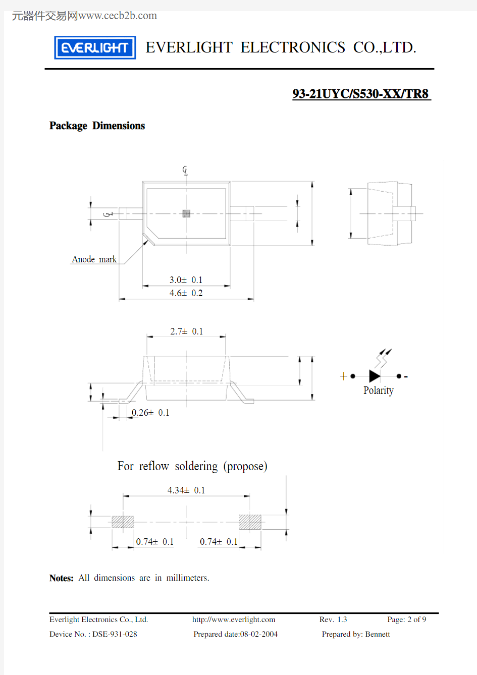
93-21UYC/S530-XX/TR8 Package Dimensions
Notes: All dimensions are in millimeters.
93-21UYC/S530-XX/TR8
Absolute Maximum Ratings (Ta=25℃)
Parameter Symbol Rating Unit Reverse Voltage V R 5 V Forward Current I F 25 mA
Operating Temperature Topr -40 ~ +85 ℃ Storage Temperature Tstg -40~ +100 ℃ Soldering Temperature Tsol 260 (for 5 second)
℃ Power Dissipation
Pd
60
mW
Peak Forward Current(Duty 1/10 @ 1KH Z )
I FP 60 mA
Electro-Optical Characteristics (Ta=25℃)
Parameter
Symbol
*Chip Rank
Min. Typ. Max. Unit
Condition
A2 17
43
-----
A3 40 63 -----
A4 55 85 ----- A5 65 93 ----- Luminous intensity
Iv
A6 86 126 -----
mcd
If=20mA
Viewing Angle 2θ1/2 ----- ----- 130 ----- deg If=20mA Peak Wavelength
λp ----- ----- 591 ----- nm If=20mA Dominant Wavelength
λd ----- ----- 589 ----- nm If=20mA Spectrum Radiation
Bandwidth △λ ----- ----- 15 -----
nm If=20mA Forward Voltage V F
-----
----- 2.0 2.4
V
If=20mA Reverse Current
I R ----- ----- ----- 10 μA
Vr=5V
*93-21UYC/S530-XX/TR8
Chip Rank
93-21UYC/S530-XX/TR8
93-21UYC/S530-XX/TR8
Note: The tolerances unless mentioned is ±0.1mm ,Unit = mm
93-21UYC/S530-XX/TR8
93-21UYC/S530-XX/TR8
Reliability Test Items And Conditions
The reliability of products shall be satisfied with items listed below. Confidence level :90% LTPD :10%
No. Items Test Condition Test Hours/Cycles Sample
Size
Ac/Rc
1 Solder Heat
Temp. : 260℃±5℃
Min. 5sec. 6 Min. 22 PCS.0/1 2 Temperature Cycle H : +100℃ 15min
∫ 5 min
L : -40℃ 15min 300 Cycles 22 PCS.0/1 3 Thermal Shock H : +100℃ 5min
∫ 10 sec
L : -10℃ 5min
300 Cycles 22 PCS.0/1 4
High Temperature
Storage
Temp. : 100℃ 1000 Hrs. 22 PCS.0/1 5
Low Temperature
Storage Temp. : -40℃ 1000 Hrs. 22 PCS.
0/1
6 DC Operating Life I F = 20 mA 1000 Hrs. 22PCS. 0/1
7 High Temperature /
High Humidity
85℃/ 85%RH
1000 Hrs. 22 PCS.
0/1
93-21UYC/S530-XX/TR8 Precautions For Use
1. Over-current-proof
Customer must apply resistors for protection , otherwise slight voltage shift will cause big
current change ( Burn out will happen ).
2. Storage
2.1 Do not open moisture proof bag before the products are ready to use.
2.2 Before opening the package, the LEDs should be kept at 30℃or less and 90%RH or less.
2.3 The LEDs should be used within a year.
2.4 After opening the package, the LEDs should be kept at 30℃or less and 70%RH or less.
2.5 The LEDs should be used within 168 hours (7 days) after opening the package.
2.6 If the moisture absorbent material (silica gel) has faded away or the LEDs have exceeded the
storage time, baking treatment should be performed using the following conditions.
Baking treatment : 60±5℃for 24 hours.
3. Soldering Condition
3.1 Pb-free solder temperature profile
3.2 Reflow soldering should not be done more than two times.
3.3 When soldering, do not put stress on the LEDs during heating.
3.4 After soldering, do not warp the circuit board.
started at the time of the hand solder.
93-21UYC/S530-XX/TR8 4.Soldering Iron
Each terminal is to go to the tip of soldering iron temperature less than 280℃for 3 seconds within once in less than the soldering iron capacity 25W. Leave two seconds and more intervals, and do soldering of each terminal. Be careful because the damage of the product is often started at the time of the hand solder.
5.Repairing
Repair should not be done after the LEDs have been soldered. When repairing is unavoidable, a double-head soldering iron should be used (as below figure). It should be confirmed