SPS-7120BG中文资料
Optoway SPS-7120G
***********************************************************************************************************************************************************************
***********************************************************************************************************************************************************************
OPTOWAY TECHNOLOGY INC. No .38, Kuang Fu S. Road, Hu Kou, Hsin Chu Industrial Park, Hsin Chu, Taiwan 303
Tel: 886-3-5979798 Fax: 886-3-5979737
E-mail: sales@https://www.360docs.net/doc/5218387262.html, http: // https://www.360docs.net/doc/5218387262.html, 12/1/2005 V2.0
1
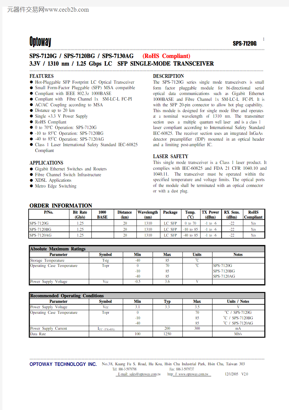
SPS-7120G / SPS-7120BG / SPS-7130AG (RoHS Compliant)
3.3V / 1310 nm / 1.25 Gbps LC SFP SINGLE-MODE TRANSCEIVER
**********************************************************************************************************************************************************************
FEATURES
l Hot-Pluggable SFP Footprint LC Optical Transceiver l Small Form-Factor Pluggable (SFP) MSA compatible l Compliant with IEEE 802.3z 1000BASE
l Compliant with Fibre Channel 1x SM-LC-L FC-PI l AC/AC Coupling according to MSA l Distance up to 20 km
l Single +3.3 V Power Supply l RoHS Compliant
l 0 to 70o C Operation: SPS-7120G l -10 to 85o C Operation: SPS-7120BG l -40 to 85o C Operation: SPS-7120AG
l Class 1 Laser International Safety Standard IEC-60825 Compliant
APPLICATIONS
l Gigabit Ethernet Switches and Routers l Fibre Channel Switch Infrastructure l XDSL Applications l Metro Edge Switching
DESCRIPTION
The SPS-7120G series single mode transceivers is small form factor pluggable module for bi-directional serial optical data communications such as Gigabit Ethernet 1000BASE and Fibre Channel 1x SM-LC-L FC-PI. It is with the SFP 20-pin connector to allow hot plug capability. This module is designed for single mode fiber and operates at a nominal wavelength of 1310 nm. The transmitter section uses a multiple quantum well laser and is a class 1 laser compliant according to International Safety Standard IEC-60825. The receiver section uses an integrated InGaAs detector preamplifier (IDP) mounted in an optical header and a limiting post-amplifier IC.
LASER SAFETY
This single mode transceiver is a Class 1 laser product. It complies with IEC-60825 and FDA 21 CFR 1040.10 and 1040.11. The transceiver must be operated within the specified temperature and voltage limits. The optical ports of the module shall be terminated with an optical connector or with a dust plug.
ORDER INFORMATION
P/No.
Bit Rate (Gb/s) 1000 BASE Distance (km) Wavelength (nm) Package Temp. (o
C) TX Power (dBm) RX Sens. (dBm) RoHS
Compliant SPS-7120G 1.25 20 1310 LC SFP 0 to 70 -1 to -6 -22 Yes SPS-7120BG 1.25 20 1310 LC SFP -10 to 85 -1 to -6 -22 Yes SPS-7120AG
1.25
20 1310 LC SFP -40 to 85 -1 to -6 -22 Yes
Absolute Maximum Ratings
Parameter
Symbol Min Max Units Notes
Storage Temperature
Tstg -40 85 o C
Operating Case Temperature
Topr
0 -10 -40 70 85 85 o C
SPS-7120G SPS-7120BG SPS-7120AG Power Supply Voltage Vcc -0.5
3.6
V
Recommended Operating Conditions
Parameter
Symbol Min Typ Max Units / Notes
Power Supply Voltage
Vcc 3.1 3.3 3.5 V Operating Case Temperature
Topr
0 -10 -40
70 85 85 o
C / SPS-7120G o
C / SPS-7120BG o
C / SPS-7120AG
Power Supply Current I CC (TX+RX)
200 300 mA Data Rate 100
1250
Mb/s
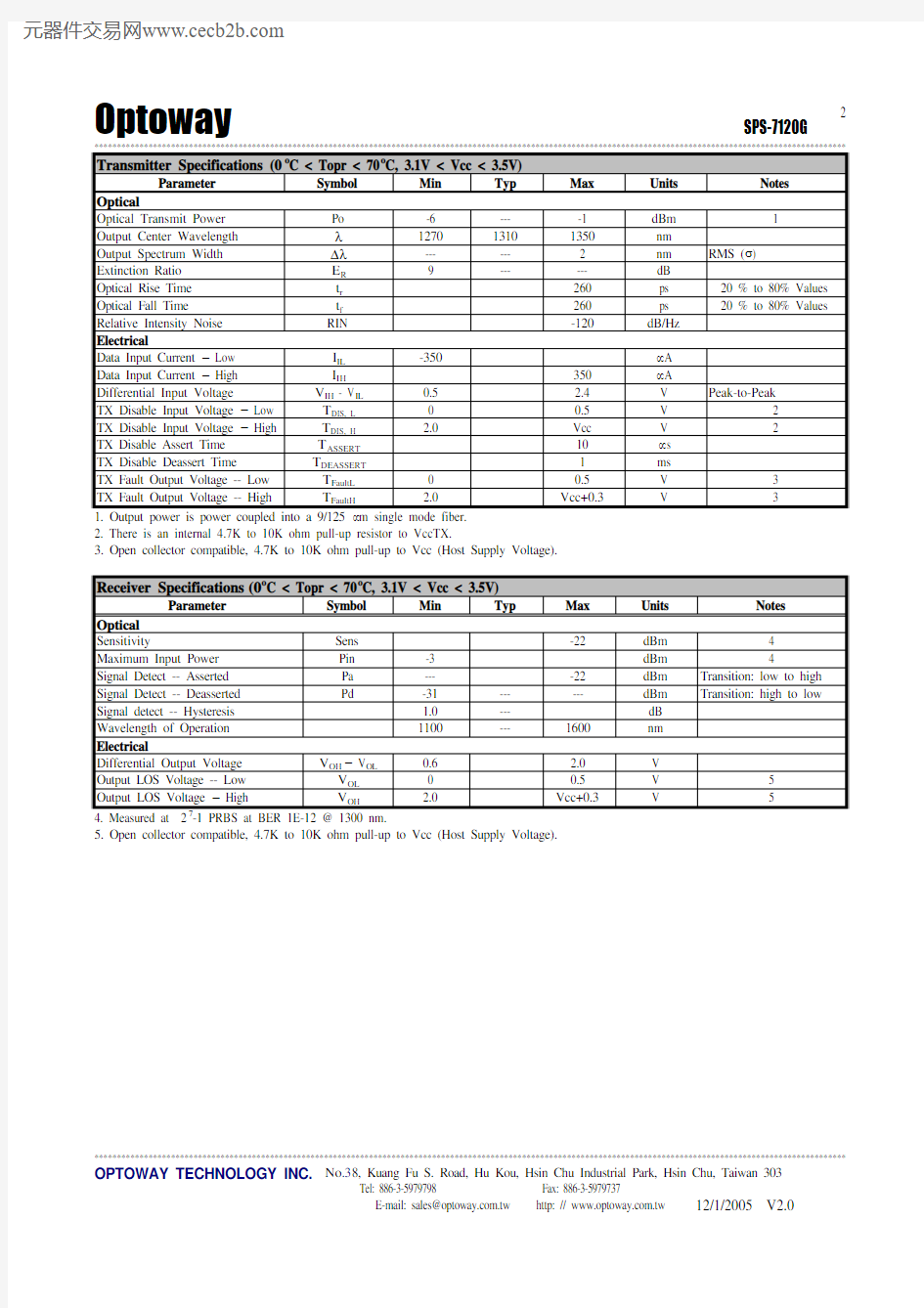
*********************************************************************************************************************************************************************** Transmitter Specifications (0o C < Topr < 70o C, 3.1V < Vcc < 3.5V)
Parameter Symbol Min Typ Max Units Notes
Optical
Optical Transmit Power Po -6 --- -1 dBm 1
Output Center Wavelength λ1270 1310 1350 nm
Output Spectrum Width ?λ--- --- 2 nm RMS (σ)
Extinction Ratio E R9 --- --- dB
Optical Rise Time t r260 ps 20 % to 80% Values Optical Fall Time t f260 ps 20 % to 80% Values Relative Intensity Noise RIN -120 dB/Hz
Electrical
Data Input Current – Low I IL-350 μA
Data Input Current – High I IH350 μA
Differential Input Voltage V IH - V IL0.5 2.4 V Peak-to-Peak
TX Disable Input Voltage – Low T DIS, L0 0.5 V 2
TX Disable Input Voltage – High T DIS, H 2.0 Vcc V 2
TX Disable Assert Time T ASSERT10 μs
TX Disable Deassert Time T DEASSERT 1 ms
TX Fault Output Voltage -- Low T FaultL0 0.5 V 3
TX Fault Output Voltage -- High T FaultH 2.0 Vcc+0.3 V 3
1. Output power is power coupled into a 9/125 μm single mode fiber.
2. There is an internal 4.7K to 10K ohm pull-up resistor to VccTX.
3. Open collector compatible,
4.7K to 10K ohm pull-up to Vcc (Host Supply Voltage).
Receiver Specifications(0o C < Topr < 70o C, 3.1V < Vcc < 3.5V)
Parameter Symbol Min Typ Max Units Notes
Optical
Sensitivity Sens -22 dBm 4
Maximum Input Power Pin -3 dBm 4
Signal Detect -- Asserted Pa --- -22 dBm Transition: low to high Signal Detect -- Deasserted Pd -31 --- --- dBm Transition: high to low Signal detect -- Hysteresis 1.0 --- dB
Wavelength of Operation 1100 --- 1600 nm
Electrical
Differential Output Voltage V OH– V OL0.6 2.0 V
Output LOS Voltage -- Low V OL0 0.5 V 5
Output LOS Voltage – High V OH 2.0 Vcc+0.3 V 5
4. Measured at 2-1 PRBS at BER 1E-12 @ 1300 nm.
5. Open collector compatible, 4.7K to 10K ohm pull-up to Vcc (Host Supply Voltage).
*********************************************************************************************************************************************************************** OPTOWAY TECHNOLOGY INC. No.38, Kuang Fu S. Road, Hu Kou, Hsin Chu Industrial Park, Hsin Chu, Taiwan 303
Tel: 886-3-5979798 Fax: 886-3-5979737
***********************************************************************************************************************************************************************
OPTOWAY TECHNOLOGY INC. No .38, Kuang Fu S. Road, Hu Kou, Hsin Chu Industrial Park, Hsin Chu, Taiwan 303
Tel: 886-3-5979798 Fax: 886-3-5979737
PIN
Signal Name
Description
PIN
Signal Name Description
1 TX GND Transmitter Ground
11 RX GND Receiver Ground
2 TX Fault Transmitter Fault Indication
12 RX DATA OUT- Inverse Receiver Data Out 3 TX Disable Transmitter Disable (Module disables on high or open)
13 RX DATA OUT+ Receiver Data Out 4 MOD-DFE2 Modulation Definition 2 – Two wires serial ID Interface
14 RX GND Receiver Ground
5 MOD-DEF1 Modulation Definition 1 – Two wires serial ID Interface
15 Vcc RX Receiver Power – 3.3V ±5% 6 MOD-DEF0 Modulation Definition 0 – Ground in Module
16 Vcc TX Transmitter Power – 3.3V ±5% 7 N/C Not Connected 17 TX GND
Transmitter Ground 8 LOS Loss of Signal 18 TX DATA IN+ Transmitter Data In
9 RX GND Receiver Ground 19 TX DATA IN- Inverse Transmitter Data In 10
RX GND
Receiver Ground
20
TX GND
Transmitter Ground
Module Definition
Module Definition
MOD-DEF2 PIN 4 MOD-DEF1 PIN 5 MOD-DEF0 PIN 6 Interpretation by Host 4
SDA
SCL
LV-TTL Low
Serial module definition
protocol
Module Definition 4 specifies a serial definition protocol. For this definition, upon power up, MOD-DEF(1:2) appear as no connector (NC) and MOD-DEF(0) is TTL LOW. When the host system detects this condition, it activates the serial protocol. The protocol uses the 2-wire serial CMOS E 2PROM protocol of the ATMEL AT24C01A/02/04 family of components.
*********************************************************************************************************************************************************************** OPTOWAY TECHNOLOGY INC. No.38, Kuang Fu S. Road, Hu Kou, Hsin Chu Industrial Park, Hsin Chu, Taiwan 303
Tel: 886-3-5979798 Fax: 886-3-5979737