永磁直驱风力发电系统的MATLAB建模
Abstract —The paper presents the dynamic model and control schemes of a variable speed pitch wind turbine with permanent magnet synchronous generator (PMSG). The model incl udes a PMSG model, a pitch-angled controlled wind turbine model and a drive train model. The drive train model uses one-mass model
to represent the mechanical characteristics of the generator set.
The generator mode l is estab l ished in the dq –synchronous rotating reference frame. The wind turbine model detail s the mechanism of variable speed operation of the turbine by a pitch control. The control schemes in the paper incl ude a pitch angle
contro l for the wind turbine and a speed contro l for the generator. The pitch angle control uses wind speeds and electric power output as the input signals to ensure normal operation in high wind speed. The speed contro is rea ized through fie d orientation where the d -axis current is set to zero and the q -axis current is used to control the rotational speed of the generator
according to the variation of wind speed. In order to verify the presented mode l and the contro
l strategy, simu l
ations with MATLAB/Simul ink software have been conducted. Simul ation results prove the validity of the model and the control schemes.
Index Terms —Permanent magnet synchronous generator, Wind turbine, Vo l tage source converter, Speed contro l
, Integration I. I NTRODUCTION IT H its abundant, inexhaustible potential, its increasingly competitive cost, and environmental advantage, wind energy is one of the best technologies available today to provide a sustainable supply to the world development. By the end of 2003, the total installed capacity of the wind turbines has reached as much as 39.234GW and will exceed 110GW by the year of 2012 [1]. In depth understanding and investigation of wind energy related technologies, such as wind power generators, wind farm integration, grid code and etc., is very meaningful. In terms of the generators for wind-power application, there are different concepts in use today. The major distinction among them is made between fixed speed and variable speed wind turbine generator concepts. In the early stage of wind power development, fixed-speed wind turbines and induction generators were often used in wind farms. But the limitations of such generators, e.g. low efficiency and poor power quality, This work was supported in part by National Natural Science Foundation
of China under grant 50577018.
The authors are with the Key Laboratory of Power System Protection and Dynamic Security Monitoring and Control under Ministry of Education, North China Electric Power University, Changping 102206, Beijing, P.R.China
(e-mail: routouter@https://www.360docs.net/doc/6c12650910.html,, ligy@https://www.360docs.net/doc/6c12650910.html,, zhouming@https://www.360docs.net/doc/6c12650910.html,,
chengyongzhao@https://www.360docs.net/doc/6c12650910.html,).
adversely influence their further application. With large-scale
exploration and integration of wind sources, variable speed wind turbine generators, such as doubly fed induction generators (DFIGs) and permanent magnetic synchronous generators (PMSGs) are emerging as the preferred technology [2]. In contrast to their fixed-speed counterparts, the variable
speed generators allow operating wind turbines at the optimum tip-speed ratio and hence at the optimum power efficient for a wide wind speed range.
As the penetration of wind power increases, integrating large wind farms to power grids and the relevant influences on the host grids needs to be carefully investigated. So, accurate and reliable model of variable speed wind turbine generators are urgently needed for power system simulation analysis. The paper is dedicated to analyzing the complete model of a variable speed wind turbine with permanent magnet
synchronous generator and developing control schemes for the wind turbine generator. The modeled system consists of a
PMSG model, a pitch-angled controlled wind turbine model and a drive train model. The control schemes include a pitch angle control and a speed control of the generator. The pitch angle control uses wind speed signals and power output of the generator as the inputs. The speed control the concept of
vector control is implemented for the speed control of the
generator in the dq -synchronous rotating reference frame. The
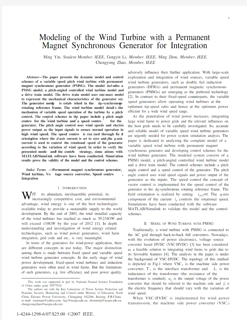
field orientation is realized by setting i dref =0. The q -axis component of the current i q controls the rotational speed. Simulations have been conducted with the software MATLAB/Simulink to validate the model and the control schemes. II. M ODEL OF W IND T URBINE WITH PMSG Traditionally, a wind turbine with PMSG is connected to the AC grid through back-to-back full converters. Nowadays, with the evolution of power electronics, voltage source converter based HVDC (VSC-HVDC) [3] has been considered as a feasible solution to integrating wind farms to grids due to its favorable features [4]. The analysis in the paper is under the background of VSC-HVDC. The topology of this method is depicted in Fig.1 where VSC 1
is the machine side power
converter; T 1 is the interface transformer and L 1
is the
inductance of the transformer (the resistance of the transformer is omitted). u g is the output voltage of the power
converter that should be referred to the machine side and f e is the electric frequency that should vary with the variation of wind speed. When VSC-H VDC is implemented for wind power transmission, the machine side power converter (VSC 1) Modeling of the Wind Turbine with a Permanent Magnet Synchronous Generator for Integration
Ming Yin, Student Member , IEEE , Gengyin Li, Member , IEEE , Ming Zhou, Member , IEEE ,
Chengyong Zhao, Member , IEEE
W
1-4244-1298-6/07/$25.00 ?2007 IEEE.
to VSC2
Fig. 1. Block diagram of PMSG with VSC-HVDC
operates to adjust the speed of the generator according to the variation of wind speed. The power converter (VSC 2) on the other end of the DC Link connects AC grids and takes the onus of controlling the DC voltage and the output AC voltage
or the reactive power [5]. The paper will address the control strategy for the machine-side power converter. A. Aerodynamic Model
The wind turbine extracts power from wind and then
converters it into mechanical power. The amount of aerodynamic torque is related to the wind speed as follows λγθρπ/),(5.023P
w
w
C V R T = (1)
where ρ is the air density, R is the turbine radius, V w is the
wind speed and C P is the power coefficient, θ is the pitch angle of rotor, γ=ωw R/V w is the tip speed ratio and ωw is the turbine rotor speed.
C P can be determined by [6]
βθβ5
.12exp )54.0116(22.0???=p C (2)
where β is calculated by
1035.008.0113
+?+=
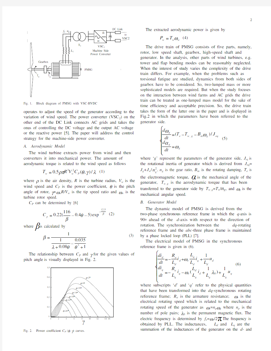
θθλβ (3) The relationship between C P and γ for the given values of
pitch angle is visually displayed in Fig. 2.
γ
C p
Fig. 2. Power coefficient C P (θ, γ) curves.
The extracted aerodynamic power is given by
w w w T P ω= (4)
The drive train of PMSG consists of five parts, namely, rotor, low speed shaft, gearbox, high-speed shaft and generator. In the analysis, other parts of wind turbines, e.g.
tower and flap bending modes can be reasonably neglected.
When the interest of study varies the complexity of the drive train differs. For example, when the problems such as torsional fatigue are studied, dynamics from both sides of gearbox have to be considered. So, two-lumped mass or more sophisticated models are required. But when the study focuses on the interaction between wind farms and AC grids the drive train can be treated as one-lumped mass model for the sake of time efficiency and acceptable precision. So, the drive train takes the form of the latter one in the paper and is displayed in Fig.2 in which the parameters have been referred to the generator side. ???????=??=g g eq g m g w e g
dt
d J B T T dt d ωα
ωω/)(_ (5) where ‘g ’ represent the parameters of the generator side, J eq is the rotational inertia of generator which is derived from J eq =
J g +J w /2
g
n , n g is the gear ratio, B m is the rotating damping, T e is the electromagnetic torque, αg is the mechanical angle of the generator, T w_g is the aerodynamic torque that has been transferred to the generator side by T w_g =T w /n g , and ωg is the mechanical angular speed.
B. Generator Model
The dynamic model of PMSG is derived from the two-phase synchronous reference frame in which the q -axis is 90° ahead of the d -axis with respect to the direction of
rotation. The synchronization between the dq -rotating reference frame and the abc -three phase frame is maintained
by a phase locked loop (PLL) [7]. The electrical model of PMSG in the synchronous reference frame is given in (6). ???????++??=++?=q q q d q d e q q a q d d q d q e d d a d u L L i L L i L R dt
di
u L i L L i L R dt di 1)1(10λωω (6)
where subscripts ‘d ’ and ‘q ’ refer to the physical quantities that have been transformed into the dq -synchronous rotating reference frame; R a is the armature resistance; ωe is the electrical rotating speed which is related to the mechanical rotating speed of the generator as ωe =n p ωg where n p is the number of pole pairs; λ0 is the permanent magnetic flux. The electric frequency is determined by f e =ωe /2π. The frequency is obtained by PLL. The inductances, L d and L q are the summation of the inductances of the generator on the d - and
q -axis and the inductance of the transformer L 1, respectively. u d and u q are, respectively, the d - and q -axis components of u g in Fig.1.
The q -axis counter electric potential e q =ωe λ0 and the d -axis counter electric potential e d =0. In the paper, we assume L d =L q =L and (6) can be rewritten as
???????++??=++?=q d e q a q d q e d a d u L L i i L R dt
di
u L i i L R dt di 1)1(10λωω
Fig.3 shows the equivalent circuit of the PMSG on the
dq -rotating reference frame.
(a) q -axis equivalent circuit
(b) d -axis equivalent circuit
Fig. 3. Equivalent circuit of PMSG in the synchronous frame
The electromagnetic torque can be derived from
))((5.
10λq q d q d p e i i i L L n T +?=As the inductances on the d - and q -axis are equal, the electromagnetic torque can be regulated by i q as
05.1λq p e i n T =Equations (7) can be supplemented by the mechanical
equations for the drive train given in (5) to form the model of PMSG used in this paper.
So, the Simulink based models of the drive train and the generator are given in Fig.4 and Fig.5, respectively.
Fig. 4. Model of the drive train
Fig. 5. Model of the generator
III. C ONTROL S CHEMES
As a type of variable speed wind turbines, PMSGs have two control goals in accordance with variations of wind speeds. In details, in light wind, the maximum power coefficient is maintained by keeping a constant maximum tip speed ratio (power optimization section). In strong wind, the control goal is to keep the machine at the rated output power [8] (power limitation section). In this case, the pitch angle will increase, and the rotor speed will go up and so will the tip speed ratio. According to Fig.3, the power coefficient will drop to maintain the rated output power. The relationships between the generator speed and the electric power and the torque are illustrated in Fig.6.
Speed (pu)
T o r q u e , P o w e r (p u )
Fig. 6. Torque and electric power for different wind speeds.
Meanwhile, the relationship between the power coefficient C P and wind speeds is visualized in Fig.7. There are two control schemes for PMSG to realize the two control goals: pitch control and speed control. The pitch control is implemented to regulate the aerodynamic power extracted from the wind. The pitch angle controller plays the role of a governor in conventional generator, which aims to prevent the generator from exceeding its rated power. This goal is achieved by applying either speed or power feedback. The speed control is utilized to guarantee the machine to follow the predefine speed curve. This goal is achieved by controlling the full power converter on the machine side.
Wind speed (m/s)
P o w e r c o e f f i c i e n t
Fig. 7. Power coefficient C p for different wind speeds.
A. Pitch Angle Control
The pitch angle has significant influence on the power coefficient C P . It plays the role of a governor in conventional generators [9]. In low and medium wind speeds, the pitch control is rarely actuated and only set to the optimum value, e.g. 2°. In high wind speeds, the pitch angle control effects to regulate the extracted wind power so that the design limits of the turbine will not be breached. In the paper, the pitch angle controller is shown in Fig. 8.
Fig. 8. Pitch angle controller
In the pitch angle controller, V wrated is the rated wind speed, e.g. 12m/s. V w is the actual wind speed. P eref is the power
reference value. When power losses are neglected P eref is determined by (1) and (4), i.e. P eref =P w . P e is the actual power which is determined by P e =T e * ωe . The philosophy behind the controller is that wind speed signals are used for feed forward compensation and the power signals for feedback control through a proportional-integral control (PI1 in the figure). In
the controller, “max” is used for selecting the maximum of the
input to ensure that the pitch angle controller actuates only
when the actual wind speed is greater than its rated value.
Therefore, the complete model of wind turbine is obtained, as shown in Fig.9. In the figure, “P_angle control” is the proposed pitch angle controller as in Fig.9; “C P cal” functions to calculate power coefficient according to (2) and (3); “f 1()” aims to calculate ωeref , the reference values of electric angular speed according to (10) [9]. The reference is used to control the speed of PMSG. R n n V p g w eref /γω= (10)
“f 2()” represents the calculation of T w in accordance with (1). In Fig.9, “SW” means a switch that is controlled by wind speed V w . In more detail, when V w is below the rated wind speed, the switch connects to the position “0”; otherwise, to the position “1”.
P V
Fig. 9. Model of the wind turbine
B. Speed Control
As in Fig.1, the full-load frequency converter VSC 1 takes the duty to adjust the rotational speed of the generator that corresponds to the variation of wind speed. The converter generates the voltage phasor u g and the electric frequency f e . So, the machine side converter operates as a voltage source converter.
As the generator is excited by permanent magnets, there is no exchange of reactive power between the generator and the machine side power converter. Therefore, the concept of vector control is implemented for the speed control of the generator in the dq -synchronous rotating reference frame. In
order to obtain field orientation, i dref is set to zero. The torque
command current i qref is derived from the q -axis speed controller. It is known from (6) that there are cross-coupling terms
between the d - and q -axis, namely, ωe i d and ωe i q . Feed forward technique is recommended to compensate the cross-coupling terms. Here, two new inputs and are defined d q e d u Li v +=ω (11)
q q d e q u e Li v +??=ω (12) Therefore, two independent first-order models in the d - and q -axis directions are obtained [10] d a d i R sL v )(+= (13) q a q i R sL v )(+= (14) where s is the Laplace operator. Based on the models, two separate current loops are resulted which have two similar PI controllers designated PI2 and PI3 in Fig. 10. Two control loops are used: the inner loop regulates the currents and the outer loop controls the speed. In the proposed speed controller, i dref =0 and ?ω is the deviation of the electric angular speed from its reference,
namely, ?ω=ωeref ?ωe where ωeref is obtained from the wind turbine model in Fig.9. After the process of the speed
controller, the two generated voltage signals u d and u q are input into the PMSG model as given in (7) to generate the two-axis current components i d and i q , T e , and e q .
d i u d
e q q ?u q
q
q
Fig. 10. Speed controller
So, the model of variable speed wind turbine with PMSG and the proposed control strategy are obtained, which is illustrated in Fig.11. In the figure, “Speed Ctrl” represents the proposed speed controller as shown in Fig.10; “PMSG” is the permanent magnet synchronous generator model; “Drive_T” is the drive train model expressed in (5); “Wind_T” represents the wind turbine model depicted in Fig.9.
Fig. 11. Overall control scheme of wind turbine with PMSG
C. Phase Locked Loop (PLL)
The phase locked loop, in dependence on the sensed value of the angular frequency ω of the AC source and of the phase position of the AC system voltage, generates a synchronizing signal ξ
. The synchronizing signal has the importance in synchronizing the dq -reference plane with the AC source voltage abc -system. Thus, when ξ is in synchronism with the phase of the source voltage, the rotating dq -reference plane is locked and maintained in synchronism with the three-phase abc -system.
IV. S IMULATION S TUDIES
The proposed model of the variable speed wind turbine with PMSG is constructed with MATLAB/Simulink. This
paragraph presents the simulated responses of the system under variable wind speeds. In order to test the proposed model in the paper, a simulation case has been performed with MATLAB/Simulink. In the case, natural wind speed suddenly steps up from 8m/s to
14m/s at t =1s and the reference value of the d -axis current component i dref is set to zero. Simulation results are given in Fig. 12 to Fig. 20.
V w (m /s )
Time (s)
Fig. 12. Wind speed model
P e (M W )
Time (s)
e
Time (s)
Fig. 13. PMSG output power Fig. 14. Electrical rotational speed
P i t c h (o)
Time (s)
T
i p s p e e d r a t i o λ
Time (s)
Fig. 15. Pitch angle Fig. 16. Tip speed ratio
C p
Time (s)
e q (k V )
Time (s)
Fig. 17. Power coefficient Fig. 18. q -axis counter electric potential
i d , i q (A )
Time (s)
Time (s) d q
Fig. 19. dq -axis current components Fig. 20. dq -axis voltage components
It is shown from the simulation results when the wind speed is 8m/s, the initial pitch angle θ keeps the value of 2o, the tip speed ratio γ maintains the optimal value 7, and the
power coefficient C P is the maximum around 0.4.
Just after the wind speed steps from 8m/s to 14m/s, due to the inertia of the wind turbine, the rotational speed can’t keep up with the change of wind speed. Therefore, the tip speed ratio has a drop. Meanwhile, because the wind speed is up the rated wind speed the operation of the pitch angle control is actuated and the pitch angle rises to lower the extracted wind power. At the same time, the rotational speed of the wind turbine goes up, which helps transfer the surplus wind power to mechanical energy. As the rotational speed increases, the q-axis counter electric potential e q increases proportionally, too. As is clearly shown in the equivalent circuit of PMSG (Fig.3), the d- and q-axis components of VSC1’s output voltage u d and u q increases accordingly. So, the performance of the variable speed wind turbine with PMSG can be reasonably explained.
V. C ONCLUSIONS
The paper presents the complete model of the variable speed wind turbine with PMSG that is scheduled to connect an AC grid through VSC-HVDC. The complete model consists of a PMSG model, a pitch-angled controlled wind turbine model and a drive train model. At the same time, the paper addresses control schemes of the wind turbine in terms of pitch angle and generator rotational speed. The pitch angle control is actuated in high wind speeds and uses wind speed signals and electric power as the inputs. The generator rotational speed control scheme features the concept of vector control in the dq-synchronous rotating reference frame. MATLAB/Simulink is implemented to build the dynamic model of the wind turbine with PMSG and simulations have been conducted to validate the model and the proposed control schemes.
From the point of view of integration, comprehensive impact studies should be performed carefully before the wind turbines are added to grids. Under this background, the work in this paper is meaningful.
VI. A PPENDIX
The parameters of the PMSG used in the paper are listed below
Rated power: 2MW;
Rated wind speed: 12m/s;
Resistance: R a=0.1Ohm;
Inductance: L=0.005H;
Gear ratio: n g=77;
Number of pole pairs: n p=2;
Radius of wind turbine rotor: R=41m;
Equivalent inertia: J=8000kg.m2;
Rotational damping: B=0.
VII. A CKNOWLEDGEMENTS
The authors are especially grateful to J. Charles Smith, executive director of UWIG, for his help.
VIII. R EFERENCES
[1] The American Wind Energy Association (2004, March). Global wind
power growth continues to strengthen [Online]. Available: https://www.360docs.net/doc/6c12650910.html,.
[2] J. G. Slootweg, S. W. H. de H aan, H. Polinder, and W. L. Kling,
“aggregated modelling of wind parks with variable speed wind turbines in power system dynamics silulations,” in Proc. 14th Power Sys. Comp.
Conf., Sevilla, Spain, Jun. 2002.
[3] X. Wang and B. T. Ooi, “H igh Voltage Direct Current
transmission system based on Voltage Source Converters,” in Proc. IEEE PESC’90, San Antonio, TX, USA, vol. 1, pp. 325~332, Jun. 1990.
[4] L. Weimers, “H VDC Light: a nEW tECH NOLOGY FOR A bETTER
eNVIRONMEnt,” IEEE Power Review, pp. 19-20, Aug. 1998.
[5] M. Yin, G.Y. Li, G.K. Li, H.F. Liang, and M. Zhou, “Modeling of
VSC-HVDC and control strategies for supplying both active and passive
systems,” Proc. of 2006 IEEE Power Engineering S ociety General Meeting, Jun. 2006, Montreal, Canada.
[6] T. Sun, Z. Chen, and F. Blaabjerg, “Voltage recovery of grid-connected
wind turbines after a short-circuit fault,” in Proc. The 29th Annual Conf.
Of IEEE Ind. Electron. Soc., IECON’03, Roanoke, VA, USA, vol. 3, pp.
2723-2728, Nov. 2003.
[7] S. K. Chung, “Phase-locked loop for grid-connected three-phase power
conversion systems”, IEE Proc. Electr. Power Appl., vol. 147, no. 3, pp.
213-219, May, 2000.
[8] Y. D. Song, B. Dhinakaran, and X. Y. Bao, “Variable speed control of
wind turbines using nonlinear and adaptive algorithms,” Journal of Wind
Engineering and Industrial Aerodynamics, vol. 85, pp. 293-308, Apr.
2000.
[9] S.
H
ier, Grid Integration of Wind Energy Conversion S ystems, John Wiley and sons, 1998.
[10] C. K. Sao, P. W. Lehn, M. R. Iravani, et al. “A benchmark system for
digital time-domain simulation of a pulse-width-modulated D-STATCOM”, IEEE Trans. on Power Delivery, vol. 17, no. 4, pp.
1113-1120, Oct. 2002.
IX. B IOGRAPHIES
Ming Yin (S’06)was born in Hebei Province, China, on April 22, 1974. He received the B.S. degree in power system and its automation from North China Electric Power University (NCEPU) in 1996. Now he is pursuing Ph. D. degree at NCEPU. H is fields of interest include H VDC, wind power technology and flexible AC transmission system (FACTS).
Gengyin Li (M’03)was born in Hebei Province, China. He received the B.S., M.S. and Ph.D. degrees, all in Electrical Engineering, from North China Electric Power University (NCEPU) in 1984, 1987 and 1996, respectively. Since 1987, Dr. Li has been with the School of Electrical Engineering at NCEPU, where he is currently a professor and vice director of the Key Laboratory of Power System Protection and Dynamic Security Monitoring and Control under Ministry of Education. His research interests include power quality, electricity markets, analysis and control of power systems, and new transmission and distribution technologies.
Ming Zhou (S’03, M’06) was born in Hubei Province, China. She received the B.S., M.S. and Ph.D. degrees, all in Electrical Engineering, from North China Electric Power University (NCEPU) in 1989, 1992 and 2006, respectively. Since 1992, Ms. Zhou has been with the School of Electrical Engineering at NCEPU, where she is currently an associate professor. H er areas of interest include electricity markets, power quality, AI applications to power systems, and power system operation and management.
Chengyong Zhao (M’05) was born in Zhejiang Province, China. He received the B.S., M.S. and Ph.D. degrees in power system and its automation from North China Electric Power University (NCEPU) in 1988, 1993 and 2001 respectively. H is fields of interest include power system harmonics, power quality, power electronics and flexible AC transmission system (FACTS).
风力发电系统建模与仿真
风力发电系统建模与仿真 摘要:风力发电作为一种清洁的可再生能源利用方式,近年来在世界范围内获得了飞速的发展。本文基于风力机发电建立模型,主要完成了以下工作:(1)基于风资源特点,建立了以风频、风速模型为基础的风力发电理论基础; (2)运用叶素理论,建立了变桨距风力机机理模型; (3)分析了变速恒频风力发电机的运行区域与变桨距控制的原理与方法,并给出了机组的仿真模型,为风力发电软件仿真奠定了基础; (4)搭建了一套基于PSCAD/EMTDC仿真软件的风力发电系统控制模型以及完整的风力发电样例系统模型,并且已初步实现风力机特性模拟功能。 关键词:风力发电;风频;风速;风力机;变桨距;建模与仿真 1 风资源及风力发电的基本原理 1.1 风资源概述 (1)风能的基本情况[1] 风的形成乃是空气流动的结果。风向和风速是两个描述风的重要参数。风向是指风吹来的方向,如果风是从东方吹来就称为东风。风速是表示风移动的速度即单位时间内空气流动所经过的距离。 风速是指某一高度连续10min所测得各瞬时风速的平均值。一般以草地上空10m高处的10min内风速的平均值为参考。风玫瑰图是一个给定地点一段时间内的风向分布图。通过它可以得知当地的主导风向。 风能的特点主要有:能量密度低、不稳定性、分布不均匀、可再生、须在有风地带、无污染、分布广泛、可分散利用、另外不须能源运输、可和其它能源相互转换等。 (2)风能资源的估算 风能的大小实际就是气流流过的动能,因此可以推导出气流在单位时间内垂直流过单位截面积的风能,即风能密度,表示如下: 3 ω= (1-1) 5.0vρ 式中, ω——风能密度(2 W),是描述一个地方风能潜力的最方便最有价值的量; /m ρ——空气密度(3 kg); /m
直流斩波电路建模仿真
目录 一、降压式直流斩波电路(Buck) (1) 1 原理图 (1) 2 建立仿真模型 (1) 3 仿真波形 (5) 4 小结 (6) 二、升压式直流斩波电路(Boost) (7) 1 原理图 (7) 2建立仿真模型 (7) 3 仿真波形 (8) 4 小结 (9)
一、 降压式直流斩波电路(Buck ) 1 原理图 在控制开关IGBT 导通t on 期间,二极管VD 反偏,电源E 通过电感L 向负载R 供电,此间i L 增加,电感L 的储能也增加,导致在电感两端有一个正向电压Ul=E-u 0,左正右负,这个电压引起电感电流i L 的线性增加。 在控制开关IGBT 关断t off 期间,电感产生感应电势,左负右正,使续流二极管VD 导通,电流i L 经二极管VD 续流,u L =-u 0,电感L 向负载R 供电,电感的储能逐步消耗在R 上,电流i L 线性下降,如此周而复始周期变化。如图1-1。 + -U0E 图1 -1降压式直流斩波电路的电路原理图 2 建立仿真模型 根据原理图用MATLAB 软件画出正确的仿真电路图,如图2。
图1-2降压式直流斩波电路的MATLAB仿真模型 仿真参数,算法(solver)ode15s,相对误差(relativetolerance)1e-3,开始时间0.0结束时间2.0如图1-3。 图1-3 仿真时间参数 电源参数,电压100v,如图1-4。
图1-4 交流电源参数晶闸管参数,如图1-5。 图1-5 晶闸管参数电感参数,如图1-6。 图1-6 电感参数
电阻参数,如图1-7。 图1-7 电阻参数二极管参数设置,如图1-8。 图1-8 二极管参数电容参数设置,如图1-9。
直驱式永磁风力发电系统设计
直驱式永磁风力发电控制系统设计 泮斌斌 (浙江海洋学院机电学院,浙江舟山316000) 摘要 风力发电作为绿色能源在全世界迅速发展,这是解决世界能源危机的重要途径,在这个背景下本文对直驱式永磁风力发电控制系统进行了应用设计。 本文以风力发电的工作原理等基础理论为基本理论,得到一种控制风能的利用效率的变桨控制的基本控制策略;通过比较当前流行的几个风力发电机组的结构和不同控制方案之间的不同特点;分析了直驱式永磁风力发电的性能和特点,最终得出本机组需要采用以“同步高速、无刷励磁旋转、全功率的逆变’’为核心的技术路线。 本论文最后完成了风力发电机控制系统的设计,以控制系统所要实现的功能为基础,根据控制系统的要求,分析了系统输出和输入的信号,简单阐述了组成控制系统的硬件系统的可编程处理器和最主要的控制信号变送器,确定了传感器的类型以及各硬件的配置;以这些为基础讨论了一些控制系统的控制策略,研究设计了主程序的流程图,变桨距控制图,并详细的研究了变桨距的控制过程,得出了控制原理和结构组成。 关键词:风力发电机;控制系统;变桨控制
ABSTRACT Wind power as the rapid development of green energy in the world, it is important to solve the world energy crisis means, in this context of this paper, direct-drive permanent magnet wind power control system for the application design. In this paper, wind power and other basic working principle of the theory of the basic theory, a control variable wind energy utilization efficiency of the basic control strategy for pitch control.A couple of current by comparing the wind turbine structure and the difference between the different characteristics of the control program;Analysis of direct-drive permanent magnet wind power generation performance and features, and ultimately come to the unit needs to adopt a "synchronous high-speed, brushless rotary, full-power inverter technology''as the core line. Finally completed the wind turbine control system to control system functions to be achieved, based on the control system according to the requirements of the system output and input signal composed of a simple control system described in the programmable hardware system The main control signal processor and transmitter, to determine the type of sensors as well as the hardware configuration;Based on these discussions a number of control system control strategy, research and design of the main program flow chart, variable pitch control charts, and detailed study of the pitch control of the process, obtained the control principle and structure. KEY WORDS:wind turbine;control system;pitch control
永磁同步风力发电机的设计说明
哈尔滨工业大学 《交流永磁同步电机理论》课程报告题目:永磁同步风力发电机的设计 院 (系) 电气工程及其自动化 学科电气工程 授课教师 学号 研究生 二〇一四年六月
第1章小型永磁发电机的基本结构 小型风力发电机因其功率低,体积小,一般没有减速机构,多为直驱型。发电机型式多种多样,有直流发电机、电励磁交流发电机、永磁电机、开关磁阻电机等。其中永磁电机因其诸多优点而被广泛采用。 1.1小型永磁风力发电机的基本结构 按照永磁体磁化方向与转子旋转方向的相互关系,永磁发电机可分为径向式、切向式和轴向式。 (1)径向式永磁发电机径向式转子磁路结构中永磁体磁化方向与气隙磁通轴线一致且离气隙较近,漏磁系数较切向结构小,径向磁化结构中的永磁体工作于串联状态,只有一块永磁体的面积提供发电机每极气隙磁通,因此气隙磁密相对较低。这种结构具有简单、制造方便、漏磁小等优点。 径向磁场永磁发电机可分为两种:永磁体表贴式和永磁体内置式。表贴式转子结构简单、极数增加容易、永磁体都粘在转子表面上,但是,这需要高磁积能的永磁体(如钕铁硼等)来提供足够的气隙磁密。考虑到永磁体的机械强度,此种结构永磁电机高转速运行时还需转子护套。内置式转子机械强度较高,但制造工艺相对复杂,制造费用较高。 径向磁场电机用作直驱风力发电机,大多为传统的内转子设计。风力机和永磁体内转子同轴安装,这种结构的发电机定子绕组和铁心通风散热好,温度低,定子外形尺寸小;也有一些外转子设计。风力机与发电机的永磁体外转子直接耦合,定子电枢安装在静止轴上,这种结构有永磁体安装固定、转子可靠性好和转动惯量大的优点,缺点是对电枢铁心和绕组通风冷却不利,永磁体转子直径大,不易密封防护、安装和运输[1]。表贴式和径向式的结构如图1-1 a)所示。 a)径向式结构 b)切向式结构
BUCK电路闭环控制系统的MATLAB仿真..
BUCK 电路闭环PID 控制系统 的MATLAB 仿真 一、课题简介 BUCK 电路是一种降压斩波器,降压变换器输出电压平均值Uo 总是小于输入电压U i 。通常电感中的电流是否连续,取决于开关频率、滤波电感L 和电容C 的数值。 简单的BUCK 电路输出的电压不稳定,会受到负载和外部的干扰,当加入PID 控制器,实现闭环控制。可通过采样环节得到PWM 调制波,再与基准电压进行比较,通过PID 控制器得到反馈信号,与三角波进行比较,得到调制后的开关波形,将其作为开关信号,从而实现BUCK 电路闭环PID 控制系统。 二、BUCK 变换器主电路参数设计 2.1设计及内容及要求 1、 输入直流电压(VIN):15V 2、 输出电压(VO):5V 3、 输出电流(IN):10A 4、 输出电压纹波峰-峰值 Vpp ≤50mV 5、 锯齿波幅值Um=1.5V 6、开关频率(fs):100kHz 7、采样网络传函H(s)=0.3 8、BUCK 主电路二极管的通态压降VD=0.5V ,电感中的电阻压降VL=0.1V ,开关管导通压降 VON=0.5V,滤波电容C 与电解电容 RC 的乘积为 F *Ωμ75
2.2主电路设计 根据以上的对课题的分析设计主电路如下: 图2-1 主电路图 1、滤波电容的设计 因为输出纹波电压只与电容的容量以及ESR 有关, rr rr C L N 0.2V V R i I == ? (1) 电解电容生产厂商很少给出ESR ,但C 与R C 的乘积趋于常数,约为50~80μ*ΩF [3]。在本课题中取为75μΩ*F ,由式(1)可得R C =25mΩ,C =3000μF 。 2、滤波电感设计 开关管闭合与导通状态的基尔霍夫电压方程分别如式(2)、(3)所示: IN O L ON L ON /V V V V L i T ---=?(2) O L D L OFF /V V V L i T ++=? (3) off 1/on s T T f += (4) 由上得: L in o L D on V V V V L T i ---=? (5) 假设二极管的通态压降V D =0.5V ,电感中的电阻压降V L =0.1V ,开关管导通压降V ON =0.5V 。利用ON OFF S 1T T f +=,可得T ON =3.73μS ,将此值回代式(5),可得L =17.5μH
永磁同步风力发电系统实验指导书
永磁同步风力发电系统实验指导书 一、实验目的 1. 学习永磁同步风力发电系统的原理及其组成 2. 学习永磁同步风力发电系统并网过程及并网连续运行过程 3. 了解永磁同步风力发电系统MPPT控制方法与过程 二、实验器材 永磁同步风力发电系统V-Wind-YC、功率分析仪 三、实验内容与步骤 1. 了解整个永磁同步发电系统的组成和各个部分的主要功能(包括异步原动机、永磁同步电机、变频器、双向变流器等)。 2. 掌握永磁同步风力发电系统的并网过程和脱网过程。 (1)系统开机前准备 1)检查供电状态,2)接通控制电源,3)检查通信。 (2)启动网测变流器 在上位机主界面的“网测通讯”区域,点击“启动网测”按钮。 (3)启动风机 在上位机主界面的“变频器通讯”区域,在“给定转速”框中输入转速值,然后点击“启动风机”按钮。 (4)并网运行 在上位机主界面的“机测通讯”区域,点击“并网”按钮,并设置定子有功和定子无功。 (5)脱网 将给定定子有功和无功均设为0,并网输出功率逐渐下降,然后点击“脱网”按钮,脱网完成。 (6)停机 脱网完成后,将给定转速设为0,当风机逐渐停止后,点击“停止风机”按钮,然后点击“网测通讯”区域的“停止网测”按钮,最后关闭主电路旋钮。 3. 掌握永磁同步风力发电系统的自由并网试验。 (1)并网运行 将风机转速设为300r/min,电机转速稳定后,点击“并网”按钮。 (2)低速并网运行 电机转速为300r/min时,手动设定机侧有功功率500W至2000W,记录机侧相电流有效值、网测相电压有效值、网测相电流有效值、机侧有功和网测有功,填入表1中。
(3)额定速并网运行 电机转速设为1000r/min,手动设定机侧有功功率1000W至4000W,记录机侧相电流有效值、网测相电压有效值、网测相电流有效值、机侧有功和网测有功,填入表2中。 (4)离网 离网时,先将机侧给定有功设为0,等待实际功率降为零后,点击“离网”按钮使机侧脱网。 4. 永磁同步风力发电机最大功率跟踪实验 (1)MPPT运行 手动将给定转速设为300r/min,在电机稳定后,进行转子励磁,励磁完成后点击“并网”按钮。成功并网后点击“MPPT”按钮,“MPPT”按钮变绿,此时控制系统按风力机模拟环境运行发电,原动机根据设定的模拟风场特性运行,变流器进行MPPT最大功率跟踪运行。 (2)低速风况模拟 当风速小于12m/s,则风力场最大功率点在运行转速范围之内。此时在跟踪算法控制下,电机转速调整至最大功率点,输出功率为风机在此风速下能输出的最大功率。将基本风设为6m/s,8m/s,10m/s,记录此时电机转速和实时机侧有功功率,填入表3中。 (3)额定转速风况模拟
永磁直驱式风力发电机的工作原理
你好,你的这个问题问的比较广。我大概给你阐述下,对于现在国内国外大型水平轴风力发电机组,有双 馈机和永磁直驱发电机。 永磁直驱发电机顾名思义是在传动链中不含有增速齿轮箱。 总所周知,一般发电机要并网必须满足相位、幅频、周期同步。而我国电网频率为50hz这就表示发电机要发出50hz的交流电。学过电机的都知道。转速、磁极对数、与频率是有关系的n=60f/p。 所以当极对数恒定时,发电机的转速是一定的。所以一般双馈风机的发电机额定转速为1800r/min。而叶轮转速一般在十几转每分。这就需要在叶轮与发电机之间加入增速箱。 而永磁直驱发电机是增加磁极对数从而使得电机的额定转速下降,这样就不需要增速齿轮箱,故名直驱。而齿轮箱是风力发电机组最容易出故障的部件。所以,永磁直驱的可靠性要高于双馈。 对于永磁直驱发电机的磁极部分是用钕铁硼的永磁磁极,原料为稀土。 风轮吸收风能转化为机械能通过主轴传递给发电机发电,发出的电通过全功率变流器之后过升压变压器上网。 不知道有木有解释清楚。 还有什么不清楚可以继续追问,知无不言。 风力发电机也在逐步的永磁化。采用永磁风力发电机,不仅可以提高发电机的效率,而且能在增大电机容量的同时,减少体积,并且因为发电机采用了永磁结构,省去了电刷和集电环等易耗机械部件,提高了系统的可靠性,这也是风电发电机的发展趋势之一。
风力机的直驱化也是当前的一个热点趋势。目前大多风电系统发电机与风轮 并不是直接相连,而是通过变速齿轮相连,这种机械装置不仅降低了系统的效率,增加了系统的成本,而且容易出现故障,是风力发电急需解决的瓶颈问题。直驱式风力发电机可以直接与风轮相连,增加了系统的稳定性,同时增大了电机的体积和设计制造以及控制的难度。直驱型风力发电系统是采用风轮直接驱动多极低速永磁同步发电机发电,通过功率变换电路将电能转换后并入电网,相对于双馈型发电系统,直驱式发电机采用较多的极对数,使得在转速较低时,发电机定子电压输出频率仍然比较高,完全可以在电机的额定等级下工作,并且其定子输出电压通过变流器后再和电网相接,定子频率变化并不会影响电网频率。在直驱风力发电系统中风机与发电机直接耦合,省去了传统风力发电系统中的国内难以自主生产且故障率较高的齿轮箱这一部件,减少了发电机的维护工作,并且降低了噪音。另外其不需要电励磁装置,具有重量轻、效率高、可靠性好的优点。 直驱永磁发电机与双馈异步发电机技术相比,由于不需要转子励磁,没有增速 齿轮箱,效率要比双馈发电机高出20%以上,年发电量要比同容量的双馈机型高;增 速齿轮箱故障较高,维护保养成本高,直驱永磁发电机不需要齿轮箱,易于维修保养;直驱永磁发电机采用全功率的交-直-交变频技术,与电网隔离,具有低电压穿越能力,对电网友好; 直驱永磁发电机的缺点是稀土永磁材料成本高,导致整机成本相对较高,永磁 材料在高温、震动和过电流情况下,有可能永久退磁,致使发电机整体报废,这是直驱永磁发电机的重大缺陷。
风力发电系统建模与仿真
风力发电系统建模与仿真
风力发电系统建模与仿真 摘要:风力发电作为一种清洁的可再生能源利用方式,近年来在世界范围内获得了飞速的发展。本文基于风力机发电建立模型,主要完成了以下工作:(1)基于风资源特点,建立了以风频、风速模型为基础的风力发电理论基 础; (2)运用叶素理论,建立了变桨距风力机机理模型; (3)分析了变速恒频风力发电机的运行区域与变桨距控制的原理与方法,并给出了机组的仿真模型,为风力发电软件仿真奠定了基础; (4)搭建了一套基于PSCAD/EMTDC仿真软件的风力发电系统控制模型以及 完整的风力发电样例系统模型,并且已初步实现风力机特性模拟功能。 关键词:风力发电;风频;风速;风力机;变桨距;建模与仿真 1 风资源及风力发电的基本原理 1.1 风资源概述 (1)风能的基本情况[1] 风的形成乃是空气流动的结果。风向和风速是两个描述风的重要参数。风向是指风吹来的方向,如果风是从东方吹来就称为东风。风速是表示风移动的速度即单位时间内空气流动所经过的距离。 风速是指某一高度连续10min所测得各瞬时风速的平均值。一般以草地上空10m高处的10min内风速的平均值为参考。风玫瑰图是一个给定地点一段时间内的风向分布图。通过它可以得知当地的主导风向。 风能的特点主要有:能量密度低、不稳定性、分布不均匀、可再生、须在有风地带、无污染、分布广泛、可分散利用、另外不须能源运输、可和其它能源相互转换等。 (2)风能资源的估算 风能的大小实际就是气流流过的动能,因此可以推导出气流在单位时间内垂直流过单位截面积的风能,即风能密度,表示如下: 3 ω= (1-1) 5.0vρ 式中, ω——风能密度(2 W),是描述一个地方风能潜力 /m 的最方便最有价值的量;
直流斩波PWM控制Matlab仿真
课程设计任务书 学生姓名:专业班级: 指导教师:工作单位: 题目: 直流斩波PWM控制Matlab仿真 初始条件: 输入200V直流电压。 要求完成的主要任务:(包括课程设计工作量及其技术要求,以及说明书撰写等具体要求) 1、要求得到0~100V直流电压。 2、在Matlab/simulink中建立电路仿真模型; 3、对电路进行仿真; 4、得到结果并对结果进行分析; 时间安排: 课程设计时间为两周,将其分为三个阶段。 第一阶段:复习有关知识,阅读课程设计指导书,搞懂原理,并准备收集设计资料,此阶段约占总时间的20%。 第二阶段:根据设计的技术指标要求选择方案,设计计算。 第三阶段:完成设计和文档整理,约占总时间的40%。 指导教师签名:年月日 系主任(或责任教师)签名:年月日
目录 摘要 (1) 1 概述及设计要求 (2) 1.1 概述 (2) 1.2 设计要求 (2) 2 降压斩波电路拓扑分析 (3) 2.1 降压斩波器基本拓扑 (3) 2.2 buck开关型调整器拓扑分析 (3) 2.3 降压斩波电路的重要参数计算方法 (4) 2.3.1 buck调整器的效率 (4) 2.3.2 buck调整器的理想开关频率 (4) 2.3.3 输出滤波电感的选择 (5) 2.3.4 输出滤波电容的选择 (5) 3 电路设计 (6) 3.1 buck主电路设计 (6) 3.2 脉宽调制电路设计 (7) 3.3 MOS管驱动电路设计 (8) 3.4 系统工作总电路 (8) 4 Matlab建模仿真及分析 (9) 4.1 Matlab仿真模型的建立 (9) 4.2 Matlab仿真结果及分析 (10) 结束语 (14) 参考文献 (15)
750kw风力发电机叶片建模与仿真分析解析
毕业论文题目:750KW风力机叶片建模与模态仿真分析 学院: 专业:机械设计制造及其自动化 班级:学号: 学生姓名: 导师姓名: 完成日期: 2014年6月20日
诚信声明 本人声明: 1、本人所呈交的毕业设计(论文)是在老师指导下进行的研究工作及取得的研究成果; 2、据查证,除了文中特别加以标注和致谢的地方外,毕业设计(论文)中不包含其他人已经公开发表过的研究成果,也不包含为获得其他教育机构的学位而使用过的材料; 3、我承诺,本人提交的毕业设计(论文)中的所有内容均真实、可信。 作者签名:日期:年月日
毕业设计(论文)任务书 题目: 750KW风力机叶片建模与模态仿真分析 姓名学院专业班级学号 指导老师职称教研室主任 一、基本任务及要求: 1、查阅20篇左右文献资料,撰写开题报告和文献综述。 2、确定叶片主要翼形构成、外形参数及载荷。 3、应用三维建模软件建立叶片三维实体模型。 4、应用仿真软件对复合材料叶片进行模态仿真分析。 5、改变叶片转速,讨论复合材料叶片动力刚化效应对振动的影响。 6、按照要求撰写毕业论文和打印图纸。 二、进度安排及完成时间: 2014.2.20-3.5:课题调研(含毕业实习及撰写毕业实习报告)、查阅文献资料。2014.3.6-3.28:撰写文献综述和开题报告。 2014.3.29-4.8:确定叶片主要翼形构成、外形参数及载荷。 2014.4.9-4.19:应用三维建模软件建立叶片三维实体模型。 2014.4.20-4.27:应用仿真软件对复合材料叶片进行模态仿真分析。 2014.4.28-5.5:改变叶片转速,讨论复合材料叶片动力刚化效应对振动的影响。2014.5.6-5.26:撰写毕业论文、完成设计。 2014.5.27-6.10:整理毕业设计资料,毕业答辩。
直流升压变换器的MATLAB仿真
学号 天津城建大学 控制系统仿真 大作业 直流升压变换器的MATLAB仿真 学生姓名 班级 成绩 控制与机械工程学院 2014年6 月20 日
目录 一、绪论1 二、仿真电路原理图及原理1 三、所使用的Matlab工具箱与模块库2 四、模块参数设定2 五、模块封装与仿真框图搭建2 六、仿真结果6 七、结论6 八、参考文献7
一、绪论 在电力电子技术中,将直流电的一种电压值通过电力电子变换装置变换为另一种固定或可调电压值的变换,成为直流-直流变换。直流变换的用途非常广泛,包括直流电动机传动、开关电源、单相功率因数校正,以及用于其它领域的交直流电源。 根据电力电子技术原理,升压式(Boost )斩波器的输出电压0u 高于输入电源电压s u ,控制开关与负载并联连接,与负载并联的滤波电容必须足够大,以保证输出电压恒定,储能电感也要很大,以保证向负载提供足够的能量。 若升压式斩波器的开关导通时间on t ,关断时间off t ,开关工作周期off on t t T +=。定义占空比或导通比/T t D on =,定义升压比S o /U U =α。根据电力电子技术的原理,理论上电 感储能与释放能量相等,有s s off o u 1 u t T β = = U ,升压比的倒数T t 1 off = = α β。还有,1D =+β 。由此可见,当s u 一定时,改变 β就可以调节0u 。当const T =时,调β就 是调off t ,或调on t 也是调β,也就改变了0u ,这就是升压式斩波器的升压工作原理。 二、仿真电路原理图及原理 原理图如图1所示:假设L 值、C 值很大,V 通时,E 向L 充电,充电电流恒为1 I ,同时C 的电压向负载供电,因C 值很大,输出电压0u 为恒值,记为0u 。设V 通的时间为on t ,此阶段L 上积蓄的能量为on 1t EI 。 图1 V 断时,E 和L 共同向C 充电并向负载R 供电。设V 断的时间为off t ,则此期间电感L 释放能量为 ()off 10t I E -u ,稳态时,一个周期T 中L 积蓄能量与释放能量能量相等。化简得 ()off 10on 1t I E -u t EI =,E t T E t t t off off off on o =+=U ,1T/t off ≥,输出电压高于电源电
直驱式永磁同步风力发电机组的建模与仿真
张 梅等:直驱式永磁同步风力发电机组的建模与仿真第6期新能源 直驱式永磁同步风力发电机组的建模与仿真 张 梅1,何国庆2,赵海翔2,张靠社1 (1.西安理工大学电力工程系,陕西西安 710048;2.中国电力科学研究院,北京 100192) 摘要:阐述基于直驱式永磁同步风力发电机组(D-PMSG)的工作原理,在电力系统分析软件DIgSILENT/ PowerFactory中建立了D-PMSG及其控制系统的仿真模型,结合某实际地区电网进行仿真分析。仿真结果 验证了所建模型的正确性和控制策略的可行性。关键词:风力发电;永磁同步发电机;解耦控制中图分类号:TM315 文献标识码:A 文章编号:1004-9649(2008)06-0079-06 中国电力ELECTRICPOWER 第41卷第6期2008 年6月Vol.41,No.6 Jun.2008收稿日期:2008-03-05作者简介:张 梅(1981-),女,陕西西安人,硕士研究生,从事电力系统分析和风力发电研究。E-mail:zhangmei@epri.ac.cn 0引言 风力发电是一种很有潜力的可再生能源,10多 年来得到了快速的发展。目前主流变速风力发电机组有2种:双馈感应风力发电机组和直驱永磁同步风电机组。国内外对基于双馈感应发电机(doubly fedinductiongenerators,DFIG)的变速风力发电技术 的研究很多,已经发展得很成熟。关于直驱永磁同步风力发电机组(D-PMSG)的研究则相对较少,但其以效率高、噪声小、发电机结构简单和维护工作量小等特点,在风力发电领域受到了越来越多的 重视。 目前,对于D-PMSG的建模与仿真是研究的热点。一些文献研究了D-PMSG的建模问题,但比较简单,如文献[1-2]中给出了变频器系统的控制框图,但没有详细论述其解耦控制的原理。文献[3]建立了包括风力机模型、传动系统模型和发电机模型的D-PMSG数学模型, 并提出了桨距角及发电机 转速的控制策略,但忽略了网侧变频器的影响。文献[4-7]采用不同的控制策略,对经由不可控整流和可控逆变电路构成的变频器并网的D-PMSG系统进行了研究, 实现了最大风能跟踪控制及并网 有功和无功功率的解耦控制。文献[8]研究了D- PMSG的桨叶控制及相应的功率和转速的变化过 程。文献[9]建立了基于MTLAB/SIMULINK软件的 D-PMSG仿真模型,对机组的输出特性进行了分 析。文献[10]研究了一种用于D-PMSG并网的中性点箝位变频器系统, 并提出了变频器相应的控 制策略。文献[11]着重分析了双脉宽调制(PWM)D-PMSG发电机侧变频器的控制问题,提出了增加 约束方程来确定发电机端电压的稳定控制方案。这些文献基本集中于风电机组或机组所采用变频器的研究, 没有在实际电网中对模型的特性进行 仿真,不能突出D-PMSG的并网运行特性。 本文介绍了D-PMSG的工作原理,建立了PMSG、变频器模型及轴系的两质块数学模型,提出了全功率变频器的解耦控制策略,实现了有功和无功的解耦控制; 在电力系统仿真软件DIgSILENT/Power Factory中建立了D-PMSG的仿真模型,并结合某 实际地区电网,通过对有功功率突变、调整功率因数设定值以及电网三相短路故障时风电机组的动态响应分析,验证了该模型的正确性和控制策略的可行性。仿真结果较全面地反映了D-PMSG的并网运行特性。 1D-PMSG工作原理 D-PMSG主要包括风力机、PMSG、 全功率变频器以及控制系统4部分,其基本结构如图1所示。其中全功率变频器系统又可分为: 发电机侧变频器 (generator-sideconverter)、 直流环节(DC-link)和电网侧变频器(grid-sideconverter)。 风力机和PMSG通过轴系直接耦合,提高了系统的可靠性,大大减少了系统的运行噪声,降低了发电机的维护工作量。 PMSG经全功率变频器系统与电网相连,通过施加 在变频器系统上的控制系统作用,来实现风电机 组的变速运行。PMSG的输出经发电机侧变频器整 流后由电容支撑,再经网侧变频器将能量馈送给 电网。
风力发电系统建模与仿真
《新能源发电及并网技术》专题报告风力发电系统建模与仿真 学院电气工程学院 专业电气工程 姓名xxxxxxx 学号xxxxxxxxxxxx 2013年6月
目录 1 风资源及风力发电的基本原理 (1) 1.1 风资源概述 (1) 1.2 风力发电的基本原理 (2) 1.3 风力发电特点 (3) 2 风能及风力机系统模型的建立 (3) 2.1风频模型 (3) 2.2 风速模型 (4) 2.3 风力机建模与分析 (5) 3 变桨距风力发电机组控制系统模型 (10) 3.1 变桨距风力发电机组的运行状态 (10) 3.2 变桨距控制系统 (11) 4风力发电控制系统的模拟仿真分析 (13) 4.1 无穷大系统模型的建立 (13) 4.2 风力发电机系统并网模拟仿真分析 (13) 5 结论 (17) 参考文献 (18)
摘要:风力发电作为一种清洁的可再生能源利用方式,近年来在世界范围内获得了飞速的发展。本文基于风力机发电建立模型,建立了以风频、风速模型为基础的风力发电理论基础,运用叶素理论,建立了变桨距风力机机理模型,然后分析了变速恒频风力发电机的运行区域与变桨距控制的原理与方法,并给出了机组的仿真模型,最后搭建了一套基于PSCAD/EMTDC 仿真软件的风力发电系统控制模型以及完整的风力发电样例系统模型,并且已初步实现风力机特性模拟功能。 关键词:风力发电;风频;风速;风力机;变桨距;建模与仿真 1 风资源及风力发电的基本原理 1.1 风资源概述 随着世界工业化进程的不断加快,使得能源消耗逐渐增加,全球工业有害物质的排放量与日俱增,从而造成气候异常、灾害增多、恶性疾病的多发,因此,能源和环境问题成为当今世界所面临的两大重要课题。由能源问题引发的危机以及日益突出的环境问题,使人们认识到开发清洁的可再生能源是保护生态环境和可持续发展的客观需要。可以说,对风力发电的研究和进行这方面的毕业设计对我们从事风力发电事业的同学是有着十分重大的理论和现实意义的,也是十分有必要的。 风力发电起源于20世纪70年代,技术成熟于80年代,自90年代以来风力发电进入了大发展阶段。随着风力发电容量的不断增大,控制方式从基本单一的定桨距失速控制向全桨叶变距控制和变速控制发展。前人在风轮机的空气动力学原理和能量转换原理的基础上,系统分析了定桨距风力发电机组、变桨距风力发电机组、变速风力发电机组的基本控制要求和控制策略,并对并网型风力发电机组的变桨距控制技术进行了一定的研究。变桨距风力发电机组的主要控制是在起动时对风轮转速的控制和并网后对输入功率的控制。通过变距控制可以根据风速来调整桨叶节距角,以满足发电机起动与系统输出功率稳定的双重要求。但由于对运行工况的认识不足,对变桨距控制系统的设计不能满足风力发电机组正常运行的要求,更达不到优化功率曲线和稳定功率输出的要求。 1、风能的基本情况[1] 风的形成乃是空气流动的结果。风向和风速是两个描述风的重要参数。风向是指风吹来的方向,如果风是从东方吹来就称为东风。风速是表示风移动的速度即单位时间内空气流动所经过的距离。
永磁直驱风力发电系统开题报告
毕业设计(论文) 开题报告 题目:永磁直驱风电系统动态特性仿真研究 学院专业 学号: 学生姓名: 指导教师:(职称:) (职称:) 2016年 3 月15 日 1、课题来源及选题的理由或意义: 课题来源:导师定题 选题理由: 随着全球经济的快速发展,环境和资源问题越来越严重,实现能源的可持续发展与再生利用已成为必须解决的问题。风能作为一种清洁的可再生能源越来越受人类重视。风力发电作为一种风能的主要利用形式正飞速发展,风力发电代替传统能源发电的比例正逐步上升,并在电力越来越受重视。 目前大多数风电系统采用的双馈发电机具有齿轮箱,与其相比,直驱式永磁同步风电机组是风力机与发电机直接相连,减小了齿轮箱带来的机械损耗和设备的不稳定性,从而大大提高了可靠性,降低了维护费用。且具有结构简单,转换效率高,控制灵活等特点,发展较好,在风力发电系统中越来越受到欢迎。大型永磁同步风力发电机组已成为目前兆瓦级大型风电场所采用的主流风电机组。 2、研究内容及拟解决的关键问题: 主要内容: 以直驱式永磁风力发电系统作为研究对象,通过研究风力机和永磁同步发电机各自的特性和运行机理,建立永磁直驱风力发电系统的数学模型,包括风速模型、风力机模型、永磁同步发电机模型和控制系统模型等,对风速变化时机组运行情况进行仿真。通过Matlab/Simulink对风速、风力机、永磁同步发电机等实现模型搭建,最终建成整个风力发电系统模型,进行仿真得出结果。 关键问题: 1. 建立准确的风速模型、风轮模型、风力机模型以及直驱式永磁同步发电系统(PMSG)模型; 2. 设计出永磁直驱风电系统的控制器; 3. 使用Matlab/Simulink仿真来验证设计的正确性和可行性; 3、国内外研究现状: 1. 国内外风电产业发展状况 美国是世界上最早重视风力发电的国家之一。1994年,美国的装机容量是163万千瓦,占当年全球风电装机容量的53%。到2000年,形成了40亿美元的风机产业,每年至少可交付30 万千瓦的风电机组产品。预计到2050年,全美风力发电将占全国电力的10%。欧洲是风力发电发展较快的地区,其中以丹麦和德国为代表。丹麦是世界风力发电的先进国家和风力发电机主要制造国之一。1978年丹麦成立了国立风力发电试验站,促使了风力机工业
升、降压直流斩波电路及matlab仿真
目录 绪论 (3) 一.降压斩波电路 (6) 二.直流斩波电路工作原理及输出输入关系 (12) 三.D c/D C变换器的设计 (18) 四.测试结果 (19) 五.直流斩波电路的建模与仿真 (29) 六.课设体会与总结 (30) 七.参考文献 (31)
绪论 1. 电力电子技术的内容 电力电子学,又称功率电子学(Power Electronics)。它主要研究各种电力电子器件,以及由这些电力电子器件所构成的各式各样的电路或装置,以完成对电能的变换和控制。 它既是电子学在强电(高电压、大电流)或电工领域的一个分支,又是电工学在弱电(低电压、小电流)或电子领域的一个分支,或者说是强弱电相结合的新科学。电力电子学是横跨“电子”、“电力”和“控制”三个领域的一个新兴工程技术学科。 电有直流(DC)和交流(AC)两大类。前者有电压幅值和极性的不同,后者除电压幅值和极性外,还有频率和相位的差别。 实际应用中,常常需要在两种电能之间,或对同种电能的一个或多个参数(如电压,电流,频率和功率因数等)进行变换。 变换器共有四种类型: 交流-直流(AC-DC)变换:将交流电转换为直流电。 直流-交流(DC-AC)变换:将直流电转换为交流电。这是与整流相反的变换,也称为逆变。当输出接电网时,称之为有源逆变;当输出接负载时,称之为无源逆变。 交-交(AC-AC)变换,将交流电能的参数(幅值或频率)加以变换。其中:改变交流电压
有效值称为交流调压;将工频交流电直接转换成其他频率的交流电,称为交-交变频。直流-直流(DC-DC)变换,将恒定直流变成断续脉冲输出,以改变其平均值。 2. 电力电子技术的发展 在有电力电子器件以前,电能转换是依靠旋转机组来实现的。与这些旋转式的交流机组比较,利用电力电子器件组成的静止的电能变换器,具有体积小、重量轻、无机械噪声和磨损、效率高、易于控制、响应快及使用方便等优点。 1957年第一只晶闸管—也称可控硅(SCR)问世后,因此,自20世纪60年代开始进入了晶闸管时代。 70年代以后,出现了通和断或开和关都能控制的全控型电力电子器件(亦称自关断型器件),如:门极可关断晶闸管(GTO)、双极型功率晶体管(BJT/ GTR)、功率场效应晶体管(P-MOSFET)、绝缘栅双极型晶体管(IGBT)等。 控制电路经历了由分立元件到集成电路的发展阶段。现在已有专为各种控制功能设计的专用集成电路,使变换器的控制电路大为简化。 微处理器和微型计算机的引入,特别是它们的位数成倍增加,运算速度不断提高,功能不断完善,使控制技术发生了根本的变化,使控制不仅依赖硬件电路,而且可利用软件编程,既方便又灵活。 各种新颖、复杂的控制策略和方案得到实现,并具有自诊断功能,并具有智能化的功能。将新的控制理论和方法应用在变换器中。 综上所述可以看出,微电子技术、电力电子器件和控制理论则是现代电力电子技术的发展动力。 3.电力电子技术的重要作用 (1) 优化电能使用。通过电力电子技术对电能的处理,使电能的使用达到合理、高效
基于-matlab的风力发电机组的建模和仿真
实验一 :风力发电机组的建模与仿真 : 学号: 一、实验目标: 1.能够对风力发电机组的系统结构有深入的了解。 2.能熟练的利用MATLAB 软件进行模块的搭建以及仿真。 3.对仿真结果进行研究并找出最优控制策略。 二、实验类容: 对风速模型、风力机模型、传动模型和发电机模型建模,并研究各自控制方法及控制策略;如对风力发电基本系统,包括风速、风轮、传动系统、各种发电机的数学模型进行全面分析,探索风力发电系统各个部风最通用的模型、包括了可供电网分析的各系统的简单数学模型,对各个数学模型,应用 MATLAB 软件进行了仿真。 三、实验原理: 风力发电系统的模型主要包括风速模型、传动系统模型、发电机模型和变桨距模型,下文将从以上几方面进行研究。 1、风速的设计 自然风是风力发电系统能量的来源,其在流动过程中,速度和方向是不断变化的,具有很强的随机性和突变性。本文不考虑风向问题,仅从其变化特点出发,着重描述其随机性和间歇性,认为其时空模型由以下四种成分构成:基本风速b V 、阵风风速 g V 、渐变风速 r V 和噪声风速 n V 。 即模拟风速的模型为: V=b V +g V +r V +n V (1-1) (1). 基本风b V =8m/s 基本风仿真模块 (2)阵风风速 ? ?? ??=0 cos v g V g g g g g g T t t T t t t t t +>+<<<1111 (1-2) 式中: ??? ?????--=)(2cos 121max cos g g g T t T t G v π (1-3) t 为时间,单位 s ;T 为阵风的周期,单位 s ;cos v ,g V 为阵风风速,单位m /s ;g t 1为阵风开始时间,单位 s ;max G 为阵风的最大值,单位 m/s 。
永磁同步风力发电系统的组成、工作原理及控制机理
永磁同步风力发电系统的系统基本组成、工作原理、控制 模式论述 1.系统的基本组成: 直驱式同步风力发电系统主要采用如下结构组成:风力机(这里概括为:叶片、轮毂、导航罩)、变桨机构、机舱、塔筒、偏航机构、永磁同步发电机、风速仪、风向标、变流器、风机总控系统等组成。其中全功率变流器又可分为发电机侧整流器、直流环节和电网侧逆变器。就空间位置而言,变流器和风机总控系统一般放在塔筒底部,其余主要部件均位于塔顶。 2.工作原理: 系统中能量传递和转换路径为:风力机把捕获的流动空气的动能转换为机械能,直驱系统中的永磁同步发电机把风力机传递的机械能转换为频率和电压随风速变化而变化的不控电能,变流器把不控的电能转换为频率和电压与电网同步的可控电能并馈入电网,从而最终实现直驱系统的发电并网控制。 3.控制模式: 风力发电机组的控制系统是综合性控制系统。它不仅要监视电网、风况和机组运行参数,对机组运行进行控制。而且还要根据风速与风向的变化,对机组进行优化控制,以提高机组的运行效率和发电量。 风力发电控制系统的基本目标分为三个层次: 分别为保证风力发电机组安全可靠运行,获取最大能量,提供良好的电力质量。 控制系统主要包括各种传感器、变距系统、运行主控制器、功率输出单元、无功补偿单元、并网控制单元、安全保护单元、通讯接口电路、监控单元。 具体控制内容有:信号的数据采集、处理,变桨控制、转速控制、自动最大功率点跟踪控制、功率因数控制、偏航控制、自动解缆、并网和解列控制、停机制动控制、安全保护系统、就地监控、远程监控。
一、系统运行时控制: 1、偏航系统控制: 偏航系统的控制包括三个方面:自动对风、自动解缆和风轮保护。 1)自动对风 正常运行时偏航控制系统自动对风,即当机舱偏离风向一定角度时,控制系统发出向左或向右调向的指令,机舱开始对风,当达到允许的误差范围内时,自动对风停止。 2)自动解缆 当机舱向同一方向累计偏转2~3圈后,若此时风速小于风电机组启动风速且无功率输出,则停机,控制系统使机舱反方向旋转2~3圈解绕;若此时机组有功率输出,则暂不自动解绕;若机舱继续向同一方向偏转累计达3圈时,则控制停机,解绕;若因故障自动解绕未成功,在扭缆达4圈时,扭缆机械开关将动作,此时报告扭缆故障,自动停机,等待人工解缆操作。3)风轮保护 当产生特大强风时,停机并释放叶尖阻尼板,桨距调到最大,偏航90°背风,以保护风轮免受损坏。 2、变桨距系统控制 变桨系统的控制包括三个方面:启动状态(转速控制)、欠功率状态(不控制)和额定功率状态(功率控制)。 1)起动状态 桨叶在静止时,节距角为90°,这时气流对桨叶不产生转矩,整个桨叶实际上是一块阻尼板。当风速达到启动风速时,桨叶向0°方向转动,知道气流对桨叶产生一定的攻角,风轮开始起动。在发电机并入电网以前,变桨距系统的节距给定值由发电机转速信号控制。转速控制器按照一定的速度上升斜率给出速度参考值。为确保并网平稳,对电网产生的冲击尽可能小,变桨距系统可以在一定时间内,保持发电机的转速在同步转速附近。 2)欠功率状态 当风速低于额定风速时,发电机在额定功率以下工作,此时变桨距系统不加控制,节距角为0,以实现最大功率跟踪。 3)额定功率状态 当风速达到或超过额定风速后,风力发电机进入额定功率状态。变桨距系统根据发电机的功率信号进行控制。 3、机侧变流器的控制 永磁同步发电机侧变流器的控制目标是: 1)将永磁同步发电机发出的频率和电压幅值变化无序的交流电整流成直流电 2)控制风力机转速,实现最大风能捕获 3)控制与永磁同步发电机间的无功交换。 4、网侧变流器的控制 网侧变流器可以工作在整流和逆变状态,一般情况下在单位功率因数逆变运行。此时,能量由直流侧流向电源,且无功功率为零。 网侧逆变器控制目标是: 1)将直流电逆变为与电网频率、幅值相同的交流电,保证电网侧电流正弦,减少谐波对电网的污染并维持直流侧电压恒定,提高发电效率。