冲压模具设计成型方面毕业设计外文翻译
毕业设计(论文)英文翻译
课题名称
系部材料工程系
专业材料成型及控制工程
班级
学号
姓名
指导教师
2 0 10年
3 月 10日
4 Sheet metal forming and blanking
4.1 Principles of die manufacture
4.1.1 Classification of dies
In metalforming,the geometry of the workpiece is established entirely or partially by the geometry of the die.In contrast to machining processes,ignificantly greater forces are necessary in forming.Due to the complexity of the parts,forming is often not carried out in a single operation.Depending on the geometry of the part,production is carried out in several operational steps via one or several production processes such as forming or blanking.One operation can also include several processes simultaneously(cf.Sect.2.1.4).
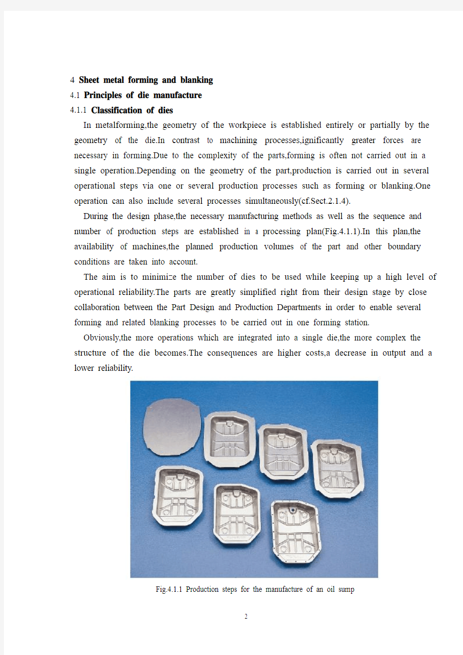
During the design phase,the necessary manufacturing methods as well as the sequence and number of production steps are established in a processing plan(Fig.4.1.1).In this plan,the availability of machines,the planned production volumes of the part and other boundary conditions are taken into account.
The aim is to minimize the number of dies to be used while keeping up a high level of operational reliability.The parts are greatly simplified right from their design stage by close collaboration between the Part Design and Production Departments in order to enable several forming and related blanking processes to be carried out in one forming station.
Obviously,the more operations which are integrated into a single die,the more complex the structure of the die becomes.The consequences are higher costs,a decrease in output and a lower reliability.
Fig.4.1.1 Production steps for the manufacture of an oil sump
Types of dies
The type of die and the closely related transportation of the part between dies is determined in accordance with the forming procedure,the size of the part in question and the production volume of parts to be produced.
The production of large sheet metal parts is carried out almost exclusively using single sets of dies.Typical parts can be found in automotive manufacture,the domestic appliance industry and radiator production.Suitable transfer systems,for example vacuum suction systems,allow the installation of double-action dies in a sufficiently large mounting area.In this way,for example,the right and left doors of a car can be formed jointly in one working stroke(cf.Fig.4.4.34).
Large size single dies are installed in large presses.The transportation of the parts from one forming station to another is carried out mechanically.In a press line with single presses installed one behind the other,feeders or robots can be used(cf.Fig.4.4.20 to 4.4.22),whilst in large-panel transfer presses,systems equipped with gripper rails(cf.Fig.4.4.29)or crossbar suction systems(cf.Fig.4.4.34)are used to transfer the parts.
Transfer dies are used for the production of high volumes of smaller and medium size parts(Fig.4.1.2).They consist of several single dies,which are mounted on a common base plate.The sheet metal is fed through mostly in blank form and also transported individually from die to die.If this part transportation is automated,the press is called a transfer press.The largest transfer dies are used together with single dies in large-panel transfer presses(cf.Fig.4.4.32).
In progressive dies,also known as progressive blanking dies,sheet metal parts are blanked in several stages;generally speaking no actual forming operation takes place.The sheet metal is fed from a coil or in the form of metal https://www.360docs.net/doc/7210328315.html,ing an appropriate arrangement of the blanks within the available width of the sheet metal,an optimal material usage is ensured(cf.Fig.4.5.2 to 4.5.5). The workpiece remains fixed to the strip skeleton up until the la
Fig.4.1.2 Transfer die set for the production of an automatic transmission for an automotive application
-st operation.The parts are transferred when the entire strip is shifted further in the work flow direction after the blanking operation.The length of the shift is equal to the center line spacing of the dies and it is also called the step width.Side shears,very precise feeding devices or pilot pins ensure feed-related part accuracy.In the final production operation,the finished part,i.e.the last part in the sequence,is disconnected from the skeleton.A field of application for progressive blanking tools is,for example,in the production of metal rotors or stator blanks for electric motors(cf.Fig.4.6.11 and 4.6.20).
In progressive compound dies smaller formed parts are produced in several sequential operations.In contrast to progressive dies,not only blanking but also forming operations are performed.However, the workpiece also remains in the skeleton up to the last operation(Fig.4.1.3 and cf.Fig.4.7.2).Due to the height of the parts,the metal strip must be raised up,generally using lifting edges or similar lifting devices in order to allow the strip metal to be transported mechanically.Pressed metal parts which cannot be produced within a metal strip because of their geometrical dimensions are alternatively produced on transfer sets.
Fig.4.1.3 Reinforcing part of a car produced in a strip by a compound die set
Next to the dies already mentioned,a series of special dies are available for special individual applications.These dies are,as a rule,used separately.Special operations make it possible,however,for special dies to be integrated into an operational Sequence.Thus,for example,in flanging dies several metal parts can be joined together positively through the bending of certain metal sections(Fig.4.1.4and cf.Fig.2.1.34).During this operation reinforcing parts,glue or other components can be introduced.
Other special dies locate special connecting elements directly into the press.Sorting and positioning elements,for example,bring stamping nuts synchronised with the press cycles into the correct position so that the punch heads can join them with the sheet metal part(Fig.4.1.5).If there is sufficient space available,forming and blanking operations can be carried out on the same die.
Further examples include bending,collar-forming,stamping,fine blanking,wobble blanking and welding operations(cf.Fig.4.7.14 and4.7.15).
Fig.4.1.4 A hemming die
Fig.4.1.5 A pressed part with an integrated punched nut
4.1.2 Die development
Traditionally the business of die engineering has been influenced by the automotive industry.The following observations about the die development are mostly related to body panel die construction.Essential statements are,however,made in a fundamental context,so that they are applicable to all areas involved with the production of sheet-metal forming and blanking dies.
Timing cycle for a mass produced car body panel
Until the end of the 1980s some car models were still being produced for six to eight years more or less unchanged or in slightly modified form.Today,however,production time cycles are set for only five years or less(Fig.4.1.6).Following the new different model policy,the demands ondie makers have also changed https://www.360docs.net/doc/7210328315.html,prehensive contracts of much greater scope such as Simultaneous Engineering(SE)contracts are becoming increasingly common.As a result,the die maker is often involved at the initial development phase of the metal part as well as in the planning phase for the production process.Therefore,a much broader involvement is established well before the actual die development is initiated.
Fig.4.1.6 Time schedule for a mass produced car body panel
The timetable of an SE project
Within the context of the production process for car body panels,only a minimal amount of time is allocated to allow for the manufacture of the dies.With large scale dies there is a run-up period of about 10 months in which design and die try-out are included.In complex SE projects,which have to be completed in 1.5 to 2 years,parallel tasks must be carried out.Furthermore,additional resources must be provided before and after delivery of the dies.These short periods call for pre-cise planning,specific know-how,available capacity and the use of the latest technological and communications systems.The timetable shows the individual activities during the manufacturing of the dies for the production of the sheet metal parts(Fig.4.1.7).The time phases for large scale dies are more or less similar so that this timetable can be considered to be valid in general.
Data record and part drawing
The data record and the part drawing serve as the basis for all subsequent processing steps.They describe all the details of the parts to be produced. The information given in the
Fig.4.1.7 Timetable for an SE project
part drawing includes: part identification,part numbering,sheet metal thickness,sheet metal quality,tolerances of the finished part etc.(cf.Fig.4.7.17).
To avoid the production of physical models(master patterns),the CAD data should describe the geometry of the part completely by means of line,surface or volume models.As a general rule,high quality surface data with a completely filleted and closed surface geometry must be made available to all the participants in a project as early as possible.
Process plan and draw development
The process plan,which means the operational sequence to be followed in the production of the sheet metal component,is developed from the data record of the finished part(cf.Fig.4.1.1).Already at this point in time,various boundary conditions must be taken into account:the sheet metal material,the press to be used,transfer of the parts into the press,the transportation of scrap materials,the undercuts as well as the
sliding pin installations and their adjustment.
The draw development,i.e.the computer aided design and layout of the blank holder area of the part in the first forming stage–if need bealso the second stage–,requires a process planner with considerable experience(Fig.4.1.8).In order to recognize and avoid problems in areas which are difficult to draw,it is necessary to manufacture a physical analysis model of the draw development.With this model,the
forming conditions of the drawn part can be reviewed and final modifications introduced,which are eventually incorporated into the data record(Fig.4.1.9).
This process is being replaced to some extent by intelligent simulation methods,through
which the potential defects of the formed component can be predicted and analysed interactively on the computer display.
Die design
After release of the process plan and draw development and the press,the design of the die can be started.As a rule,at this stage,the standards and manufacturing specifications required by the client must be considered.Thus,it is possible to obtain a unified die design and to consider the particular requests of the customer related to warehousing of standard,replacement and wear parts.Many dies need to be designed so that they can be installed in different types of presses.Dies are frequently installed both in a production press as well as in two different separate back-up presses.In this context,the layout of the die clamping elements,pressure pins and scrap disposal channels on different presses must be taken into account.Furthermore,it must be noted that drawing dies working in a single-action press may be installed in a double-action press(cf.Sect.3.1.3 and Fig.4.1.16).
Fig.4.1.8 CAD data record for a draw development
In the design and sizing of the die,it is particularly important to consider the freedom of movement of the gripper rail and the crossbar transfer elements(cf.Sect.4.1.6).These describe the relative movements between the components of the press transfer system and the die components during a complete press working stroke.The lifting movement of the press slide,the opening and closing movements of the gripper rails and the lengthwise movement of the whole transfer are all superimposed.The dies are designed so that collisions are avoided and a minimum clearance of about 20 mm is set between all the moving parts.
4 金属板料的成形及冲裁
4. 模具制造原理
4.1.1模具的分类
在金属成形的过程中,工件的几何形状完全或部分建立在模具几何形状的基础上的。与机械加工相比,在成形时明显更大的压力是必要的。由于零件的复杂性,往往不是只进行一次操作就能成形的。根据零件的几何形状,通过由一个或几个生产过程例如成形或冲裁的几个操作步骤进行生产。一个操作也可以同时完成几个过程。
在设计阶段,合理的生产步骤、生产次序以及生产工序数都由生产计划来决定(如图4.1.1)。在这个计划中,应该对机器的可利用性、零件的计划生产量和其他限制条件予以考虑。
其目的是在保证高水平的操作可靠性的同时最大限度地减少需要使用的模具数量。通过部件设计部和生产部之间的紧密合作促使几个成形和有关的冲裁过程能在一个成形操作中完成,如此一来,仅仅在设计阶段就可以大大地简化部件。
显然,越是更多的操作集成到一个单独的模具上,模具结构就必然更为复杂。其后果是成本较高、产量下降和可靠性较低。
图4.1.1 油底壳的生产步骤
模具类型
模具的类型和模具之间零部件的密切相关运输是根据成形步骤、预算的部件的尺寸、要生产的部件的生产量来确定的。
大型钣金零件的生产几乎完全采用单套模具来实现的。典型零件可在汽车制造、国内家电业以及散热器的生产中找到。适当的转移系统,例如真空抽吸系统,可以使双动模安装在一个足够大的安装面上。例如,用这种方式可以使汽车左右车门在一个工作行程中一起成形。(参考图4.4.34)。
尺寸大的单套模具需安装在大型压力机上。部件从一个成形点到另一个成形点的运输是机械化地执行的。工人或机器人可以使用与单工序压力机一前一后安装的冲压线(对比图4.4.20与 4.4.22),同时,在大型多工位压力机上,系统还配备了夹钳轨(如图4.4.29)或交叉抽吸系统(如图4.4.34)来运输部件。
多工位转换模是用于小型和中型零件的大批量生产(如图4.1.2)。它们由几个安装在同一个基准平面上的单工序模具组成。金属板料的送进主要以机械手运送的方式,也可以人工地从一个模具运到另一个模具。如果这部分的运输自动化,那么此时的压力就称为转换压力。在大板料转换冲压线上,最大的多工位转换模要与单工序模具配合使用(参考图4.4.32)。
级进模,也称为渐进冲裁模,钣金件是分阶段冲裁的;一般来说,没有实实在在的成形操作。钣金是以金属圈或金属条的形式送进的。通过使用尺寸适宜的金属板料和优化的材料利用率可以达到对板料的合理利用(对比图Fig.4.5.2与图4.5.5)。工件一直固定在载体上,直到最后一次操作。冲裁完成后,整个条料按照工序流动方向移动时,该部件随着转移。移动的长度等于模具间中心线的距离,它也被称为步距。切边,通过使用非常精确的进给装置或试点引脚确保相关进给零件精度。在最后一个工位,即最后一道工序,已成形的部分于载体断开。例如电动机金属转子和定子的生产就是渐进冲裁模的一个应用领域(如图.4.6.11和4.6.20)。
图4.1.2转移成套模具在机动装置中的自动变速器上生产应用
较小的成形部件使用复合级进模通过几个连续的操作即可完成后生产。与级进模相比,不仅可以完成冲裁,而且能完成成形操作。然而,工件还是与载体相连一直到最后一步操作(如图4.1.3和对比图4.7.2)。由于零件的高度,钢带必须提高时,通常使用起重边缘或类似的起重设备,以便实现条料金属的机械化运输。由于其几何尺寸而不能用一个金属条料生产出来的冲压金属零件选择性地在转移设置上生产。
图4.1.3 用一个条料在复合级进模上生产的汽车加强筋
接下来时已经提到过的模具,一系列特殊模具适用于个别特殊运用。按规定,这些
模具是单独使用的。但是,特殊的操作使得特殊的模具集成到一个工序上成为可能。因此,例如,使用翻边模几个金属部件组合在一起能积极通过某些区域的弯曲(如图4,1,4和对比图2,1,34)。在此期间加强部分,胶水或其他组件的运作可实施。
其他的特殊模具使特殊的连接部件直接定位在压力机上。装配和定位部件,例如,引进与压力周期同步的冲头到指定的位置以便冲头与钣金零件(如图4.1.5)。如果有足够的可用空间,成形和冲裁操作可以在同一模具上完成。
更一步的例子包括弯曲,滚压成形,冲压,精密冲裁,震动冲裁和焊接操作(对比图4.7.14和图4.7.15)。
如图4.1.4卷边模
如图4.1.5带有整体冲压螺母的冲压件
4.1.2 模具开发
汽车行业的发展已经必然地影响了模具工程的发展。以下对与模具开发的研究主要是关于车身覆盖件模具结构的。然而,用一个基本的环境获得实质的结论,以便于它们适用于包括钣金成形模和冲裁模的制造在内的所有领域。
为汽车覆盖件的大批量生产定时生产周期
直到20世纪80年代末,部分车型以6至8年大致维持不变或略加修改的形式而仍然处于制作中。然而今天,生产周期只有5年或更少(如图4.1.6)。随着不同的新设计工艺的发展,客户对模具制造商的要求也发生了根本变化。更大范围的综合合同,如同步工程(SE)合同已变得越来越普遍。结果是,模具制造商往往仅处于金属零件的最初的发展阶段,以及生产过程的规划阶段。因此,在实际模具开发和启动之前应该拓展更广泛、长远的业务。
图4.1.6 汽车覆盖件的大批量生产的时间表
同步工程项目时间表
在车身覆盖件的生产过程中,只有极少部分时间用于模具的制造。对于大型模具,大约有十个月的准备期,其中包括模具的设计与调试。对于复杂的同步工程项目中,必
须在1.5至2年内完成,必须能完成同步任务。此外,在模具交付前后必须具有更多的
产品资料说明。这些短期的准备需要优化的设计、特别的技能、可利用空间以及最新技术的使用和通讯系统。该时间表显示,用于生产钣金件的模具的制造期间的个人工作内容(如图4.1.7)。大型模具的生产计划或多或少都相似,以便于这个时间表可以被认为是普遍有效的。
图4.1.7 同步工程项目时间表
数据采集和零件图
数据采集和零件图是所有工序步骤的基础。它们描述了要生产部件的所有细节。在零件图提供的信息包括:零件识别,部件的编号,板材厚度,板材的质量,成品零件的公差等(参考图4.7.17)。
为了避免实体模型(主模型)的制作,CAD图形应通过线、面或体积模型来完整地描述工件的几何形状。一般地,必须尽可能早地绘制好具有完全封闭曲面的高质量片体数模来满足所有产品负责人的使用要求。
工艺方案和制图计划
工艺方案,即生产钣金件应遵循的操作顺序,是根据以往生产出的零件的经验数据制定的(参考图4.1.1)。在此阶段,必须提前及时考虑到各种边界条件:金属板材料,所需压力,零件的加工硬化,废料的排出,废料刀以及导料销的安装和调试。
制图计划,即计算机辅助设计和第一个成形阶段的部件的压料圈的布局(如果第二个成形阶段也需要),要求相当有经验的人来制定(如图4.1.8)。为了识别和避免难绘制的区域,有必要来制造制图计划的实体分析模型。通过这一模型,可对所绘制的部件
的成形条件进行审查和准确的修改说明,并且这些内容最终包含在数据采集里(如图4.1.9)。
智能模拟方法正在一定程度上取代着这一进程,通过智能模拟,已成形件的潜在缺陷可以在电脑显示其综合预测和分析。
图4.1.8 CAD对制图计划的数字分析
图4.1.9 CAD制图计划实体分析模型
模具设计
工艺方案、制图计划以及冲压力设定好后,就可以开始模具的设计了。一般规定,在这个阶段,必须考虑客户要求的标准和制造规格。因此,可能获得一个统一的模具设计标准,并可能考虑客户关于存放标准、更换和易磨损部件的特殊要求。许多模具需要通过设计来使他们可以安装在不同类型的压力机。
模具往往即可以安装在一台压力机上,也可以安装在两个不同的独立的后勤压力机上。在这种情况下,必须考虑模具锁模部分,压脚及废料板在不同压力机上的分布情况。此外,必须指出,拉丝模在单动压力机的工作时可能会在双动压力机上安装(对比章节3.1.3和图4.1.16)。
在模具的设计和其尺寸的确定阶段,考虑夹钳和横木转移部件的运动的灵活性尤为重要(参考章节4.1.6)。这些描述了,在一个完整的工作行程中,压力传输系统组件和模具零部件之间的相对运动。压力机滑行装置的上行、夹钳轨的打开和闭合运动以及整个传输系统的纵向运动都是有条不紊的进行的。模具通过设计来避免发生碰撞,并且所
有运动部件之间设置最小约20毫米的间隙。
工业设计专业英语英文翻译
工业设计原著选读 优秀的产品设计 第一个拨号电话1897年由卡罗耳Gantz 第一个拨号电话在1897年被自动电器公司引入,成立于1891年布朗强,一名勘萨斯州承担者。在1889年,相信铃声“中央交换”将转移来电给竞争对手,强发明了被拨号系统控制的自动交换机系统。这个系统在1892年第一次在拉波特完成史端乔系统中被安装。1897年,强的模型电话,然而模型扶轮拨条的位置没有类似于轮齿约170度,以及边缘拨阀瓣。电话,当然是被亚历山大格雷厄姆贝尔(1847—1922)在1876年发明的。第一个商业交换始建于1878(12个使用者),在1879年,多交换机系统由工程师勒罗伊B 菲尔曼发明,使电话取得商业成功,用户在1890年达到250000。 直到1894年,贝尔原批专利过期,贝尔电话公司在市场上有一个虚拟的垄断。他们已经成功侵权投诉反对至少600竞争者。该公司曾在1896年,刚刚在中央交易所推出了电源的“普通电池”制度。在那之前,一个人有手摇电话以提供足够的电力呼叫。一个连接可能仍然只能在给予该人的名义下提出要求达到一个电话接线员。这是强改变的原因。 强很快成为贝尔的强大竞争者。他在1901年引进了一个桌面拨号模型,这个模型在设计方面比贝尔的模型更加清晰。在1902年,他引进了一个带有磁盘拨号的墙面电话,这次与实际指孔,仍然只有170度左右在磁盘周围。到1905年,一个“长距离”手指孔已经被增加了。最后一个强的知名模型是在1907年。强的专利大概过期于1914年,之后他或他的公司再也没有听到过。直到1919年贝尔引进了拨号系统。当他们这样做,在拨号盘的周围手指孔被充分扩展了。 强发明的拨号系统直到1922年进入像纽约一样的大城市才成为主流。但是一旦作为规规范被确立,直到70年代它仍然是主要的电话技术。后按键式拨号在1963年被推出之后,强发明的最初的手指拨号系统作为“旋转的拨号系统”而知名。这是强怎样“让你的手指拨号”的。 埃姆斯椅LCW和DCW 1947 这些带有复合曲线座位,靠背和橡胶防震装置的成型胶合板椅是由查尔斯埃姆斯设计,在赫曼米勒家具公司生产的。 这个原始的概念是被查尔斯埃姆斯(1907—1978)和埃罗沙里宁(1910—1961)在1940年合作构想出来的。在1937年,埃姆斯成为克兰布鲁克学院实验设计部门的领头人,和沙里宁一起工作调查材料和家具。在这些努力下,埃姆斯发明了分成薄片和成型胶合板夹板,被称作埃姆斯夹板,在1941年收到了来自美国海军5000人的订单。查尔斯和他的妻子雷在他们威尼斯,钙的工作室及工厂和埃文斯产品公司的生产厂家一起生产了这批订单。 在1941年现代艺术博物馆,艾略特诺伊斯组织了一场比赛用以发现对现代生活富有想象力的设计师。奖项颁发给了埃姆斯和沙里宁他们的椅子和存储碎片,由包括埃德加考夫曼,大都会艺术博物馆的阿尔弗雷德,艾略特诺伊斯,马尔塞布鲁尔,弗兰克帕里什和建筑师爱德华达雷尔斯通的陪审团裁决。 这些椅子在1946年的现代艺术展览博物馆被展出,查尔斯埃姆斯设计的新的家具。当时,椅子只有三条腿,稳定性问题气馁了大规模生产。 早期的LCW(低木椅)和DWC(就餐木椅)设计有四条木腿在1946年第一次被埃文斯产品公司(埃姆斯的战时雇主)生产出来,被赫曼米勒家具公司分配。这些工具1946年被乔治纳尔逊为赫曼米勒购买,在1949年接手制造权。后来金属脚的愿景在1951年制作,包括LCW(低金属椅)和DWC(就餐金属椅)模型。配套的餐饮和咖啡桌也产生。这条线一直
模具毕业设计外文翻译(英文+译文)
Injection Molding The basic concept of injection molding revolves around the ability of a thermoplastic material to be softened by heat and to harden when cooled .In most operations ,granular material (the plastic resin) is fed into one end of the cylinder (usually through a feeding device known as a hopper ),heated, and softened(plasticized or plasticized),forced out the other end of the cylinder, while it is still in the form of a melt, through a nozzle into a relatively cool mold held closed under pressure.Here,the melt cools and hardens until fully set-up. The mold is then opened, the piece ejected, and the sequence repeated. Thus, the significant elements of an injection molding machine become: 1) the way in which the melt is plasticized (softened) and forced into the mold (called the injection unit); 2) the system for opening the mold and closing it under pressure (called the clamping unit);3) the type of mold used;4) the machine controls. The part of an injection-molding machine, which converts a plastic material from a sold phase to homogeneous seni-liguid phase by raising its temperature .This unit maintains the material at a present temperature and force it through the injection unit nozzle into a mold .The plunger is a combination of the injection and plasticizing device in which a heating chamber is mounted between the plunger and mold. This chamber heats the plastic material by conduction .The plunger, on each stroke; pushes unbelted plastic material into the chamber, which in turn forces plastic melt at the front of the chamber out through the nozzle The part of an injection molding machine in which the mold is mounted, and which provides the motion and force to open and close the mold and to hold the mold close with force during injection .This unit can also provide other features necessary for the effective functioning of the molding operation .Moving
机械专业毕业论文外文翻译
附录一英文科技文献翻译 英文原文: Experimental investigation of laser surface textured parallel thrust bearings Performance enhancements by laser surface texturing (LST) of parallel-thrust bearings is experimentally investigated. Test results are compared with a theoretical model and good correlation is found over the relevant operating conditions. A compari- son of the performance of unidirectional and bi-directional partial-LST bearings with that of a baseline, untextured bearing is presented showing the bene?ts of LST in terms of increased clearance and reduced friction. KEY WORDS: ?uid ?lm bearings, slider bearings, surface texturing 1. Introduction The classical theory of hydrodynamic lubrication yields linear (Couette) velocity distribution with zero pressure gradients between smooth parallel surfaces under steady-state sliding. This results in an unstable hydrodynamic ?lm that would collapse under any external force acting normal to the surfaces. However, experience shows that stable lubricating ?lms can develop between parallel sliding surfaces, generally because of some mechanism that relaxes one or more of the assumptions of the classical theory. A stable ?uid ?lm with su?cient load-carrying capacity in parallel sliding surfaces can be obtained, for example, with macro or micro surface structure of di?erent types. These include waviness [1] and protruding microasperities [2–4]. A good literature review on the subject can be found in Ref. [5]. More recently, laser surface texturing (LST) [6–8], as well as inlet roughening by longitudinal or transverse grooves [9] were suggested to provide load capacity in parallel sliding. The inlet roughness concept of Tonder [9] is based on ??e?ective clearance‘‘ reduction in the sliding direction and in this respect it is identical to the par- tial-LST concept described in ref. [10] for generating hydrostatic e?ect in high-pressure mechanical seals. Very recently Wang et al. [11] demonstrated experimentally a doubling of the load-carrying capacity for the surface- texture design by reactive ion etching of SiC
毕业设计外文翻译资料
外文出处: 《Exploiting Software How to Break Code》By Greg Hoglund, Gary McGraw Publisher : Addison Wesley Pub Date : February 17, 2004 ISBN : 0-201-78695-8 译文标题: JDBC接口技术 译文: JDBC是一种可用于执行SQL语句的JavaAPI(ApplicationProgrammingInterface应用程序设计接口)。它由一些Java语言编写的类和界面组成。JDBC为数据库应用开发人员、数据库前台工具开发人员提供了一种标准的应用程序设计接口,使开发人员可以用纯Java语言编写完整的数据库应用程序。 一、ODBC到JDBC的发展历程 说到JDBC,很容易让人联想到另一个十分熟悉的字眼“ODBC”。它们之间有没有联系呢?如果有,那么它们之间又是怎样的关系呢? ODBC是OpenDatabaseConnectivity的英文简写。它是一种用来在相关或不相关的数据库管理系统(DBMS)中存取数据的,用C语言实现的,标准应用程序数据接口。通过ODBCAPI,应用程序可以存取保存在多种不同数据库管理系统(DBMS)中的数据,而不论每个DBMS使用了何种数据存储格式和编程接口。 1.ODBC的结构模型 ODBC的结构包括四个主要部分:应用程序接口、驱动器管理器、数据库驱动器和数据源。应用程序接口:屏蔽不同的ODBC数据库驱动器之间函数调用的差别,为用户提供统一的SQL编程接口。 驱动器管理器:为应用程序装载数据库驱动器。 数据库驱动器:实现ODBC的函数调用,提供对特定数据源的SQL请求。如果需要,数据库驱动器将修改应用程序的请求,使得请求符合相关的DBMS所支持的文法。 数据源:由用户想要存取的数据以及与它相关的操作系统、DBMS和用于访问DBMS的网络平台组成。 虽然ODBC驱动器管理器的主要目的是加载数据库驱动器,以便ODBC函数调用,但是数据库驱动器本身也执行ODBC函数调用,并与数据库相互配合。因此当应用系统发出调用与数据源进行连接时,数据库驱动器能管理通信协议。当建立起与数据源的连接时,数据库驱动器便能处理应用系统向DBMS发出的请求,对分析或发自数据源的设计进行必要的翻译,并将结果返回给应用系统。 2.JDBC的诞生 自从Java语言于1995年5月正式公布以来,Java风靡全球。出现大量的用java语言编写的程序,其中也包括数据库应用程序。由于没有一个Java语言的API,编程人员不得不在Java程序中加入C语言的ODBC函数调用。这就使很多Java的优秀特性无法充分发挥,比如平台无关性、面向对象特性等。随着越来越多的编程人员对Java语言的日益喜爱,越来越多的公司在Java程序开发上投入的精力日益增加,对java语言接口的访问数据库的API 的要求越来越强烈。也由于ODBC的有其不足之处,比如它并不容易使用,没有面向对象的特性等等,SUN公司决定开发一Java语言为接口的数据库应用程序开发接口。在JDK1.x 版本中,JDBC只是一个可选部件,到了JDK1.1公布时,SQL类包(也就是JDBCAPI)
工业设计外文翻译
Interaction design Moggridge Bill Interaction design,Page 1-15 USA Art Press, 2008 Interaction design (IxD) is the study of devices with which a user can interact, in particular computer users. The practice typically centers on "embedding information technology into the ambient social complexities of the physical world."[1] It can also apply to other types of non-electronic products and services, and even organizations. Interaction design defines the behavior (the "interaction") of an artifact or system in response to its users. Malcolm McCullough has written, "As a consequence of pervasive computing, interaction design is poised to become one of the main liberal arts of the twenty-first century." Certain basic principles of cognitive psychology provide grounding for interaction design. These include mental models, mapping, interface metaphors, and affordances. Many of these are laid out in Donald Norman's influential book The Psychology of Everyday Things. As technologies are often overly complex for their intended target audience, interaction design aims to minimize the learning curve and to increase accuracy and efficiency of a task without diminishing usefulness. The objective is to reduce frustration and increase user productivity and satisfaction. Interaction design attempts to improve the usability and experience of the product, by first researching and understanding certain users' needs and then designing to meet and exceed them. (Figuring out who needs to use it, and how those people would like to use it.) Only by involving users who will use a product or system on a regular basis will designers be able to properly tailor and maximize usability. Involving real users, designers gain the ability to better understand user goals and experiences. (see also: User-centered design) There are also positive side effects which include enhanced system capability awareness and user ownership. It is important that the user be aware of system capabilities from an early stage so that expectations regarding functionality are both realistic and properly understood. Also, users who have been active participants in a product's development are more likely to feel a sense of ownership, thus increasing overall satisfa. Instructional design is a goal-oriented, user-centric approach to creating training and education software or written materials. Interaction design and instructional design both rely on cognitive psychology theories to focus on how users will interact with software. They both take an in-depth approach to analyzing the user's needs and goals. A needs analysis is often performed in both disciplines. Both, approach the design from the user's perspective. Both, involve gathering feedback from users, and making revisions until the product or service has been found to be effective. (Summative / formative evaluations) In many ways, instructional
模具毕业设计外文翻译7081204
(此文档为word格式,下载后您可任意编辑修改!) 冷冲模具使用寿命的影响及对策 冲压模具概述 冲压模具--在冷冲压加工中,将材料(金属或非金属)加工成零件(或半成品)的一种特殊工艺装备,称为冷冲压模具(俗称冷冲模)。冲压--是在室温下,利用安装在压力机上的模具对材料施加压力,使其产生分离或塑性变形,从而获得所需零件的一种压力加工方法。 冲压模具的形式很多,一般可按以下几个主要特征分类: 1?根据工艺性质分类 (1)冲裁模沿封闭或敞开的轮廓线使材料产生分离的模具。如落料模、冲孔模、切断模、切口模、切边模、剖切模等。 (2)弯曲模使板料毛坯或其他坯料沿着直线(弯曲线)产生弯曲变形,从而获得一定角度和形状的工件的模具。 (3)拉深模是把板料毛坯制成开口空心件,或使空心件进一步改变形状和尺寸的模具。 (4)成形模是将毛坯或半成品工件按图凸、凹模的形状直接复制成形,而材料本身仅产生局部塑性变形的模具。如胀形模、缩口模、扩口模、起伏成形模、翻边模、整形模等。2?根据工序组合程度分类 (1)单工序模在压力机的一次行程中,只完成一道冲压工序的模具。 (2)复合模只有一个工位,在压力机的一次行程中,在同一工位上同时完成两道或两道以上冲压工序的模具。 (3)级进模(也称连续模) 在毛坯的送进方向上,具有两个或更多的工位,在压力机的一次行程中,在不同的工位上逐次完成两道或两道以上冲压工序的模具。 冲冷冲模全称为冷冲压模具。 冷冲压模具是一种应用于模具行业冷冲压模具及其配件所需高性能结构陶瓷材料的制备方法,高性能陶瓷模具及其配件材料由氧化锆、氧化钇粉中加铝、错元素构成,制备工艺是将氧化锆溶液、氧化钇溶液、氧化错溶液、氧化铝溶液按一定比例混合配成母液,滴入碳酸氢铵,采用共沉淀方法合成模具及其配件陶瓷材料所需的原材料,反应生成的沉淀经滤水、干燥,煅烧得到高性能陶瓷模具及其配件材料超微粉,再经过成型、烧结、精加工,便得到高性能陶瓷模具及其配件材料。本发明的优点是本发明制成的冷冲压模具及其配件使用寿命长,在冲压过程中未出现模具及其配件与冲压件产生粘结现象,冲压件表面光滑、无毛刺,完全可以替代传统高速钢、钨钢材料。 冷冲模具主要零件冷冲模具是冲压加工的主要工艺装备,冲压制件就是靠上、下模具的相对运动来完成的。 加工时由于上、下模具之间不断地分合,如果操作工人的手指不断进入或停留在模具闭合区,便会对其人身安全带来严重威胁。 1
机械类毕业设计外文翻译
本科毕业论文(设计) 外文翻译 学院:机电工程学院 专业:机械工程及自动化 姓名:高峰 指导教师:李延胜 2011年05 月10日 教育部办公厅 Failure Analysis,Dimensional Determination And
Analysis,Applications Of Cams INTRODUCTION It is absolutely essential that a design engineer know how and why parts fail so that reliable machines that require minimum maintenance can be designed.Sometimes a failure can be serious,such as when a tire blows out on an automobile traveling at high speed.On the other hand,a failure may be no more than a nuisance.An example is the loosening of the radiator hose in an automobile cooling system.The consequence of this latter failure is usually the loss of some radiator coolant,a condition that is readily detected and corrected.The type of load a part absorbs is just as significant as the magnitude.Generally speaking,dynamic loads with direction reversals cause greater difficulty than static loads,and therefore,fatigue strength must be considered.Another concern is whether the material is ductile or brittle.For example,brittle materials are considered to be unacceptable where fatigue is involved. Many people mistakingly interpret the word failure to mean the actual breakage of a part.However,a design engineer must consider a broader understanding of what appreciable deformation occurs.A ductile material,however will deform a large amount prior to rupture.Excessive deformation,without fracture,may cause a machine to fail because the deformed part interferes with a moving second part.Therefore,a part fails(even if it has not physically broken)whenever it no longer fulfills its required function.Sometimes failure may be due to abnormal friction or vibration between two mating parts.Failure also may be due to a phenomenon called creep,which is the plastic flow of a material under load at elevated temperatures.In addition,the actual shape of a part may be responsible for failure.For example,stress concentrations due to sudden changes in contour must be taken into account.Evaluation of stress considerations is especially important when there are dynamic loads with direction reversals and the material is not very ductile. In general,the design engineer must consider all possible modes of failure,which include the following. ——Stress ——Deformation ——Wear ——Corrosion ——Vibration ——Environmental damage ——Loosening of fastening devices
毕业设计外文翻译附原文
外文翻译 专业机械设计制造及其自动化学生姓名刘链柱 班级机制111 学号1110101102 指导教师葛友华
外文资料名称: Design and performance evaluation of vacuum cleaners using cyclone technology 外文资料出处:Korean J. Chem. Eng., 23(6), (用外文写) 925-930 (2006) 附件: 1.外文资料翻译译文 2.外文原文
应用旋风技术真空吸尘器的设计和性能介绍 吉尔泰金,洪城铱昌,宰瑾李, 刘链柱译 摘要:旋风型分离器技术用于真空吸尘器 - 轴向进流旋风和切向进气道流旋风有效地收集粉尘和降低压力降已被实验研究。优化设计等因素作为集尘效率,压降,并切成尺寸被粒度对应于分级收集的50%的效率进行了研究。颗粒切成大小降低入口面积,体直径,减小涡取景器直径的旋风。切向入口的双流量气旋具有良好的性能考虑的350毫米汞柱的低压降和为1.5μm的质量中位直径在1米3的流量的截止尺寸。一使用切向入口的双流量旋风吸尘器示出了势是一种有效的方法,用于收集在家庭中产生的粉尘。 摘要及关键词:吸尘器; 粉尘; 旋风分离器 引言 我们这个时代的很大一部分都花在了房子,工作场所,或其他建筑,因此,室内空间应该是既舒适情绪和卫生。但室内空气中含有超过室外空气因气密性的二次污染物,毒物,食品气味。这是通过使用产生在建筑中的新材料和设备。真空吸尘器为代表的家电去除有害物质从地板到地毯所用的商用真空吸尘器房子由纸过滤,预过滤器和排气过滤器通过洁净的空气排放到大气中。虽然真空吸尘器是方便在使用中,吸入压力下降说唱空转成比例地清洗的时间,以及纸过滤器也应定期更换,由于压力下降,气味和细菌通过纸过滤器内的残留粉尘。 图1示出了大气气溶胶的粒度分布通常是双峰形,在粗颗粒(>2.0微米)模式为主要的外部来源,如风吹尘,海盐喷雾,火山,从工厂直接排放和车辆废气排放,以及那些在细颗粒模式包括燃烧或光化学反应。表1显示模式,典型的大气航空的直径和质量浓度溶胶被许多研究者测量。精细模式在0.18?0.36 在5.7到25微米尺寸范围微米尺寸范围。质量浓度为2?205微克,可直接在大气气溶胶和 3.85至36.3μg/m3柴油气溶胶。
工业设计产品设计中英文对照外文翻译文献
(文档含英文原文和中文翻译) 中英文翻译原文:
DESIGN and ENVIRONMENT Product design is the principal part and kernel of industrial design. Product design gives uses pleasure. A good design can bring hope and create new lifestyle to human. In spscificity,products are only outcomes of factory such as mechanical and electrical products,costume and so on.In generality,anything,whatever it is tangibile or intangible,that can be provided for a market,can be weighed with value by customers, and can satisfy a need or desire,can be entiled as products. Innovative design has come into human life. It makes product looking brand-new and brings new aesthetic feeling and attraction that are different from traditional products. Enterprose tend to renovate idea of product design because of change of consumer's lifestyle , emphasis on individuation and self-expression,market competition and requirement of individuation of product. Product design includes factors of society ,economy, techology and leterae humaniores. Tasks of product design includes styling, color, face processing and selection of material and optimization of human-machine interface. Design is a kind of thinking of lifestyle.Product and design conception can guide human lifestyle . In reverse , lifestyle also manipulates orientation and development of product from thinking layer.
模具专业外文文献最新
济南大学泉城学院 毕业设计外文资料翻译 题目现代快速经济制造模具技术 专业机械制造及其自动化 班级专升本1302班 学生刘计良 学号2013040156 指导教师刘彦 二〇一五年三月十六日
Int J Adv Manuf Technol ,(2011) 53:1–10DOI 10.1007/s00170-010-2796-y Modular design applied to beverage-container injection molds Ming-Shyan Huang & Ming-Kai Hsu Received: 16 March 2010 / Accepted: 15 June 2010 / Published online: 25 June 2010 # Springer-Verlag London Limited 2010 Modular design applied to beverage-container injection molds The Abstract: This work applies modular design concepts to designating beverage-container injection molds. This study aims to develop a method of controlling costs and time in relation to mold development, and also to improve product design. This investigation comprises two parts: functional-ity coding, and establishing a standard operation procedure, specifically designed for beverage-container injection mold design and manufacturing. First, the injection mold is divided into several modules, each with a specific function. Each module is further divided into several structural units possessing sub-function or sub-sub-function. Next, dimen-sions and specifications of each unit are standardized and a compatible interface is constructed linking relevant units. This work employs a cup-shaped beverage container to experimentally assess the performance of the modular design approach. The experimental results indicate that the modular design approach to manufacturing injection molds shortens development time by 36% and reduces costs by 19 23% compared with the conventional ap-proach. Meanwhile, the information on
机械类毕业设计外文文献翻译
沈阳工业大学工程学院 毕业设计(论文)外文翻译 毕业设计(论文)题目:工具盒盖注塑模具设计 外文题目:Friction , Lubrication of Bearing 译文题目:轴承的摩擦与润滑 系(部):机械系 专业班级:机械设计制造及其自动化0801 学生姓名:王宝帅 指导教师:魏晓波 2010年10 月15 日
外文文献原文: Friction , Lubrication of Bearing In many of the problem thus far , the student has been asked to disregard or neglect friction . Actually , friction is present to some degree whenever two parts are in contact and move on each other. The term friction refers to the resistance of two or more parts to movement. Friction is harmful or valuable depending upon where it occurs. friction is necessary for fastening devices such as screws and rivets which depend upon friction to hold the fastener and the parts together. Belt drivers, brakes, and tires are additional applications where friction is necessary. The friction of moving parts in a machine is harmful because it reduces the mechanical advantage of the device. The heat produced by friction is lost energy because no work takes place. Also , greater power is required to overcome the increased friction. Heat is destructive in that it causes expansion. Expansion may cause a bearing or sliding surface to fit tighter. If a great enough pressure builds up because made from low temperature materials may melt. There are three types of friction which must be overcome in moving parts: (1)starting, (2)sliding, and(3)rolling. Starting friction is the friction between two solids that tend to resist movement. When two parts are at a state of rest, the surface irregularities of both parts tend to interlock and form a wedging action. To produce motion in these parts, the wedge-shaped peaks and valleys of the stationary surfaces must be made to slide out and over each other. The rougher the two surfaces, the greater is starting friction resulting from their movement . Since there is usually no fixed pattern between the peaks and valleys of two mating parts, the irregularities do not interlock once the parts are in motion but slide over each other. The friction of the two surfaces is known as sliding friction. As shown in figure ,starting friction is always greater than sliding friction . Rolling friction occurs when roller devces are subjected to tremendous stress which cause the parts to change shape or deform. Under these conditions, the material in front of a roller tends to pile up and forces the object to roll slightly uphill. This changing of shape , known as deformation, causes a movement of molecules. As a result ,heat is produced from the added energy required to keep the parts turning and overcome friction. The friction caused by the wedging action of surface irregularities can be overcome