A2003中文资料
NOTE: For detailed information on purchasing options, contact your local Allegro field applications engineer or sales representative.
Allegro MicroSystems, Inc. reserves the right to make, from time to time, revisions to the anticipated product life cycle plan for a product to accommodate changes in production capabilities, alternative product availabilities, or market demand. The information included herein is believed to be accurate and reliable. However, Allegro MicroSystems, Inc. assumes no responsibility for its use; nor for any infringements of patents or other rights of third parties which may result from its use.
Recommended Substitutions:
High Voltage High Current Darlington Arrays
A2003, A2004, A2023, A2024
Date of status change: May 2, 2005
Deadline for receipt of LAST TIME BUY orders: October 28, 2005
These parts are in production but have been determined to be LAST TIME BUY . This classification indicates that the product is obsolete and notice has been given. Sale of this device is currently restricted to existing customer applications. The device should not be purchased for new design applications because of obsolescence in the near future. Samples are no longer https://www.360docs.net/doc/8e7530625.html,st Time Buy
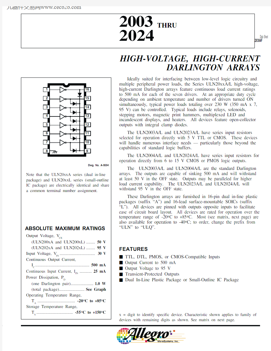
2003 THRU 2024
HIGH-VOLTAGE,HIGH-CURRENT DARLINGTON ARRAYS
https://www.360docs.net/doc/8e7530625.html,
Test Applicable
Limits Characteristic Symbol Fig.Devices
Test Conditions Min.Typ.Max.Units Output Leakage Current
I CEX
1AA ll
V CE = 50 V, T A = 25°C —< 150μA V CE = 50 V, T A = 70°C
—< 1100μA 1B
ULN2004A/L
V CE = 50 V, T A = 70°C, V IN = 1.0 V
—
< 5500μA Collector-Emitter
V CE(SAT)
2
A ll
I C = 100 mA, I B = 250 μA—0.9 1.1V Saturation Voltage
l C = 200 mA, I B = 350 μA— 1.1 1.3V I C = 350 mA, I B = 500 μA— 1.3 1.6V Input Current
I IN(ON)
3ULN2003A/L
V IN = 3.85 V —0.93 1.35mA ULN2004A/L
V IN = 5.0 V —0.350.5mA V IN = 12 V
— 1.0 1.45mA I IN(OFF)
4
A ll l C = 500 μA, T A = 70°C
50
65—μA Input Voltage
V IN(ON)
5ULN2003A/L
V CE = 2.0 V, l C = 200 mA—— 2.4V V CE = 2.0 V, I C = 250 mA—— 2.7V V CE = 2.0 V, l C = 300 mA—
— 3.0V ULN2004A/L
V CE = 2.0 V, l C = 125 mA—— 5.0V V CE = 2.0 V, l C = 200 mA—— 6.0V V CE = 2.0 V, I C = 275 mA——7.0V V CE = 2.0 V, l C = 350 mA—
—8.0V Input Capacitance C IN —A ll —1525pF Turn-On Delay t PLH 8All 0.5 E IN to 0.5 E OUT —0.25 1.0μs Turn-Off Delay t PHL 8All 0.5 E IN to 0.5 E OUT —0.25 1.0μs Clamp Diode
I R 6A ll V R = 50 V, T A = 25°C ——50μA Leakage Current V R = 50 V, T A = 70°C
—
—100μA Clamp Diode V F
7
A
ll
I F = 350 mA—
1.7
2.0
V
Forward Voltage
Complete part number includes suffix to identify package style: A = DIP, L = SOIC.
Types ULN2003A, ULN2003L, ULN2004A, and ULN2004L ELECTRICAL CHARACTERISTICS at +25°C (unless otherwise noted).
2003 THRU 2024HIGH-VOLTAGE,HIGH-CURRENT
DARLINGTON ARRAYS
115 Northeast Cutoff, Box 15036
Worcester, Massachusetts 01615-0036 (508) 853-5000
Test Applicable Limits
Characteristic Symbol Fig.Devices
Test Conditions
Min.Typ.Max.Units Output Leakage Current
I CEX
1AA ll V CE = 95 V, T A = 25°C
—< 150μA V CE = 95 V, T A = 70°C
—< 1100μA 1B
ULN2024A/L
V CE = 95 V, T A = 70°C, V IN = 1.0 V
—
< 5500μA Collector-Emitter
V CE(SAT)
2
A ll
I C = 100 mA, I B = 250 μA—0.9 1.1V Saturation Voltage
l C = 200 mA, I B = 350 μA— 1.1 1.3V I C = 350 mA, I B = 500 μA— 1.3 1.6V Input Current
I IN(ON)
3ULN2023A/L
V IN = 3.85 V —0.93 1.35mA ULN2024A/L
V IN = 5.0 V —0.350.5mA V IN = 12 V
— 1.0 1.45mA I IN(OFF)
4A ll l C = 500 μA, T A = 70°C
50
65—μA Input Voltage
V IN(ON)
5ULN2023A/L
V CE = 2.0 V, l C = 200 mA—— 2.4V V CE = 2.0 V, I C = 250 mA—— 2.7V V CE = 2.0 V, l C = 300 mA—
— 3.0V ULN2024A/L
V CE = 2.0 V, l C = 125 mA—— 5.0V V CE = 2.0 V, l C = 200 mA—— 6.0V V CE = 2.0 V, I C = 275 mA——7.0V V CE = 2.0 V, l C = 350 mA—
—8.0V Input Capacitance C IN —A ll —1525pF Turn-On Delay t PLH 8All 0.5 E IN to 0.5 E OUT —0.25 1.0μs Turn-Off Delay t PHL 8All 0.5 E IN to 0.5 E OUT —0.25 1.0μs Clamp Diode
I R 6A ll V R = 95 V, T A = 25°C ——50μA Leakage Current V R = 95 V, T A = 70°C
—
—100μA Clamp Diode V F
7
A ll
I F = 350 mA—
1.7
2.0
V
Forward Voltage
Complete part number includes suffix to identify package style: A = DIP, L = SOIC.
Types ULN2023A, ULN2023L, ULN2024A, and ULN2024L
ELECTRICAL CHARACTERISTICS at +25°C (unless otherwise noted).
115 Northeast Cutoff, Box 15036
Worcester, Massachusetts 01615-0036 (508) 853-5000
Dwg. GP-067
COLLECTOR-EMITTER SATURATION VOLTAGE Dwg. GP-068
INPUT CURRENT IN μA
2003 THRU 2024HIGH-VOLTAGE,HIGH-CURRENT
DARLINGTON ARRAYS
115 Northeast Cutoff, Box 15036
Worcester, Massachusetts 01615-0036 (508) 853-5000
PACKAGE DESIGNATOR “A”
Dimensions in Inches (controlling dimensions)
Dimension in Millimeters (for reference only)
NOTES:1.
Leads 1, 8, 9, and 16 may be half leads at vendor’s option.2.Lead thickness is measured at seating plane or below.3.Lead spacing tolerance is non-cumulative.
4.Exact body and lead configuration at vendor’s option within limits shown.
Dwg. MA-001-16A mm
18
Dwg. MA-001-16A in
18
2003 THRU 2024
HIGH-VOLTAGE,HIGH-CURRENT DARLINGTON ARRAYS
https://www.360docs.net/doc/8e7530625.html,
PACKAGE DESIGNATOR “L”
Dimensions in Inches (for reference only)
Dimension in Millimeters (controlling dimensions)
NOTES:1.Lead spacing tolerance is non-cumulative.
2.Exact body and lead configuration at vendor’s option within limits shown.
Dwg. MA-007-16A mm
16
9
Dwg. MA-007-16 in
16
9
2003 THRU 2024HIGH-VOLTAGE,HIGH-CURRENT
DARLINGTON ARRAYS
115 Northeast Cutoff, Box 15036
Worcester, Massachusetts 01615-0036 (508) 853-5000
The products described here are manufactured under one or more U.S. patents or U.S. patents pending.
Allegro MicroSystems, Inc. reserves the right to make, from time to time, such departures from the detail specifications as may be required to permit improvements in the performance, reliability, or
manufacturability of its products. Before placing an order, the user is cautioned to verify that the information being relied upon is current.Allegro products are not authorized for use as critical components in life-support devices or systems without express written approval.The information included herein is believed to be accurate and reliable. However, Allegro MicroSystems, Inc. assumes no responsi-bility for its use; nor for any infringement of patents or other rights of third parties which may result from its use.