RO3101E-1;中文规格书,Datasheet资料
CAUTION: Electrostatic Sensitive Device. Observe precautions for handling.Notes:
Electrical Characteristics Characteristic
Sym
Notes
Minimum
Typical
Maximum
Units
Center Frequency (+25 °C)Absolute Frequency f C 2,3,4,5433.870
433.970MHz Tolerance from 433.920 MHz
Δf C ±50
kHz Insertion Loss IL 2,5,6 1.4 2.2
dB
Quality Factor Unloaded Q Q U 5,6,7
828050 Ω Loaded Q Q L 1228
Temperature Stability
Turnover Temperature T O 6,7,810
2535°C Turnover Frequency
f O f C Frequency Temperature Coefficient
FTC 0.032ppm/°C 2Frequency Aging
Absolute Value during the First Year |f A |
1≤10ppm/yr DC Insulation Resistance between Any Two Terminals
5
1.0
M ΩRF Equivalent RLC Model
Motional Resistance R M 5, 7, 9
17.5ΩMotional Inductance L M 53.5μH Motional Capacitance C M 2.5fF Shunt Static Capacitance
C O 5, 6, 9 2.5pF Test Fixture Shunt Inductance
L TEST
2, 753.2
nH
Lid Symbolization (in addition to Lot and/or Date Codes)
750 // YWWS
Standard Reel Quantity Reel Size 7 Inch 10
500 Pieces/Reel Reel Size 13 Inch
3000 Pieces/Reel
?Ideal for European 433.92MHz Transmitters ?Very Low Series Resistance ?Quartz Stability
?
Complies with Directive 2002/95/EC (RoHS)
The RO3101E-1 is a true one-port, surface-acoustic-wave (SAW) resonator in a surface-mount, ceramic case. It provides reliable, fundamental-mode, quartz frequency stabilization of fixed-frequency transmitters operating at 433.92MHz. This SAW is designed specifically for remote-control and wireless security transmitters operating in Europe under ETSI I-ETS 300 220 and in Germany under FTZ 17 TR 2100.
Absolute Maximum Ratings Rating
Value
Units
Input Power Level 0dBm DC voltage
12VDC Storage Temperature Range -40 to +125°C Operating Temperature Range
-40 to +105
°C Soldering Temperature (10 seconds / 5 cycles max.)
260
°C
433.92 MHz
SAW Resonator
RO3101E-1
1.
Frequency aging is the change in f C with time and is specified at +65°C or less. Aging may exceed the specification for prolonged temperatures
above +65°C. Typically, aging is greatest the first year after manufacture, decreasing in subsequent years.
2.
The center frequency, f C , is measured at the minimum insertion loss point, IL MIN , with the resonator in the 50Ω test system (VSWR ≤ 1.2:1). The shunt inductance, L TEST , is tuned for parallel resonance with C O at f C . Typically, f OSCILLATOR or f TRANSMITTER
is approximately equal to the resonator f C .
3.One or more of the following United States patents apply: 4,454,488 and 4,616,197.
4.Typically, equipment utilizing this device requires emissions testing and government approval, which is the responsibility of the equipment manufacturer.
5.Unless noted otherwise, case temperature T C =+25°C±2°C.
6.
The design, manufacturing process, and specifications of this device are
subject to change without notice.
7.Derived mathematically from one or more of the following directly measured parameters: f C , IL, 3dB bandwidth, f C versus T C , and C O .8.
Turnover temperature, T O , is the temperature of maximum (or turnover) frequency, f O . The nominal frequency at any case temperature, T C , may be calculated from: f =f O [1-FTC (T O -T C )2]. Typically oscillator T O is approximately equal to the specified resonator T O .
9.
This equivalent RLC model approximates resonator performance near the resonant frequency and is provided for reference only. The capacitance C O is the static (nonmotional) capacitance between the two terminals measured at low frequency (10MHz) with a capacitance meter. The
measurement includes parasitic capacitance with "NC” pads unconnected. Case parasitic capacitance is approximately 0.05pF. Transducer parallel capacitance can by calculated as: C P ≈C O -0.05pF.10.
Tape and Reel Standard Per ANSI / EIA 481.
Pb
Equivalent LC Model
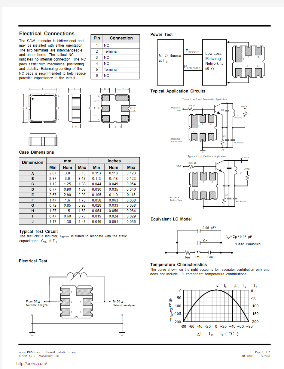
Temperature Characteristics
The curve shown on the right accounts for resonator contribution only and does not include LC component temperature contributions.
Pin
Connection
1NC
2Terminal 3NC 4NC 5Terminal 6
NC
Power Test
Electrical Connections
The SAW resonator is bidirectional and may be installed with either orientation. The two terminals are interchangeable and unnumbered. The callout NC
indicates no internal connection. The NC pads assist with mechanical positioning and stability. External grounding of the NC pads is recommended to help reduce parasitic capacitance in the circuit.
Typical Test Circuit
The test circuit inductor, L TEST , is tuned to resonate with the static capacitance, C O , at F C .
Electrical Test
Typical Application Circuits
Case Dimensions Dimension
mm Inches
Min
Nom
Max
Min
Nom
Max
A 2.87 3.0 3.130.1130.1180.123
B 2.87 3.0 3.130.1130.1180.123
C 1.12 1.25 1.380.0440.0490.054
D 0.770.90 1.030.0300.0350.040
E 2.67 2.80 2.930.1050.1100.115
F 1.47 1.6 1.730.0580.0630.068
G 0.720.850.980.0280.0330.038
H 1.37 1.5 1.630.0540.0590.064
I 0.470.600.730.0190.0240.029J
1.17
1.30
1.43
0.046
0.051
0.056
分销商库存信息: RFM
RO3101E-1