Fisher 蝶型调节阀样本

?Fisher Controls International, Inc. 1997; All Rights Reserved
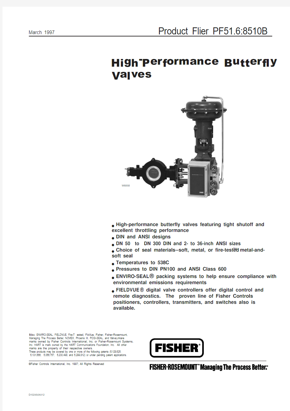
Product Flier PF51.6:8510B
March 1997
High-Performance Butterfly Valves
edisc, ENVIRO-SEAL, FIELDVUE, Fire-T ested, FloVue, Fisher, Fisher-Rosemount,Managing The Process Better, NOVEX, Phoenix III, POSI-SEAL, and ValveLinkare marks owned by Fisher Controls International, Inc. or Fisher-Rosemount Systems,Inc. HART is mark owned by the HART Communications Foundation, Inc. All other marks are the property of their respective owners.
These products may be covered by one or more of the following patents (5,129,625;
5,131,666; 5,056,757; 5,230,498; and 5,299,812) or under pending patent applications.l High-performance butterfly valves featuring tight shutoff and
excellent throttling performance l DIN and ANSI designs
l DN 50 to DN 300 DIN and 2- to 36-inch ANSI sizes
l Choice of seal materials--soft, metal, or fire-tested ? metal-and-soft seal
l Temperatures to 538°C
l Pressures to DIN PN100 and ANSI Class 600
l ENVIRO-SEAL ? packing systems to help ensure compliance with
environmental emissions requirements
l FIELDVUE ? digital valve controllers offer digital control and
remote diagnostics. The proven line of Fisher Controls positioners, controllers, transmitters, and switches also is available.
D102454X412
W6858
2
Product Flier PF51.6:8510B
High-Performance Valves for Excellent Flow Control and Shutoff
Accurate Flow Control...The
valves have a splined-and-clamped connections to positioning actuators for accurate throttling or on-off control. The valves are capable of throttling through 90 degrees of disc rotation with an approximately linear or modified equal percentage (Type 8532) characteristic.The splined-and-clamped valve-actuator connection reduces lost motion and deadband.
The valves and actuators can be reversed from push-down-to-close to push-down-to-open in the field without additional parts.
Excellent Shutoff...The soft and
metal seals are pressure assisted for excellent shutoff.
Type 8510B edisc ? Valves ... for DIN or ANSI applications. The
valves feature DIN dimensions and compatibility. The valve shaft is a through, balanced shaft.Also, the eccentric disc path reduces seating torque
requirements and seat wear.Type 8560 Valves...For ANSI applications. The Type 8560 valve is available with a Fire-Tested?seal that can meet fire-safe standards.
Type 8532 Valves...This valve
shares many features with the Type 8560 valve and is available in larger sizes.
Type 8510 edisc ? Valves...The Type 8510 valve is an ANSI design version of the Type 8510B valve in 30- and 36-inch sizes. The 36-inch size is compatible with DIN flanges.
W3542-2
Typical Type 8510B and 8510 Construction
A6936
Pressure-Assisted Seals (Vertical Arrows Indicate Disc Position with no Pressure)
DISC POSITION WITH NO PRESSURE
DIREC-TION OF PRES-SURE
DIREC-TION OF PRES-SURE
3
Product Flier PF51.6:8510B
High-Performance Valves (Continued)
Protection Against Process Fluid Emissions...Optional ENVIRO-SEAL ? packing systems provide a superior shaft seal to prevent the loss of valuable or hazardous process fluids. This live-loaded system provides longer packing life and reliability.
Materials for Sour
Service...Fisher Controls offers materials and manufacturing procedures for compliance with NACE (National Association of Corrosion Engineers) standard MR0175.
POSI-SEAL? Types A31A and A41...For less stringent throttling applications and for on-off
applications requiring the same excellent shutoff capabilities as the Type 8560 and 8532. The Type A31A and A41 valves connect to a rack-and-pinion piston actuator,manual handwheel actuator, or handlever.
H.D. Baumann 21000 Series ...For applications that require an
elastomer-lined valve in 2- through 6-inch sizes.
Other Butterfly Valves
ENVIRO-SEAL ? Packing System (Single PTFE V-Ring)
W5806-1
Type 8560 Valve with Actuator
W6213/IL
4
Product Flier PF51.6:8510B
Actuators
Type 1061 Actuator
Type 1052 Actuator Type 1051 and 1052Pneumatic Diaphgragm Actuators...Rugged, heavy-duty spring-return actuators.These actuators are available with a variety of instrument accessories, handwheels,adjustable travel stops, and a maintenance lock-out device.Type 1061 Pneumatic Piston Actuator...Heavy-duty piston
The High-Performance Valve Family (Continued)The Actuators are Available in any
of Four Styles and Positions (Above
the Pipeline as Shown Here,
Below, or Parallel with the Pipeline)
actuator available with a variety of instrument accessories, handwheels and piston bypass valves, and a maintenance lockout device.Type 1077 Manual Handwheel Actuator...Available for manual-only operation.
Actuator Accessories
FIELDVUE ? Digital Valve
Controller...Available mounted on
Type 1051 and 1052 actuators.Positioners and
Transducers...Pneumatic positioners and electro-pneumatic positioners and transducers can be provided with these actuators.
Position Transmitters, Solenoid Valves, Volume Boosters, and Limit Switches...Also available.
RIGHT-HAND MOUNTING
LEFT-HAND MOUNTING
STYLE D
STYLE C
STYLE B STYLE A A1579-4/IL
Actuators are Field-Reversible from Push-Down-to Close (PDTC) to Push-Down-to Open (PDTO)
J407T13
MOUNT-ING
ACTION
STYLE
Right hand PDTC PDTO
B A Left hand
PDTC PDTO C D
W5978
Product Flier PF51.6:8510B Selecting High-Performance Products
Only a few of the more commonly selected product materials, sizes,
options, and accessories are covered in this flier.
Contact your nearest sales office or sales representative (refer to the back
cover) for assistance in selecting and sizing these products. More detailed
specifications are available on request.
Selecting Valve Components
Valve Type Selection (6)
Valve Body Information (6)
Primary Valve Component Materials (7)
Temperature Capabilities of Selected Combinations (8)
Inlet Pressure Ratings for M35-1 (Monel) Valves (8)
Selecting an Actuator
Type 1051 and 1052 Pneumatic Diaphragm Actuators (9)
Type 1061 Pneumatic Piston Actuator (10)
Selecting Accessories
FIELDVUE? Digital Valve Controller (11)
3610J Series Valve Positioners (12)
Other Accessories (13)
Reference Information
Flow Coefficients (14)
Conversions for Other Sizing Equations (14)
Typical Actuator-Valve Size Combinations (15)
Actuator Size Selection (Shutoff Pressure Drop) (16)
Dimensions (17)
Typical Weights (18)
Ordering Information (19)
Sales Offices and Sales Representatives (20)
5
6
Product Flier PF51.6:8510B
Valve Body Information
J407T02
Valve Type Selection
J407T01
APPLICATION
SHUTOFF
CLASSIFICATION PER IEC 534-4AND FCI/ANSI 70-2-1991
SIZES,DN OR INCHES RATINGS, DIN PN OR ANSI
CLASS VALVE
TYPE NUMBER
NOTES
Service Valve Body Tempera-ture
Seal
DIN to DN 300 &
to PN100 rating
Wafer-style steel or stainless steel body
to 232C PTFE
See notes for
standard;
Class VI is
optional
DN 50DN 80DN 100DN 150DN 200DN 250DN 30010, 25, 40, 63, & 10010, 25, 40, 63, & 10010, 25, 40, 63, & 10010, 25, 40, 63, & 10010, 25, 40, 63, & 10010 & 16 or 25 & 40
10 & 16 or 25 & 40
8510B
Standard shutoff for Type 8510B and 8510with PTFE seal is 2mL/minute of air per inch of valve size at a pressure drop of 3.4bar.
Refer to pages 7 and 8 for more detailed information about materials and temperatures.
The 30- and 36-inch sizes are compatible with DIN PN10 and PN 16 flanges.
to 538°C S31600 (316stainless steel)1/10 of Class IV ANSI to 12-inch &
to Class 600
Wafer-style steel,
stainless steel,CN7M (alloy 20)
or M35-1 (Monel)
body
to 232°C PTFE
See notes for
standard;
Class VI is optional 2
34681012
150/300/600150/300/600150/300/600150/300/600150/300/600150 or 300150 or 300to 538°C S31600 1/10 of Class IV
ANSI to 24-inch &
to Class 300Wafer-style or
single-flange
steel or stainless steel body to 204°C Soft VI
34
6
810121416
18
20
24
150 or 3008560 (to 12-inch)or 8532(greater than 12-inch)
to 538°C NOVEX seal 1/10 of Class IV is standard: Class V is optional to 232°C Phoenix III metal/soft
VI Phoenix III Fire-Tested seal VI ANSI 30- & 36-inch & Class 150rating Wafer-style steel
or stainless steel
body
to 232°C PTFE See notes for
standard; Class V is optional 3036150 (per MSS SP-44)
8510
to 538°C S316001/10 of IV
Sizes
Type
Valve Body Materials
Face-to-Face Dimensions
Mating Flange Compatiblity
DIN or ANSI
DN 50through DN 300 & 2through 12inches
8510B
DIN 1.0619 steel (17245) DIN 1.4581stainless steel, WCC steel, CF3M (316L stainless steel), M35-1 (Monel), & CN7M
(alloy 20)DIN: 3202 Part 3/K2
ANSI: API 609 for all
Class 150 valves & for 3-through 6-inch Class 300Raised-face flanges; all sizes compatible
with with schedule 80 and lighter welding-neck and slip-on flanges
ANSI
3 through 2
4 inches 8560 &8532Steel, CF8M (316 stainless steel), & CG8M
(317 stainless steel)API 609 & MSS SP68Raised-face flanges; all Type 8560 sizes compatible with schedule 80 and lighter
welding-neck and slip-on flanges 30 & 36inches
8510
WCB steel, CF8M (316 stainless steel), &
CN7M (alloy 20)
30-inch: 191 mm 36-inch: 222 mm
Class 150 raised-face flanges (MSS SP44); compatible with schedule 40 and lighter welding-neck and slip-on flanges
7
Product Flier PF51.6:8510B
Primary Valve Component Materials
J407T03
Phoenix III Seal
A6937
Single-Flange Valve
W6361
RESILIENT INSERT
BACKUP O-RING
DISC
SEAL RING
GASKET
RETAINING
RING
VALVE BODY
Part
DIN or ANSI (Type 8510B: DN 50
through DN 300)
ANSI (Type 8560: 3- through
12 inch)
ANSI (Type 8532: 14-through 24-inch)
ANSI (Type 8510: 30 &
36-inch)
Notes
Disc
n WCC steel, n CF3M (316L stainless steel, n 35-1 (Monel) or n CN7M (alloy 20)
n CF3M or n CG8M (317stainless steel)n Steel or n CF8M (316stainless steel)
n WCB steel, n CF3M (316 stainless steel), n M35-1 (Monel) or n CN7M (alloy 20)
? PEEK is poly-ether-ether ketone
? UHMWPE is ultra high-molecular weight polyethylene ? Contact your sales office or sales
representative for more
information on ENVIRO-SEAL packing
Seal
n PTFE composition (filled PTFE for CF3M valves) or n S31600(316 stainless steel)
n PTFE or n UHMWPE with backup ring of:
? nitrile ? neoprene, ?EPR, ?fluoroelastomer, or ? PTFE n NOVEX seal S31600(standard for Class 150) or Nitronic 60 (standard for Class 300)n S31600/PTFE Phoenix III or Phoenix III fire-tested seal with backup ring of:
? nitrile ? neoprene, ? EPR, or ? PTFE
n PTFE, n UHMWPE,
n NOVEX seal S31600
(standard for Class 150) or Nitronic 60 (standard for Class
300), n Phoenix III
metal/fluoreoelastomer, or
n Phoenix III
metal/fluoreoelastomer fire-tested seal n PTFE composition or
n S31600
Bear-ings
n PTFE/Composition with S31603jacket, n S44004 (440C stainless steel) n alloy 6 with or without silver plating, n Filled PTFE with N04400 (Monel) or N08020 (alloy 20) jacket
n PEEK/PTFE lined or n metal
(NOVEX or Phoenix II seals
only)
n PEEK, n S31600, n alloy 6, or n bronze n PTFE/Composition with S31603 jacket, n S44004,
n alloy 6B with or without
silver plating, or n Filled
PTFE with N04400, or N08020 jacket
Valve shaft
n S17400 (17-4PH stainless steel),n S20910 (Nitronic 50 stainless steel), n N05500 (Monel), n N10276 (alloy 276), or n N08020(alloy 20)
n S17400 or n S20910n S17400 or n S20910
n S17400, n S20910), n N05500, or n N08020Packing n PTFE V-ring, n PTFE-composition (both with one
conductive ring), n graphite ribbon
rings, or n ENVIRO-SEAL packing
n PTFE V-ring, n graphite, or
n
ENVIRO-SEAL packing n PTFE V-ring, n graphite, or n
ENVIRO-SEAL packing n PTFE V-ring, n PTFE-composition (both with one conductive ring),
n graphite ribbon rings, or n ENVIRO-SEAL packing (30-Iinch size only)
8
Product Flier PF51.6:8510B
J407T04
Temperature Capabilities of Selected Combinations
Only selected combinations are shown here. Consult the previous table and your sales office or sales representative for other combinations. For simplicity, only general material names are given here; refer to the previous tables for more complete descriptions. For Type 8510 and 8510B valves with PTFE bearings, limit maximum temperature to 207°C with water or steam.
Inlet Pressure Ratings for M35-1 (Monel) Valve Bodies,
Bar
J407T15
Temperature, °C
150
300
600
Note
-29 to 38
93149204232
15.813.813.112.712.341.336.534.133.133.082.772.768.265.865.7
M35-1 is not listed in ASME/ANSI B16.34. The designations 150,300, and 600 indicate relative
pressure-retaining capabilities and are not ANSI pressure-temperature rating classes.
Valve Body
Disc
Shaft
Seal
Bearings
Packing
Temperature,
°C
Note
TYPE 8510B--DN 50 to DN 300 or 3- to 12 INCH & 8510-- 30- & 36-INCH
For DIN valve bodiess, the minimum
temperature is
normally limited to -10°C. Contact your sales office or sales representative if lower temperatures are required and for pressure and
temperature limits with ENVIRO-SEAL packing..
Steel Steel S17400PTFE S31600PTFE-composition S44004
PTFE Graphite -29 to 232-29 to 427Stainless steel
Stainless steel S17400 or N20910PTFE PTFE-composition
PTFE -40 to 232Chrome-plated stainless steel
S17400N20910S31600S31600Alloy 6Alloy 6
Graphite Graphite -40 to 232-46 to 538TYPE 8510B--DN 50 to DN 300 or 3- to 12 INCH
M35-1M35-1N05500PTFE PTFE-composition PTFE Graphite -40 to 232-46 to 232CN7M
CN7M
N08020
PTFE
PTFE-composition
PTFE Graphite -40 to 149-46 to 149TYPE 8560--3- to 12-INCH
Steel Stainless steel S17400 or N20910
PTFE
NOVEX seal
Phoenix III seal
PEEK/PTFE Metal PEEK/PTFE or metal PTFE Graphite PTFE -29 to 232-29 to 427-29 to 232Stainless steel
Stainless steel
S17400
PTFE
NOVEX seal
Phoenix III seal
PEEK/PTFE Metal PEEK/PTFE PTFE Graphite PTFE -46 to 232-29 to 427 -40 to 232N20910
PTFE
NOVEX seal
Phoenix III seal
PEEK/PTFE Metal PEEK/PTFE PTFE Graphite PTFE -46 to 232-29 to 538-40 to 232TYPE 8532--14- to 24-NCH Steel Steel or stainless
steel S17400 or N20910
PTFE with PTFE backup ring NOVEX seal Phoenix III with EPR backup ring PEEK/PTFE
S31600
PEEK/PTFE
PTFE Graphite PTFE -29 to 204-29 to 538-29 to 204Stainless steel
Stainless steel
S17400 or N20910
N20910
S17400 or N20910
PTFE with PTFE backup ring
NOVEX seal
Phoenix III with EPR backup ring
PEEK/PTFE S31600PEEK/PTFE PTFE Graphite PTFE
-29 to 232-29 to 538-29 to 232
9
Product Flier PF51.6:8510B
Type 1051 and 1052 Actuators
H419T40
Type 1051 and 1052 pneumatic diaphragm rotary actuators are spring-return actuators that provide reliable operation for the valves in this flier.
The Type 1051 actuator is suitable for on-off operation or for throttling operation when equipped with a valve controller or positioner. The Type 1052 actuator is suitable for on-off or throttling with or without a controller or positioner.
These actuators feature single-joint linkage with splined-and-clamped levers for minimum lost motion and high control accuracy.
The actuator-valve linkage is
completely enclosed for safety, yet the packing adjustment is
accessible without removing any parts.
Specifications...Refer to the table below and the actuator selection tables.
Options...n Top-mounted handwheel, n Type 1078
declutchable handwheel actuator,n Adjustable up- and down-travel stops, n Actuator locking
mechanism that keeps the actuator in a locked position during
maintenance, and n Pipe-away vent for remote venting of the actuator housing.
Accessories...n Pneumatic and electro-pneumatic valve postioners,n FIELDVUE ? digital valve controller, and n Limit and proximity switches.
Size 33 Actuator
Typical Type 1052 Actuator
W3813-1
W4742-1
ACTUATOR SIZE NOMINAL OPERATING PRESSURE
RANGES
MAXIMUM CASING
PRESSURE, BAR MAXIMUM VALVE BREAKOUT TORQUE, N?m AMBIENT
TEMPERATURES, °C
MATERIALS
Type 1051
Type 1052
Bar
Psig
Type 1051
Type 1052
Type 1051
Type 1052
- - -20n 0 to 1.2, n 0 to 2.3, and n 0 to 2.8n 0 to 11, n 0 to 33,
and n 0 to 40
- - - 4.1- - -42Nitrile: -40 to 82Silicone: -50 to 149
Diaphragm: Nitrile (standard) or silicone
elastomers
O-rings (for optional handwheel): Nitrile or
EPDM
Housing: Cast iron (standard) or steel Other Major Metal Parts: Aluminum, steel,
or cast iron
3333n 0 to 1.2, n 0 to 2.3, n 0 to 2.8, and n 0 to 3.8n 0 to 18, n 0 to 33,n 0 to 40, and n 0
to 55 4.5851324040 5.23227306060n 0 to 1.2, n 0 to
2.3, and n 0 to 2.8n 0 to 11, n 0 to 33,
and n 0 to 40 3.4626
6460- - -70
n 0 to 2.3, n 0 to 2.8, and n 0 to 3.8
n 0 to 33, n 0 to 40,
and n 0 to 55
- - -
4.5- - -
1370
Product Flier PF51.6:8510B
Type 1061 Actuators
Type 1061 pneumatic rotary actuators are double-acting piston actuators that provide reliable operation for the valves in this flier. The Type 1061 can be used with a two-position control signal for on-off operation or with a valve controller or positioner for throttling operation.
These actuators feature single-joint linkage with splined-and-clamped levers for minimum lost motion and high control accuracy.
The actuator-valve linkage is completely enclosed for safety, yet the packing adjustment is accessible without removing any parts.
Specifications...Refer to the table below and the actuator selection tables.
Options... n Type 1078 declutchable handwheel actuator with cylinder bypass valve, n Adjustable up- and down-travel stops, n Actuator locking mechanism that keeps the actuator in a locked position during maintenance, and n Pipe-away vent for remote venting of the actuator housing. Accessories...n Pneumatic and electro-pneumatic valve postioners and n Limit and proximity switches.
H419T41
W3827-1
ACTUATOR
SIZE CYLINDER OPERATING PRESSURE, BAR MAXIMUM VALVE
BREAKOUT TORQUE,
N?m
AMBIENT
TEMPERATURES, °C
MATERIALS Minimum
Recommended
Maximum Allowable
30
Without positioner: 1.4
With positioner: 0.35
bar above actuator
requirement 6.9282
-34 to 82
(to -50 with optional
materials)
Cylinder and flange: Aluminum
Piston: Aluminum or nylon-
coated aluminum
O-rings: Nitrile
Mounting yoke bushing: PTFE
and steel
Sliding seal: Brass
Other parts: Iron, aluminum,
and stainless steel
4010.3847
60 6.91130
68 5.91540
8010.35080 10010.36290
10
11
Product Flier PF51.6:8510B
Type DVC5020 Digital Valve Controller
W6161
FIELDVUE digital valve controllers are communicating,
microprocessor-based controllers that convert a current signal to a pressure signal to operate the actuator. Through the HART ?communications protocol, the controller gives easy access to actuator-valve information that is critical to process operation.The Type DVC5020 controller is available to mount on Type 1051and 1052 actuators.
ValveLink? Software...ValveLink software allows easy access to the information available from the FloVue ? system. The software provides diagnostic information such as dynamic error band and Type DVC5020 Controller on a Valve and Actuator with Model 275HART Communicator
FIELDVUE Valve Controller Physical Specifications
SUPPLY PRESSURE, BAR OUTPUT SIGNAL
STEADY-STATE
AIR
CONSUMPTION,
Nm 3/h
TEMPERATURE
LIMITS
WEIGHT
HOUSING
Minimum and Recommended
Maximum
As needed by actuator
6.5
Up to 95%of supply pressure
Less than 0.3 at 1.4bar supply pressure
-40 to 80°C 2.7
kg
IP 65 per IEC 529classification
H419T45
H410T06
H419T49
FIELDVUE Controller Electrical Specifications
ELECTRICAL INPUT
DIGITAL
COMMUNICATION INPUT SIGNAL
Analog Input
Signal
Voltage
Minimum Control Current Minimum Current
without
Microprocessor
Restart
Maximum Current
Polarity Protection
n 4 to 20, n 4
to 12 or n or 12
to 20 mA dc
(user adjustable)
12 Vdc minimum
and 30 Vdc
maximum
4.0 mA 3.5 mA 100 mA
-30 Vdc minimum without damage
HART 1200 baud frequency shift
keyed
FIELDVUE Digital Controller Certifications
INTRINSIC SAFETY INTRINSIC SAFETY OR NON-INCENDIVE
FLAMEPROOF
DIVISION 2
EXPLOSION-PROOF LCIE
CSA (1) or FM (1)
SAA
CENELEC
SAA
CSA
FM
CSA or FM
EEx ia IIC T5
Class I, Division
1, Groups (1) A,
B, C, D
T5 (T amb 80°C)
Ex n IIC T5, T6Ex ia IIC T4, T5, T6EEx d IIB + H 2T5 (T amb 80°C)EEx d IIB + H 2T6 (T amb 80°C)
Class I Division 2,Groups A, B, C, D Class II, Division 2,Groups E, F, G Class I Division 2,Groups A, B, C, D Class II, Division 2, Groups F, G Class I Division 1,Groups B, C, D Class II, Division 1,Groups E, F, G
1. Contact your nearest sales office or sales representative for the appropriate FM entity ratings and CSA parametric ratings for each group.
12
Product Flier PF51.6:8510B
3610J Series Valve Positioners
The 3610J Series pneumatic and 3620J Series electro-pneumatic valve positioners can be used with Type 1051, 1052, or 1061actuators for accurate valve
positioning in throttling applications.The positioners provide accurate,fast response and can withstand the vibrations in most plants.The positioners are easily
reversible for direct or reverse
action without additional parts.The 3610J positioners are single acting for Type 1051 and 1052actuators, and the 3610JP
positioners are double acting for Type 1061 actuators.
Options...n Supply pressure gauge, n Tire valves for clip-on gauges, and n Integrally mounted bypass valve for single-acting actuators
H419T42
H419T43
H419T44
3610J and 3620J Positioner Specifications
Type
Input Signal
Supply Pressure
Operative Temperature
WEIGHT
Connections
3610J and 3610JP
n 0.2 to 1.0 or n 0.4 to 2.0 bar n 3 to 15 or
n 6 to 30 psig
0.3 bar above the actuator
requirement up to 10.3 bar
maximum
-40 to 80°C
2.5
kg Pressure and Vent
Connections: 1/4-inch NPT
Type 3620J and JP
Conduit:1/2 NPT
3620J and
3620JP
4 to 20 mA constant current with
30 Vdc maximum compliance
voltage; equivalent circuit is 120ohms shunted by three 5.6 V zener
diodes 0.3 bar above the actuator requirement up to 10.3 bar
maximum -40 to 80°C 3.6 kg
3610J and 3620J Series Capacities and Housing
Type
SUPPLY
PRESSURE, BAR
SUPPLY AIR DEMAND, Nm 3/h
Air Consumption, Nm 3/h
Housing (Types 3620J
and 3620JP)3610J and 3620J
1.413Type 3610J: 0.40 at 1.4 bar supply
Type 3620J: 0.49 at 1.4 bar supply
IP 54 per IEC 529
classification
(weatherproof), NEMA 3;vent should be on the side
or bottom for weatherproof
applications
2.4173610JP and 3620JP
5.237Type 3610JP: 0.64 at
6.9 bar supply
Type 3620JP: 0.93 at 6.9 bar supply
6.9
46
Type 3622 Electro-Pneumatic Converter Certifications
INTRINSIC SAFETY OR
NON-INCENDIVE INTRINSIC
SAFETY OR NON-INCENDIVE
FLAMEPROOF DIVISION 2
EXPLOSION-PROOF PTB
CSA (1)or FM (1)
SAA
LCIE
SAA
CSA
FM
CSA or FM
EEx ia IIC T6
Class I,Division 1,
Groups (1) A, B,
C, D T5
Ex ia IIC T4Ex n IIC T4
EEx d IICT6Ex d IIB T6
Class I Division 2, Groups A, B,C, D
Class II, Division
2, Groups E, F,
G
Class I Division
2, Groups A, B,
C, D Class II,Division 2,Groups F, G Class I, Division
1, Groups A, B,
C, D Class II Division
1, Groups E, F, G
1. Contact your nearest sales office or sales representative for the appropriate FM entity ratings and CSA parametric ratings for each group.
W4920-1*
Product Flier PF51.6:8510B Type 67AFR Filter-Regulator...The
Type 67AFR provides constantly
controlled supply pressure to
actuator accessories system. This
Type 67AFR Filter-Regulator Specifications
OUTLET PRESSURE SETTINGS MAXIMUM INLET
PRESSURE
(BODY RATING) ,
BAR
MAXIMUM
DIAPHRAGM
PRESSURE, BAR
TEMPERATURE
CAPABILITIES
CONNECTIONS
MAXIMUM FLOW
COEFFICIENT,
C
v
WEIGHT,
kg
Bar Psig
0.2 to 1.2 0.3 to 2.1 2.1 to 3.4 2.4 to 5.5
3 to 20
5 to 35
30 to 60
35 to 100
17.2
3.4 over outlet
setting or 7.6,
whichever is
greater
Nitrile diaphragm
and plug: -29 to
82°C
Fluoroelastomer
diaphragm and
plug: -18 to 149°C
Inlet and Outlet: 1/4-inch
NPT female
Vent: n 6.4 mm hole or
n 1/4-inch NPT female
0.280.7
H410T13
Type 646 or 846 Electro-Pneumatic Transducers...These transducers convert a standard 4 to 20 mA dc signal to a proportional pneumatic signal. Certifications are
n CE Mark to EMC directive (electromagnetic compatibility);
n Contact your nearest sales office or sales representative for intrinsic safe and flameproof ratings.
Type 2626 Volume Booster...The volume booster can be used in
conjunction with a postioner to increase actuator stroking speed.
Others...n High-pressure supply pressure regulators, n proximity switches, n microswitches,
n solenoid valves, and n signal volume boosters.
Contact your nearest sales office or sales representative for more information.
regulator features an internal filter and limited-capacity internal relief, allowing partial reduction of downstream pressure.
Other Accessories Type 3065 Limit Switch Box
The limit switch box can be installed on the Type 3024S actuator to hold proximity or microswitches, which can turn on an alarm or display device when a pre-set limit is reached. Additional microswitches are available.
The device has separate cams for open and closed positions, and adjustment of one cam does not affect the other.
Certifications...CE Mark to EMC
directive n EN 50081 and
n EN 50082
https://www.360docs.net/doc/8c16836100.html,plicated
adjustments are not required.
Standardized
Installation...Covered by IEC
534-6 (NAMUR). The box can be
supplied with a mounting kit.
W6682B
W5075
13
14
Product Flier PF51.6:8510B
Selected Flow Coefficients
J407T05
Conversions for Other Sizing Equations
Following are conversions for use with other common sizing equations.K V = (0.865) C V C 1 = 39.76(√X T )C g = C V C 1K m = F L 2
C S = 1/20 (C g ). C s is only applicable for inlet pressures up to 70 bar(a).
Line-to-Valve Size Ratios Greater than 1-to-1
Contact your nearest sales office or sales representative for information on deteriming the F P , the piping geometry factor.
VALVE SIZE
Valve Rotation, Degrees (Line Size Equals Valve Size)
10
30
60901030
60901030
6090
DIN
Inches
C
F
X
DIN or ANSI (Type 8510B Normal Flow--Seal Retainer Upstream)
DN 50DN 80DN 100DN 150DN 200DN 250DN 300234681012 2.256.2911.932.286.492.115119.948.282.522138247173258.91372225438891510226080.2247434921180035704880- - -- - -- - -- - -- - -- - -- - -.77.81.79.71.70.76.69.76.69.71.62.66.69.69.71.57.56.54.54.49.50.289.446.325.416.375.466.429.315.413.375.394.316.432.452.497.322.366.289.284.348.339.442.230.250.214.209.156.166
ANSI (Type 8532 Seal Side of Valve Facing Downstream)
Class 150
- - -- - -- - -- - -- - -141618202495129166208322995946122015202370398054206960873013 5406320860011 05013 85021 500
- - -.81.69.52.51.55.40.23
Class 300
- - -- - -- - -- - -- - -1416182024102136173214329747995127015702420306040705180641098806790905011 50014 25021950
- - -.81.69.52.51.55.33.23
ANSI (Type 8510 Normal Flow--Seal Retainer Upstream)
- - -- - -3036105015004550651015 40022 00035 00050 000
- - -.75.69.49
.284.284.413.416.255.258.160.160
15
Product Flier PF51.6:8510B
Typical Actuator-Valve Size Combinations
Shown are actuator size selections for two common valves. The tables illustrate the factors that must be considered when determining the pressure drop and actuator size for your application:
J407T08
VALVE TYPE
VALVE SIZE DIAPHRAGM TYPE 1051 &1052 SIZE PISTON
TYPE 1061 SIZE
DIN
Inches
8510B
DN 50DN 80DN 100DN 150DN 200, 250DN 30023468, 101220, 33, 4033, 4033, 40, 6040, 6040, 60, 7060, 703030
30,40, 60, 6830, 40, 60, 6830, 40, 60, 6840, 60, 68
Class 150 8560
- - -- - -- - -- - -- - -- - -3468101220, 33, 4033, 4033, 40, 6040, 6040, 60, 7060, 703030
30, 40, 60, 6830, 40, 60, 6830, 40, 60, 6840, 60, 68
Class 300 8560
- - -- - -- - -- - -- - -- - -34681012 33, 4033, 40, 6040, 6040, 60, 70 60, 7060, 7030
30, 40, 60, 6830, 40, 60, 6830, 40, 60, 6840, 60, 60
80Class 150 8532
- - -- - -- - -- - -14, 1618202440, 60, 7060, 7060, 70- - -40, 60, 6840, 60, 6840, 60, 68, 8040, 60, 68, 80
Class 300 8532
- - -- - -- - -14161860, 7060, 70- - -68, 8068, 8068, 80
8510
- - -
30, 36
- - -
80, 100
J407T14
Note
It is not implied that the selection shown is best for your application.For pressure drops
lower than those shown,a lower actuator pressure or smaller actuator might be satisfactory.
For pressure drops
higher than those shown,a higher operating pressure or larger
actuator will be required.
Contact your sales office or sales representative for other sizes and operating pressures.
With rotary valves, the highest pressure drop occurs when the valve is shut off. When the valve is open, pressure drop is normally much lower. However, pressure drop capabilities of a rotary valve also are lower when the valve is open. The allowable flowing pressure drop across a valve
depends on the valve construction,valve position, the type of flowing fluid (liquid or gas), and on the vapor pressure and critical pressure ratio of liquids.
Actuator Size Selection (Shutoff Pressure Drops)
Valve size
Inlet pressure and valve rating Valve component capabilities Fluid temperature Flow direction
Supply pressure available Desired action (air open or air to close)
16
Product Flier PF51.6:8510B
Actuator Size Selection (Shutoff Pressure Drops) (Continued)
J407T06
Type 8510B DIN or ANSI Valve (Steel) with PTFE Seal and PTFE Bearings (Forward Flow)
Type 8510B DIN or ANSI Valve (Steel) with S31600 Seal and PTFE Bearings (Forward Flow)
J407T07
Only allowable shutoff pressure drops are shown here. To
determine the allowable flowing pressure drop, provide your sales office or sales representative with the
application information shown on page 19.
Do not exceed any other limits
presented in this flier. Following is a brief reminder of some of those limits:Maximum Inlet Pressure and Temperature...Do not exceed the maximum rating of the valve (refer to the valve type selection table).
Materials Temperature Limits...Refer to the tables
showing temperature capabilities for valve materials, actuators, and accessories.
VALVE SIZE
Actuator
Size
Shutoff
Pressure Drop, Bar Pressure to Actuator
Notes
At 38°C At 232°C Bar Psig
Type 1052 Push-Down-to-Close (Air Closes)
DN 50DN 80DN 100DN 150234620
33
33
40
21.949.217.049.021.949.217.049.00 - 2.80 - 2.30 - 2.80 - 3.80 - 400 - 330 - 400- 55For higher pressure drops, larger actuators are available.
For lower pressure drops, lower operating pressures can be used Pressure drop at 232°C,if lower than the
pressure drop at 38°C, is based on the capabilities of the valve.
DN 200DN 250DN 3008101260
60
70
57.921.015.531.017.217.20 - 2.30 - 2.30 - 2.30- 330- 330 - 33Type 1061 Push-Down-to-Close or Open
DN 50DN 80DN 100DN 150234630
30
30
30
51.051.051.041.651.051.051.041.6 4.14.14.14.160606060DN 200DN 250DN 300
81012
40
60
40
31.017.214.431.017.214.4 6.94.15.51006080VALVE SIZE
Actuator
Size
Shutoff
Pressure Drop, Bar Pressure to Actuator
Notes
At 38°C At 232°C Bar Psig
Type 1052 Push-Down-to-Close (Air Closes)
DN 50DN 80DN 100DN 150234620
33
33
40
56.364.553.857.9 3.43.43.43.40 - 2.80 - 2.30 - 2.80 - 3.80 - 400 - 330 - 400 - 55For higher pressure drops, larger actuators are available.
For lower pressure drops, lower operating pressures can be used Pressure drop at 232°C is based on the
capabilities of the valve.
DN 200DN 250DN 3008101240
40
60
30.215.723.3 3.43.43.40 - 3.80 - 3.80 - 2.80 - 550 - 550 - 40Type 1061 Push-Down-to-Close or Open
DN 50DN 80DN 100DN 150234630
30
30
30
56.264.553.849.0 3.43.43.43.4 6.96.96.96.9100100100100DN 200DN 250DN 300
81012
30
30
40
20.910.121.1 3.43.43.4 6.96.96.9100100120
17
Product Flier PF51.6:8510B
Dimensions
J407T09
H419T24
Actuator Type
Actuator Size
C E
1051
334060
289333473338505
7491052
20
334060702512893334735362563386078768491061
3040601712062673784254066880100324324381483714714
Dimensions A and X (mm)
Dimensions C and E (mm)
J407T12
B2531
A
X
E
TYPE 8510B & 8560 DIMENSION X Valve Size DIN or ANSI Type 8510B ANSI Type 8560DIN
ANSI,Inches
Class 150
Class 300
DN 50DN 80DN 100DN 1502346239256178362- - -258280332- - -274302357DN 200DN 250DN 300
81012392405445
360402427395416456
TYPE 8510 & 8510 DIMENSION A Type
Valve Size,Inches Class 150
Class 300
8532
1416182024921021151271541181331491591818510
3036
191222- --- - -
TYPE 8510 & 8532 DIMENSION X Type
Valve Size,Inches Class 150
Class 300
8532
1416182024475520548718778650683705- - -- - -8532
3036
- - -- - -819903
J407T17
J407T16
TYPE 8510B & 8560 DIMENSION A
Valve Size DIN Type 8510B
ANSI Type 8510B
ANSI Type 8560DIN
ANSI,Inches Class 150Class 300DN 50DN 80DN 100DN 15023464349567045485657- - -485457- - -485459DN 200DN 250DN 300
81012
717683647183
847181
738392
18
Product Flier PF51.6:8510B
Typical Weights
J407T10
Weights are in kilograms and are for valve and actuator combined. Not all possible valve and actuator size combinations are shown.
Typical W eight--W afer-S tyleType 8510B and 8560 Valves
Va lv e S iz e
D IN o r A N S I T Y P
E 8510B A N S I Ty p e 8560
Ty p e 1052A c tu a to r Ty p e 1061A c tu a to r C la s s 150
C la s s 300
D IN
A N S I,In c h e s
Ty p e 1052A c tu a to r Ty p e 1061A c tu a to r Ty p e 1052A c tu a to r Ty p e 1061A c tu a to r S iz e
W e ig h t
S ize
W e ig h t
S ize
W e ig h t
S ize
W e ig h t
S ize
W e ig h t
S ize
W e ig h t
D N 50D N 80D N 100D N 15023462033334018.326.930.164.03030303026.327.931.141.0- - -203333- - -144050- - -303030- - -324151- - -333340- - -344477- - -303030- - -354555D N 200D N 250D N 300
8101240406076.091.016430304053.068.01014040609212019930304069971364060609818823330408075125263
J407T11
J407T18
Typical Weight--Wafer-StyleType 8532 and 8510 Valves
Valve Size,Inches
ANSI TYPE 8532
Class 150
Class 300
Type 1052Actuator Type 1061Actuator Type 1052Actuator Type 1061Actuator Size
Weight
Size
Weight
Size
Weight
Size
Weight
1416182024
40406060- - -117139231259- - -40404040401011231681962846060- - -- - -- - -213366- - -- - -- - -686868- - -- - -177239283- - -- - -
Typical Weight--Type 8510Valves
ANSI TYPE 8510Valve Size,Inches
Type 1061Actuator Size
Weight
3036
80809381143
Product Flier PF51.6:8510B
When ordering, please specify...
Application
Type of Application
Throttling or on-off
Reducing or relief
Controlled Fluid Include chemical analysis of fluid if possible
Specific gravity
Fluid Temperature
Inlet Pressures Minimum Normal Maximum
Pressure Drops Minimum flowing Normal flowing Maximum flowing Maximum at shutoff
Flow Minimum controlled Normal
Maximum
Maximum Permissible Noise Level, if Critical
Shutoff Classification Required
Line Size, Schedule, and End connection Type
Valve, Actuator, and Accessories
From this or other product flier, select your choice where ever
a choice is offered. If you cannot find the selection you need,
contact your nearest sales office or sales representative.
H410T11
Ordering Information
19
Product Flier PF51.6:8510B
For Further Information, Contact...
Fisher Controls
Marshalltown, Iowa 50158 USA Cernay 68700 France Sao Paulo 05424 Brazil Singapore 0512
The contents of this publication are presented for informational purposes only, and while every effort has been made to ensure their accuracy, they are not to be construed as warranties or guarantees, express or implied, regarding the products or services described herein or their use or applicability. We reserve the right to modify or improve the designs or specifications of such products at any time without notice.
FRANCE and French-Speaking Africa Fisher-Rosemount 1 rue Traversière Silic 125
F- 94523 Rungis ) 1.49.79.73.00
GERMANY
Fisher-Gulde Regelarmaturen GmbH & Co. KG Mannheimer Str. 63D-67071 Ludwigshafen ) 0621.6811.0HUNGARY
Fisher-Rosemount
Ersébet Királyné útja 1/c Hu- 1146 Budapest ) 1.343.02.03ITALY
Fisher-Rosemount
Via dell' Artigianato 8/12I-20053 Muggió (Mi)) 2.274.291NETHERLANDS Fisher-Rosemount Patrijsweg 140
NL-2289 EZ Rijswijk ) 070.340.96.66NORWAY
Solberg & Andersen Postboks 34 Bryn N - 0611 Oslo ) 22.63.57.00
AUSTRIA
Fisher-Rosemount
Industrie - Zentrum No Sud Stra?e 2a, obj M29A- 2351 Wr. Neudorf ) 2236.607BELGIUM
Fisher-Rosemount de Kleetlaan 4B-1831 Diegem ) 2.716.77.11CIS
Fisher-Rosemount Malaya Trubetskaya 811th floor
CIS-119881 Moscow ) 095.245.86.86CZECH Rep
Fisher-Rosemount V olsinách 75
Cz- 100 97 Praha 10) 2-8100.2666DENMARK
Fisher-Rosemount Hejrevang 11DK-340 Aller?d ) 45.48.17.03.33FINLAND
Oy Valmet-Rosemount Sinimaentie 10B FIN - 02630 Espoo ) 0523.500
POLAND
Fisher-Rosemount Al. Wilanowska 272PL- 02665 Warszawa ) 22.473.766PORTUGAL
Fisher-Rosemount Rua Alfredo da Silva 8P-2720 Alfragide ) 1.471.32.08SLOVAK Rep
Fisher-Rosemount Hanulova 5/b
SR- 84101 Bratislava ) 07.787.811
SPAIN
Fisher-Rosemount
Ctra Fuencarral-Alcobendas Km 12.2; Edificio Auge 1E-28049 Madrid ) 1.358.91.41SWEDEN PEAB
Ilanda G?rd
S - 65350 Karlstad ) 054.530750SWITZERLAND Fisher-Rosemount Blegistr. 21CH-6341 Baar ) 41.768.61.11
UNITED KINGDOM and Middle East Fisher-Rosemount Knight Road, Strood
GB-Rochester, Kent ME2 2EZ ) 01634.73.60.00
市政工程资料表格填写范例样本m
. 1、施管表填写 施工技术文件要按单位工程进行组卷。市政工程中的独立核算项目,应是一个单位工程。采用分期单独核算的同一市政工程,应是若干个单位工程。 1.1施管表1的填写 文件材料部分的排列宜按以下顺序: (1)施工组织设计。 (2)施工图设计文件会审、技术交底记录。 (3)设计变更通知单、洽商记录。 (4)原材料、成品、半成品、构配件、设备出厂质量合格证书、出厂检(试)验报告和复试报告。(需一一对应)。 (5)施工试验资料。 (6)施工记录。 (7)测量复核及预检记录。 (8)隐蔽工程检查验收记录。 (9)工程质量检验评定资料。 (10)使用功能试验记录。 (11)事故报告。 (12)竣工测量资料。 (13)竣工图。 (14)工程竣工验收文件。 文件目录表中的文件编号横杠前的数字为总的卷数,横杠后的数字为本卷项目编号。页号应是本项目在卷中的页码位置,不能光写本项目的页数。类别栏应与该项表头右上方类别相同。现以道路工程为
例示见后。 1.2 施管表2的填写 存在问题及处理意见栏中填验收检查时发现的问题,一般无什么大问题也可不填。但如工程出过事故,事故处理情况应作简要说明。验收围及数量栏应扼要填写。本表主要强调各参与单位均应签字盖章。填法示见后。 1.3 施管表3的填写 施工组织设计应包括下列主要容: (1)工程概况:工程规模、工程特点、工期要求、参建单位等。 (2)施工平面布置图。 (3)施工部署和管理体系:施工阶段、区划安排;进度计划及工、料、机、运计划表和组织机构设置。组织机构中应明确项目经理、技术负责人、施工管理负责人及其他各部门主要责任人等。 (4)质量目标设计:质量总目标、分项质量目标,实现质量目标的主要措施、办法及工序、部位、单位工程技术人员。 (5)施工方法及技术措施(包括冬、雨期施工措施及采用的新技术、新工艺、新材料、新设备等)。 (6)安全措施。 (7)文明施工措施。 (8)环保措施。 (9)节能、降耗措施。 (10)模板及支架、地下沟槽基坑支护、降水、施工便桥便线、构筑物顶推进、沉井、软基处理、预应力筋拉工艺、大型构件吊运、混凝土浇筑、设备安装、管道吹洗等专项设计。 这表为施工单位部审批表,先由施工单位部各部门看过以后签署
美国FISHER调压器说明
美国FISHER调压器说明 FISHER是全球财富500强艾默生(Emerson)电气公司Management)旗下的一个品牌其在化工、石油天然气、炼油、工业的自动化领域中居于领先地位。针对特定的燃气设备行业提供优质的产品和技术、咨询、项目管理和维护服务,美国FISHER燃气设备质量一流、技术先进,是燃气设备行业的技术风向标。国内的广州赫蒂能源设备有限公司自公司成立以来就与fisher精诚合作,已是fisher产品的代理商,建立了稳固的长期合作关系,及专业的售后服务队伍。 燃气调压器(gas pressure regulator)俗称减压阀,是通过自动改变经减压阀的燃气流量而使出口燃气保持规定压力的设备,通常分为直接作用式和间接作用式两种。减压阀是一种无论气体的流量和上游压力如何变化,都能保持下游压力稳定的装置。调压器应能够:1、将上游压力减低到一个稳定的下游压力;2、当调压器发生故障时应能够限制下游压力在安全范围内。 液化石油气安全燃烧的一个重要部件,连通在钢瓶和炉具之间.美国FISHER调压器不仅能把瓶内的高压石油气变为低压石油气(从980千Pa降至100千Pa左右)而且作为液化石油气安全燃烧的一个重要部件,连通在钢瓶和炉具之间,还能把低压气,稳定在适合炉具安全燃烧的压强范围内.即做到经它输出的石油气,在炉具火孔处的气压,随地随时地比外界大气压值大2940Pa左右,因此实际上减压阀是一种自动稳压装置,通过皮膜伸缩减压运行的工作原理。 美国FISHER费希尔常用调压器型号:299H,299HS,627-496,627-497,
627-498,627-499,627-576,627-577,627-578,627-579,1098-EGR,99,EZR,67CFR,CS400,S200,S300,1301F,1301G,FS-67CH-743,R622H-DGJ,R622-DFF,HSR,95H,95L,133L,133H,98H,98L,289H,289L,289HH,67CFR-226,67CFR-237,67CFR-239,67CFR-600等(详情咨询代理--壹捌零贰柒叁柒陆壹捌肆。零贰零叁贰叁柒伍捌叁陆) 美国FISHER费希尔主要用于化工、石油液化气、天然气、炼油、工业的自动化领域等,使用广泛,质量可靠。 美国FISHER费希尔适用介质:天然气、液化气、空气、氮气、蒸汽、氨气等多种气体 美国FISHER调压器的选型需要知道的事 一:进口和出口的压力范围:介质入口和出口的压力值在什么范围内。 二:燃气流量:正常使用需要的用量(如天然气流量M3/每小时,液化气KG/H)。 三:接口口径:接口管径的大小。 四:使用的介质:也就是使用的对象是什么。 五:具体功能:超压切断,低压切断,指挥减压,监视减压,放散等功能
市政工程资料表格填写范例样本
1、施管表填写 施工技术文件要按单位工程进行组卷。市政工程中的独立核算项目,应是一个单位工程。采用分期单独核算的同一市政工程,应是若干个单位工程。 1.1 施管表1的填写 文件材料部分的排列宜按以下顺序: (1)施工组织设计。 (2)施工图设计文件会审、技术交底记录。 (3)设计变更通知单、洽商记录。 (4)原材料、成品、半成品、构配件、设备出厂质量合格证书、出厂检(试)验报告和复试报告。(需一一对应)。 (5)施工试验资料。 (6)施工记录。 (7)测量复核及预检记录。 (8)隐蔽工程检查验收记录。 (9)工程质量检验评定资料。 (10)使用功能试验记录。 (11)事故报告。 (12)竣工测量资料。 (13)竣工图。 (14)工程竣工验收文件。 文件目录表中的文件编号横杠前的数字为总的卷数,横杠后的数字为本卷项目编号。页号应是本项目在卷中的页码位置,不能光写本项目的页数。类别栏应与该项表头右上方类别相同。现以道路工程为
例示范见后。 1.2 施管表2的填写 存在问题及处理意见栏中填验收检查时发现的问题,一般无什么大问题也可不填。但如工程出过事故,事故处理情况应作简要说明。验收范围及数量栏应扼要填写。本表主要强调各参与单位均应签字盖章。填法示范见后。 1.3 施管表3的填写 施工组织设计应包括下列主要内容: (1)工程概况:工程规模、工程特点、工期要求、参建单位等。 (2)施工平面布置图。 (3)施工部署和管理体系:施工阶段、区划安排;进度计划及工、料、机、运计划表和组织机构设置。组织机构中应明确项目经理、技术负责人、施工管理负责人及其他各部门主要责任人等。 (4)质量目标设计:质量总目标、分项质量目标,实现质量目标的主要措施、办法及工序、部位、单位工程技术人员名单。 (5)施工方法及技术措施(包括冬、雨期施工措施及采用的新技术、新工艺、新材料、新设备等)。 (6)安全措施。 (7)文明施工措施。 (8)环保措施。 (9)节能、降耗措施。 (10)模板及支架、地下沟槽基坑支护、降水、施工便桥便线、构筑物顶推进、沉井、软基处理、预应力筋张拉工艺、大型构件吊运、混凝土浇筑、设备安装、管道吹洗等专项设计。 这张表为施工单位内部审批表,先由施工单位内部各部门看过以
FISHER 调压器操作规程
中国石油天然气股份有限公司企业标准 Q/SY XN0163—2002 FISHER 调压器操作规程 Operation procedure for fisher series regulating valve 2002-04-10发布2002-05-01实施中国石油天然气股份有限公司西南油气田分公司发布
Q/SY XN 0163—2002 目次 前言 (Ⅱ) 1 范围 (1) 2 要求 (1) 3 启动、调节、关闭操作 (1) 4 检查与维修 (4) I
Q/SY XN 0163—2002 II 前言 为使现场管理和使用者安全操作好FISHER调压器,特编制本标准。 本标准由西南油气田分公司提出。 本标准由西南油气田分公司开发与地面建设专业标准化技术委员会归口。本标准起草单位:由西南油气田分公司输气管理处。 本标准主要起草人:舒昌成、张湘平。
Q/SY XN 0163—2002 FISHER 调压器操作规程 1范围 本规程规定了调压器的操作和使用技术要求。 本规程适用于FISHER公司的627型、99型、310A型、399A型调压器。 2要求 2.1调压器启动之前必须确认上下游截断阀关闭,放空阀关闭,气源导向阀关闭,调整螺钉调至弹簧完全放松。旁路处于开启状态。 2.2调压器入口压力不能超过标注铭牌上规定的最大入口压力,调节压力必须在规定的出口压力范围。 2.3阀门开启或关闭操作应缓慢进行。 2.4当出口管线为空管时,应先开调节器下游截断阀,再开管路出口控制阀并配合调压控制,防止流速过大对调压器阀芯和膜片的损坏。不是空管时按3章的规定执行。 2.5调压器关闭操作时必须先关上游截断阀,再关下游截断阀。 3启动、调节、关闭操作 3.1627型调压器的启动、调节、关闭操作(见图1) 调节螺丝盖帽 气源 上游截断阀调压器阀座下游截断阀 旁通截断阀 图1 627型调压器安装示意图 3.1.1启动操作 3.1.1.1开启调压器上游截断阀。 3.1.1.2开启调压器下游截断阀。 3.1.1.3检查各连接处是否漏气。 3.1.1.4取下调整螺钉的螺帽盖。 3.1.1.5拧开锁紧螺母。 3.1.1.6观察出口压力值,平稳旋转调整螺钉直至达到设定压力值,稳定后全开下游阀。 1
FISHER1301F调压器说明
FISHER1301F调压器说明 Fisher1301F,美国艾默生集团旗下的FISHER公司燃气输配技术掌握了世界领先的调压技术,其高质量标准已得到世界燃气行业的认可。广州赫蒂能源设备有限公司是美国FISHER产品总代理商,拥有稳固的客户群,及专业的售后服务队伍。我们已获得ISO9001质量管理系统认证,在可靠性、效率、安全操作及性价比方面为用户创造了巨大效益。 美国FISHER公司拥有一百多年生产优秀产品的历史,为天然气工业提供解决方案已历经三十余年;费希尔燃气输配技术是该领域公认的领先公司,其业务遍及全球。 FISHER1301F调压器描述--壹捌零贰柒叁柒陆壹捌肆 小巧紧凑 1/4英寸NPT螺纹或ANSI法兰连接 铸铜或不锈钢阀体 6000psig的最大入口压力 设定压力高达500psig 良好的关断能力 适用于液体和气体工况 使用温度范围-40°F到225°F/-46°C到106° FISHER1301F调压器参数 最大进口压力:6000PSI 输入口:1/4”NPT
输出口:1/4”NPT 排气口:1/4”NPT(3孔) 输出范围:10-75psig,0.69-5.2BAR 50-150psig,3.4-10.3BAR 100-225psig,6.9-15.5BAR 200-500psig,13.8-34.5BAR(此出压为1301G,详情咨询代理--壹捌零贰柒叁柒陆壹捌肆) 适用介质:压缩天然气等 FISHER1301F调压器安装方式 安装前需对管道进行吹扫,将管道内灰尘杂质吹扫干净,以免杂质进入阀腔内部,导致调压器不能正常工作。安装时,气流方向与阀座上面标示的箭头方向一致。 FISHER1301F调压器调压方式 安装好后,用扳手调节压弹簧的螺杆,顺时针转动,出口压力增大;逆时针转动,出口压力减小。
阀门样本
一、调节阀系列First、series regulating valve 1、型号编制说明The model description: P普通型M密闭型 P Normal type M Airtight type D电动Q气动S手动 D Motor-driven Q Pneumatic S Manual 风阀高度H Air valve height H 风阀宽度W Air valve widthW 1 工作温度为-40℃~95℃2工作温度为 -55℃~205℃ 1 the operating temperature -40℃~95℃ 2 the operating temperature55℃~205℃ D对开式P平行式 D Vis-a-vis type P Parallel type 创元风量调节阀 chuangyuan air volume regulating valve 1.1、型号示例model sample1: CYTD2-1000×500SP 表示创元普通型对开式多叶调节阀,工作温度为-55℃~205℃,宽1000mm,高500mm CYTD2-1000×500SP is Chuangyuan normal vis-a-vis multi-blade regulating valve, the working temperature is -55℃~ 205℃, width is 1000mm, the height is 500mm 2、风量调节阀技术参数Air volume regulating valve technical parameters: 2.1、风量调节阀框体和叶片采用镀锌钢板制成,无焊点,表面无需涂装; Air volume regulating valve frame and blade made by galvanized steel plates, no weld, the surface doesn’t need paint. 2.2、风阀轴承材料为烧结青铜含油轴承,可以耐300℃的高温; The regulating valve bearing material is sintered bronze oiled bearings, can resist high temperature 300℃; 2.3、叶片由10×10方形轴连接,轴的材料为45#镀锌钢; Blades are connected by 10×10 square shaft, the material of the bearing is 45# galvanized steel plates 2.4、根据需要可选配可调节风量的执行机构; We can provide implement facility which can regulating the air volume by need.
FISHER133L调压器说明
FISHER133L调压器说明 美国艾默生集团旗下的FISHER公司燃气输配技术掌握了世界领先的调压技术,其高质量标准已得到世界燃气行业的认可。广州赫蒂能源设备有限公司是美国FISHER产品总代理商,拥有稳固的客户群,及专业的售后服务队伍。我们已获得ISO9001质量管理系统认证,在可靠性、效率、安全操作及性价比方面为用户创造了巨大效益。 美国FISHER公司拥有一百多年生产优秀产品的历史,为天然气工业提供解决方案已历经三十余年;费希尔燃气输配技术是该领域公认的领先公司,其业务遍及全球。 FISHER133L调压器描述 ◆自力式调压器,适用于工业和商业领域的熔炉、燃烧器和其他设备 ◆调压精确、关闭灵敏、压力设定简单 ◆反应速度快,特别适合各种直燃设备 ◆可在线维修 ◆进口压力范围:最大4.1bar ◆出口压力范围:5m bar-700m bar ◆最大流量:4,580Nm3/h ◆精度:±2.5% ◆材料:铸铁,WCB钢制阀体 ◆温度:-29°~66℃
FISHER133L调压器参数 最大进口压力:4.1bar 出口压力范围:5mbar-700mbar 最大流量:4580Nm3/h(详情咨询代理--壹捌零贰柒叁柒陆壹捌肆。零贰零叁贰叁柒伍捌叁陆) 连接方式:2”NPT,ANSI125FF/150RF法兰 适用介质:天然气、液化气、空气、氮气等多种气体 FISHER133L调压器安装方式 安装前需对管道进行吹扫,将管道内灰尘杂质吹扫干净,以免杂质进入阀腔内部,导致调压器不能正常工作。安装时,气流方向与阀座上面标示的箭头方向一致。 FISHER133L调压器调压方式 安装好后,拧下阀体上面的塑胶盖子,然后用一字螺丝刀调节里面的压弹簧盖子,顺时针转动,出口压力增大;逆时针转动,出口压力减小。
调节阀知识培训试题
控制阀知识培训试题 一、填空题 1、一个简单的控制系统是由检测元件和变送器、调节器 和控制阀(亦称调节阀)基本组成。 2、控制阀由执行机构和阀部分组成。 3、控制阀按驱动方式可分为气动控制阀,电动控制阀和液动控 制阀。 4、控制阀按动作方式分类有直行程控制阀和角行程控制阀。 5、控制阀按调节方式分类有调节型、切断型和调节切断型。 6、气动控制阀按作用方式分类有气关式和气开式 7、气动执行机构按结构分为气动薄膜式执行机构和气动活塞 式执行机构。 8、气动执行机构按输出方式分为直行程气动执行机构和角行 程气动执行机构。 9、阀部分与介质直接接触,在执行机构的推动下,改变阀芯与 阀座之间的流通面积,从而达到调节流量的目的。 10、控制阀的固有流量特性有直线特性、等百分比(或抛物线) 特性和快开特性。
11、控制阀常用的附件有:阀门定位器、电磁阀、空气过滤减压 阀、手轮机构、限位开关、电气转换器、气动保位阀等。 12、12、电-气阀门定位器常用的防爆等级有:本安型(如 ExiaIIBT6、ExibIICT5)、隔爆型(如ExdIIBT5)。 二、问答题: 1、执行机构按其使用的能源分哪几种不同的执行机构?气动薄膜 执行机构按动作方式可分哪两种? 答:有气动执行机构,电动执行机构,液(电) 执行机构. 气动薄膜执行机构按动作方式可分:正作用和反作两种. 2、控制阀基本类型有哪些?(写出10种即可) 答:(也可参看样本) 如:a、直行程调节阀:单座阀,双座阀,笼式阀,三通(合流/分流)阀, 角形阀, 波纹管密封阀,小流量调节阀,保温夹套阀,低噪 音笼阀, 低温单座/双座阀,衬氟(F4或F46) 单座阀, 闸板 阀,隔膜阀,自力式调节阀等; b、角行程调节阀:“O”型球阀,“V”型球阀, 蝶阀, 偏心旋 转阀等。 3、什么是控制阀的额定流量系数?请写出三个不同单位制的 额定流量系数符号,并写出相互换算关系? 答: 控制阀的额定流量系数是指阀全开时,单位时间内通过阀(门)
美国费希尔(fisher)299H系列调压器
299H Series D 102684X 012 Instruction Manual Form 5497 October 2011 299H Series Pressure Reducing Regulators Failure to follow these instructions or to properly install and maintain this equipment could result in an explosion and/or fire causing property damage and personal injury or death. Fisher ? regulators must be installed, operated, and maintained in accordance with federal, state and local codes, rules and regulations, and Emerson Process Management Regulator Technologies, Inc. (Regulator Technologies) instructions.If the regulator vents gas or a leak develops in the system, service to the unit may be required. Failure to correct trouble could result in a hazardous condition. Call a gas service person to service the unit. Only a qualified person must install or service the regulator. Introduction Scope of the Manual This instruction manual provides installation, adjustment and maintenance instructions, and parts ordering information for the 299H Series regulators. Complete instructions and parts lists for the 67C Series filtered pilot supply regulator, and other Fisher equipment are found in separate instruction manuals. Description The 299H Series pressure reducing regulators provide a broad capacity of controlled pressure ranges and capacities in a wide variety of distribution, industrial, and commercial applications. A 299H Series regulator has a pilot integrally mounted to the actuator casing. The 299H Series regulators can handle inlet pressures up to 175 psi / 12,1 bar depending on orifice size. Figure 1. 299H Series Pressure Reducing Regulator The integral token relief on the Types 299HR and 299HSR regulators is located in the pilot and opens to relieve minor overpressure. The Type 299HS provides overpressure or overpressure and underpressure protection by completely shutting off the flow of gas to the downstream system. It comes with a Type VSX-2 slam-shut device which can be configured for Ovepressure Shutoff (OPSO) or Overpressure and Underpressure Shutoff (OPSO/UPSO). The slam-shut device’s actions are independent of the main valve and of variations to the inlet pressure. The Type VSX-2 slam-shut device has internal or external registration. External registration requires a downstream sensing line. W7513
公路工程全套资料填写范本
X X X工程资料整理 范本
目录 第一章交桩和复测报告 第一节交桩 (1) 第二节复测报告 (4) 第二章开工报告 (12) 第三章原材料出厂质量证明和工地试验报告 第一节原材料出场质量证明 (24) 第二节工地原材料抽检试验报告 (24) 第四章路基工程施工资料 第一节路基检验记录整理顺序 (26) 第二节路基排水资料整理顺序 (44) 第三节挡土墙、防护工程资料整理顺序 (52) 第四节小桥和涵洞资料整理顺序 (60) 第五章路面工程施工资料 第一节水泥稳定粒料基层(底基层)资料整理顺序 (80) 第二节沥青混凝土面层资料整理顺序 (88) 第三节水泥混凝土面层资料整理顺序 (93) 第四节路缘石资料整理顺序 (97) 第五节路肩资料整理顺序 (100) 第六章桥涵工程施工资料 第一节施工试验报告 (102) 第二节施工检验资料整理顺序 (107) 一、基础及下部构造资料整理顺序 (107) 二、上部构造预制和安装资料整理顺序 (145) 三、总体、桥面系和附属工程资料整理顺序 (157) 第三节悬索桥资料整理顺序 (181) 第七章施工检验结果汇总表 第一节施工抽检试验结果汇总表 (213) 第二节施工检验结果汇总表 (217) 第八章监理资料 第一节监理行政管理文件 (223) 第二节合同管理文件 (237) 第三节进度管理文件 (252) 第四节质量管理文件 (259) 第五节计量支付文件 (286) 第六节监理原始资料 (302)
第九章内业资料整理规定 (303) 第一节科技档案归档须知 (303) 第二节科技档案分类 (305) 第三节XXX工程竣工文件材料立卷归档管理办法 (308) 第四节河北省XXX工程竣(交)工验收办法实施细则 (320) 第五节内业资料归档程序表格 (353)
fisher299H调压阀
fisher 299H调压阀 美国FISHER费希尔299H 带切断299HS燃气减压阀。北京爱墨科燃气有限公司代理美国FISHER299系列减压阀在同等流量的减压阀种,同时有要体切断功能的FISHER299HS燃气调压器,口径DN50,螺纹接和法兰连接可选配,FI SHER299H和FISHER299HS减压阀常备货是螺蚊连接的,有自带法兰的299产品,技术参数、来电咨询。适用于天然气系统区域控制及工业、公福用户的调压器 Fisher299H系列特点: 调压精确、关闭灵敏、压力设定简单 大皮膜执行机构组合指挥器使得调压器动作灵敏,反应速度快 一体化的过压、失压切断装置,确保用户安全 可在线维修 可作监控连接,保证安全 流通能力大,结构紧凑;密封严密,无气体渗漏 安装省力,经济实惠 进口压力范围:最大12.1 bar 出口压力范围:9m bar -4.14 bar 最大流量:2.898 Nm3/h 精度:2.5% 连接方式:2螺纹,ANSI 125FF/150RF/250RF/300RF/PN10/PN16 法兰 材料:铸铁,韧性铸铁或WCB 钢制阀体 温度:-2966 选项:可在指挥器前配置过滤器 内置超高压/超低压切断装置 大皮膜执行机构组合指挥器使得调压器动作灵敏,反应速度快 多种压力信号选取方式 可用于天然气、人工煤气、液化石油气、空气等多种气体 Fisher299HS带切断系列特点: 适用于天然气系统区域控制及工业、公福用户的调压器 调压精确、关闭灵敏、压力设定简单 大皮膜执行机构组合指挥器使得调压器动作灵敏,反应速度快
一体化的过压、失压切断装置,确保用户安全 可在线维修 可作监控连接,保证安全 流通能力大,结构紧凑;密封严密,无气体渗漏 安装省力,经济实惠 进口压力范围:最大12.1 bar 出口压力范围:9m bar -4.14 bar 最大流量:2.898 Nm3/h 精度:2.5% 连接方式:2螺纹,ANSI 125FF/150RF/250RF/300RF/PN10/PN16 法兰材料:铸铁,韧性铸铁或WCB 钢制阀体 温度:-2966 选项:可在指挥器前配置过滤器 内置超高压/超低压切断装置 大皮膜执行机构组合指挥器使得调压器动作灵敏,反应速度快 多种压力信号选取方式 可用于天然气、人工煤气、液化石油气、 空气等多种气体
fisher调压器的安装、调试及使用说明
调压器的安装、调试及使用说明 费希尔(FISHER ) 第一部分:通用注意事项 1 安装要求 1.1 取压管(Control line/Sensing line ): 调压器的取压(Presure registration )分两种:外取压(External registration, 简写:ext. )和内取压(Internal registration ,简写:int. )。 (1)为什么有时需要外接下游取压管:调压器通过取压管将出口压力引到膜片的一侧,并与膜片的另一侧的弹簧压力进行比较,以感知调压器出口压力的变化,并做出相应的调节,以保证出口压力的稳定。如果调压器需要外接(即:外取压)下游(Down stream )取压管,但实际未接上的话,那么,调压器感受到的出口压力将是零,调压器会试图将出口压力提高到弹簧的设定值,结果调压器会一直100% 打开,出入口压力接近而无法调压。 (2)取压管的安装:取压管的管径要不小于调压器阀体上的取压接口的尺寸。如果取压管的长度每增加 6.1 米,要增加一个尺寸的管径(英制)。较细的取压管会延迟调压器的反应时间,而且容易使调压器变得不稳定。3/8 ″外径的取压管是允许的最细的取压管,具体各种型号调压器的取压管的口径要求见《第三部分:各种型号的具体说明》。取压点要尽量选择在需要测量的、压力比较平稳的地方,而要远离阀门、弯管等会产生压力波动的地方。下游取压点最好是在距离调压器出口的6-10 倍管径处;如果变径(或截止阀,弯管等)离调压器的出口很近,下游取压点要在距离调压器的入口4 倍管径处。取压点处的取压管要与主管线垂直。取压管上要安装截止阀,截止阀要使用全通阀。取压管不能堵塞,否则,会影响正常的取压。 1.2 下游管径:在很多情况中,为将流速控制在一定的范围内,或者为了减小下游管线的压力损失,要将调压器下游的管径扩大,而且,尽量使扩径接近调压器的出口。 1.3 弹簧腔上的放散口:要指向地面,以免杂质或水进入放散口,使调压器无法放散或正常工作。 2 调试及维护要求 2.1 在线维护: 所有费希尔(FISHER )调压器都可以做到在线维护(Online maintenance ),就是说,不必将调压器阀体从管线上拆下来,只需将连接执行机构和阀体的螺丝拆下,或将调压器顶盖的螺丝卸下,即可进入调压器内部,对阀内件进行更换或维护。 2.2 开启与关闭步骤(Startup and Shutdown ): (A )开启调压器的步骤: (1)首先缓慢打开上游截止阀(以免对调压器膜片造成损坏性冲击)。 (2)如果调压器带有下游取压管,缓慢打开下游取压管上的手阀。在打开下游截止阀之前,要先打 开下游取压管上的手阀,否则,调压器将始终完全打开无法调压,出口压力将接近于入口压力,对下游表具和设备造成损坏。 (3)缓慢打开下游截止阀(如果是在下游无流量时调试,下游截止阀打开过快,会使下游压力瞬间超过设定值,除非放散,否则无法将此压力在降低,另外,还会对下游设备造成损坏)。 ( B )关闭调压器的步骤:要先缓慢关闭下游截止阀,再缓慢关闭上游截止阀和取压管上的阀门。维修时,关闭调压器的前后截止阀,将调压器与周围管线隔离开。泄放压力时,一定先泄放下游压力,再泄放上游压力,以免对调压器反向加压。 2.3 如何设定出口压力( Setting pressure ): 调压器调试时,出入口都要安装合适量程的压力表,以便调试和维修。调节出口压力设定值时,要使实际流过调压器的流量为FISHER 流量表中给出的流通能力(流量)的5-10% 。对于所有FISHER 调压器资料给出的‘出口压力设定值'
2017最新市政工程资料表格填写范例样本
文档来源为:从网络收集整理.word版本可编辑.欢迎下载支持. 1、施管表填写 施工技术文件要按单位工程进行组卷。市政工程中的独立核算项目,应是一个单位工程。采用分期单独核算的同一市政工程,应是若干个单位工程。 1.1 施管表1的填写 文件材料部分的排列宜按以下顺序: (1)施工组织设计。 (2)施工图设计文件会审、技术交底记录。 (3)设计变更通知单、洽商记录。 (4)原材料、成品、半成品、构配件、设备出厂质量合格证书、出厂检(试)验报告和复试报告。(需一一对应)。 (5)施工试验资料。 (6)施工记录。 (7)测量复核及预检记录。 (8)隐蔽工程检查验收记录。 (9)工程质量检验评定资料。 (10)使用功能试验记录。 (11)事故报告。 (12)竣工测量资料。 (13)竣工图。 (14)工程竣工验收文件。 文件目录表中的文件编号横杠前的数字为总的卷数,横杠后的数字为本卷项目编号。页号应是本项目在卷中的页码位置,不能光写本项目的页数。类别栏应与该项表头右上方类别相同。现以道路工程为
文档来源为:从网络收集整理.word版本可编辑.欢迎下载支持. 例示范见后。 1.2 施管表2的填写 存在问题及处理意见栏中填验收检查时发现的问题,一般无什么大问题也可不填。但如工程出过事故,事故处理情况应作简要说明。验收范围及数量栏应扼要填写。本表主要强调各参与单位均应签字盖章。填法示范见后。 1.3 施管表3的填写 施工组织设计应包括下列主要内容: (1)工程概况:工程规模、工程特点、工期要求、参建单位等。 (2)施工平面布置图。 (3)施工部署和管理体系:施工阶段、区划安排;进度计划及工、料、机、运计划表和组织机构设置。组织机构中应明确项目经理、技术负责人、施工管理负责人及其他各部门主要责任人等。 (4)质量目标设计:质量总目标、分项质量目标,实现质量目标的主要措施、办法及工序、部位、单位工程技术人员名单。 (5)施工方法及技术措施(包括冬、雨期施工措施及采用的新技术、新工艺、新材料、新设备等)。 (6)安全措施。 (7)文明施工措施。 (8)环保措施。 (9)节能、降耗措施。 (10)模板及支架、地下沟槽基坑支护、降水、施工便桥便线、构筑物顶推进、沉井、软基处理、预应力筋张拉工艺、大型构件吊运、混凝土浇筑、设备安装、管道吹洗等专项设计。 这张表为施工单位内部审批表,先由施工单位内部各部门看过以
流量调节阀的工作原理以及选型
流量调节阀的工作原理以及选型 计量收费主要通过三个途径宏观节能:首先是装设了流量调节阀,实现了流量平衡,进而克服了冷热不均现象;其次是通过温控阀的作用,利用了太阳能、家电、照明等设备的自由热;第三是提高了用热居民的节能意识,减少了开窗户等的无谓散热。而这三条节能途径,其中有二条都是通过流量调节阀来实现的。可见,流量调节阀,在计量收费的供热系统中,占有何等重要的地位。因此,如何正确的进行流量调节阀的选型设计,就显得非常重要。 一、温控阀阀 1、散热器温控阀的构造及工作原理 用户室内的温度控制是通过散热器恒温控制阀来实现的。散热器恒温控制阀是由恒温控制器、流量调节阀以及一对连接件组成,其中恒温控制器的核心部件是传感器单元,即温包。温包可以感应周围环境温度的变化而产生体积变化,带动调节阀阀芯产生位移,进而调节散热器的水量来改变散热器的散热量。恒温阀设定温度可以人为调节,恒温阀会按设定要求自动控制和调节散热器的水量,从而来达到控制室内温度的目的。温控阀一般是装在散热器前,通过自动调节流量,实现居民需要的室温。温控阀有二通温控阀和三通温控阀之分。三通温控阀主要用于带有跨越管的单管系统,其分流系数可以在0~100%的范围内变动,流量调节余地大,但价格比较贵,结构较复杂。二通温控阀有的用于双管系统,有的用于单管系统。用于双管系统的二通温控阀阻力较大;用于单管系统的阻力较小。温控阀的感温包与阀体一般组装成一个整体,感温包本身即是现场室内温度传感器。如果需要,可以采用远程温度传感器;远程温度传感器置于要求控温的房间,阀阀体置于供暖系统上的某一部位。 2、温控阀的选型设计 温控阀是供暖系统流量调节的最主要的调节设备,其他调节阀都是辅助设备,因此温控阀是必备的。一个供暖系统如果不设置温控阀就不能称之谓热计量收费系统。在温控阀的设计中,正确选型十分重要。温控阀的选型目的,是根据设计流量(已知热负荷下),允许阻力降确定KV值(流量系数);然后由KV值确定温控阀的直径(型号)。因此,设计图册或厂家样本一定要给出KV值与直径的关系,否则不便于设计人员使用。 在温控阀的选型设计中,绝不是简单挑选与管道同口径的温控阀即完事大吉。而是要在选型的过程中,给选定的温控阀造成一个理想的压差工作条件。一个温控阀通常的工作压差在2~3mH2O之间,最大不超过6~10mH2O。为此,一定要给出温控阀的预设定值的范围,以防止产生噪音,影响温控阀正常工作。当在同一K V值下,有二种以上口径的选择时,应优先选择口径小的温控阀,其目的是为了提
资料表格填写范例
第一部分市政工程 通用表格 沈阳市政集团技术质量部
2010年启用 表格填写要求: 施工图设计文件会审记录:首先请大家表格右上角“施管表4”及表格的下方的黑体字,按照要求由施工单位的技术负责人在工程开工前组织施工、技术等有关人员对施工对施工图进行全面学习、审查。将图纸审查中的问题整理汇总,报监理单位或建设单位,由监理单位或建设单位交给设计单位,以便在设计交底时给予答复。 会审要点:A结构尺寸,B高程、中线。C各部位的衔接,D工程位置与实际。 目的:通过会审消除设计的质量缺陷,保证工程的顺利实施和工程的实体质量。2、施工技术交底:首先请大家表格右上角“施管表5”及表格的下方的黑体字,这是一个施工管理表格,也是我们存档的重要资料和施工指导资料。 交底要求:施工技术交底应由两级单位进行交底、第一层交底由基层分公司技术部门做本工程的全面交底,交底内容为工程概况、技术要求、执行的标准、规范等以及特殊工序的要求,第二层由项目经理部技术负责人对具体操作人员进行交底,交底内容为每一工序的具体要求和检验的标准。 交底内容:1)前一道工序的完成情况;2)本工序的具体施工工艺;3)所用的材料要求;4)使用的机具;5)质量标准;6)成品保护;7)应注意的质量问题;8)环境、职业健康安全管理措施; 交底目的:明确项目技术负责人,管理人员、操作人员的责任。 3、隐蔽工程检查验收记录: (1)隐蔽内容:应将隐检的项目,具体内容进行量化描述,应真实、全面、详细清晰,并应注意以下几点: 1)隐检依据:施工图纸、设计变更、工程洽商及有关的国家现行规范、标准、规程;本工程的施工组织设计,施工技术交底等。 2)主要材料的名称及规格、型号等。 3)附上必须的设计尺寸和要求,以证明实际尺寸和完成情况已达到要求。 (2)验收意见及处理情况:英明确隐检的内容是否符合要求并描述清楚。然后给出检查结论,在隐检中一次验收未通过的要注明质量质量问题,并提出复查要求。不合格的 (3)处理情况:这一拦主要是针对一次验收出现的问题进行复查,因此要对质量问题改正的情况进行描述清楚,在复查中仍未通过的不合格项,按不合格品处置。 4、见证记录 主要是见证我们的取样方法和数量,取样代表的数量和使用的部位,生产厂家,见证试样制作和送检的程序符合规范要求。
资料表格填写范例
第一部分市政工程 通用表格 市政集团技术质量部2010年启用
表格填写要求: 施工图设计文件会审记录:首先请大家表格右上角“施管表4”及表格的下方的黑体 字,按照要求由施工单位的技术负责人在工程开工前组织施工、技术等有关人员对施工对施工图进行全面学习、审查。将图纸审查中的问题整理汇总,报监理单位或建设单位,由监理单位或建设单位交给设计单位,以便在设计交底时给予答复。 会审要点:A结构尺寸,B高程、中线。C各部位的衔接,D工程位置与实际。 目的:通过会审消除设计的质量缺陷,保证工程的顺利实施和工程的实体质量。2、施工技术交底:首先请大家表格右上角“施管表5”及表格的下方的黑体字,这是 一个施工管理表格,也是我们存档的重要资料和施工指导资料。 交底要求:施工技术交底应由两级单位进行交底、第一层交底由基层分公司技术部门做本工程的全面交底,交底容为工程概况、技术要求、执行的标准、规等以及特殊工序的要求,第二层由项目经理部技术负责人对具体操作人员进行交底,交底容为每一工序的具体要求和检验的标准。 交底容:1)前一道工序的完成情况;2)本工序的具体施工工艺;3)所用的材料要求;4)使用的机具;5)质量标准;6)成品保护;7)应注意的质量问题;8)环境、职业健康安全管理措施; 交底目的:明确项目技术负责人,管理人员、操作人员的责任。 3、隐蔽工程检查验收记录: (1)隐蔽容:应将隐检的项目,具体容进行量化描述,应真实、全面、详细清晰,并应注意以下几点: 1)隐检依据:施工图纸、设计变更、工程洽商及有关的国家现行规、标准、规程;本工程的施工组织设计,施工技术交底等。 2)主要材料的名称及规格、型号等。 3)附上必须的设计尺寸和要求,以证明实际尺寸和完成情况已达到要求。 (2)验收意见及处理情况:英明确隐检的容是否符合要求并描述清楚。然后给出检查结论,在隐检中一次验收未通过的要注明质量质量问题,并提出复查要求。不合格的 (3)处理情况:这一拦主要是针对一次验收出现的问题进行复查,因此要对质量问题改正的情况进行描述清楚,在复查中仍未通过的不合格项,按不合格品处置。 4、见证记录 主要是见证我们的取样方法和数量,取样代表的数量和使用的部位,生产厂家,见证试样制作和送检的程序符合规要求。
Fisher1098-EGR调压阀
Fisher1098-EGR液化气调压阀 美国FISHER费希尔1098-EGR调压阀/1098-EGR减压阀/调压器 美国费希尔1098型燃气调压器/DN50减压阀/天然气调压阀 美国费希尔FISHER1098燃气调压阀/减压阀/调压器,)该产品具有如下优点: ◆美国FISHER1098燃气调压阀包括:1098EGR/1098-4/1098- 4 ◆指挥器式高压调压器,为大容量和精确控制的工程要求而设计 ◆轴流式设计,安装空间小,流通能力大 ◆控制精确,关闭严密 ◆可作监控连接,安全性能卓越 ◆全不锈钢内件,使用寿命长 ◆灵敏的关闭特性北京爱墨科代理 ◆大皮膜执行机构组合指挥器使得调压器动作灵敏,反应速度快 ◆压力设定简单 ◆高性能降噪声设计 ◆多种监控方式可供选择 ◆进口压力范围:最大102 bar ◆出口压力范围:0.69-41.4 bar ◆最大流量:570,620 Nm3/h ◆精度:±1% ◆可选配多种尺寸的招待机构以适合不同流量用差 压的要求特低差压△P≤0.07bar ◆可在线维修 ◆可选快开式阀芯组合双指挥器的构造特别适合于直燃设备 ◆可用于多种天然气、人工煤气、液化石油气、空气等多种气体 美国FISHER费希尔S301调压器/DN40_DN50燃气减压阀 S300系列燃气调压阀/减压阀/调压器,其具有以下特点◆灵敏的关闭特性◆可选内置式安全放散装置◆压力设定简单◆调压精度高◆进口压力可达10bar◆流量可达4800Nm⒊/h◆可安装于任何装置◆可用作大型调压器之负载调压◆可用于天然气、人工煤气、液化石油气、空气等多种气体!不同的型号还有其具体的特别的功能如: S301 没有内部放散阀的基本S300调压器结构 S301H S301调压器的高压型 S301HP 有外置式压力测量的S301H结构 S301P 有外置式压力测量的S301结构 S302 有外置式放散阀的基本S300调压器结构 S302H S302调压器的高压型 S302P 有外置压力测量的S302结构 S303 放散阀/临控器调压器 S303H S303 调压器的高压型 S303P 有外置式压力测量的S303结构