电路基础 第三版 英文版 课后答案chapter 07

PROPRIETARY MATERIAL . ? 2007 The McGraw-Hill Companies, Inc. All rights reserved. No part
of this Manual may be displayed, reproduced or distributed in any form or by any means, without the prior written permission of the publisher, or used beyond the limited distribution to teachers and educators Chapter 7, Problem 1.
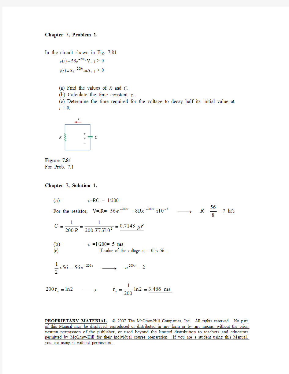
In the circuit shown in Fig. 7.81
(),V 56200t e t v ?= t > 0
(),mA 8200t e t i ?= t > 0
(a) Find the values of R and C . (b) Calculate the time constant τ.
(c) Determine the time required for the voltage to decay half its initial value at t = 0.
Figure 7.81 For Prob. 7.1
Chapter 7, Solution 1.
(a) τ=RC = 1/200
For the resistor, V=iR= 2002003
56
568Re 107 k 8
t t e x R ???=??→
=
=? 3
11
0.7143200200710C F R X X μ=
== (b) τ =1/200= 5 ms
(c) If value of the voltage at = 0 is 56 .
?=??→
=2002001
565622
t t x e e
=??→
=
=1
200ln2
ln2 3.466 ms 200
o o t t
PROPRIETARY MATERIAL . ? 2007 The McGraw-Hill Companies, Inc. All rights reserved. No part of this Manual may be displayed, reproduced or distributed in any form or by any means, without the prior written permission of the publisher, or used beyond the limited distribution to teachers and educators
Find the time constant for the RC circuit in Fig. 7.82.
Figure 7.82 For Prob. 7.2.
Chapter 7, Solution 2.
C R th =τ
where th R is the Thevenin equivalent at the capacitor terminals.
?=+=601280||120R th
=××=τ-3105.060ms 30
Chapter 7, Problem 3.
Determine the time constant for the circuit in Fig. 7.83.
Figure 7.83 For Prob. 7.3.
Chapter 7, Solution 3.
R = 10 +20//(20+30) =10 + 40x50/(40 + 50)=32.22 k ?
31232.221010010 3.222 S RC X X X τμ?===
PROPRIETARY MATERIAL . ? 2007 The McGraw-Hill Companies, Inc. All rights reserved. No part of this Manual may be displayed, reproduced or distributed in any form or by any means, without the prior written permission of the publisher, or used beyond the limited distribution to teachers and educators
The switch in Fig. 7.84 moves instantaneously from A to B at t = 0. Find v for t > 0.
Figure 7.84 For Prob. 7.4.
Chapter 7, Solution 4.
For t<0, v(0-)=40 V.
For t >0. we have a source-free RC circuit.
3621010100.02RC x x x τ?===
/50()(0)40V t t v t v e e τ??==
PROPRIETARY MATERIAL . ? 2007 The McGraw-Hill Companies, Inc. All rights reserved. No part of this Manual may be displayed, reproduced or distributed in any form or by any means, without the prior written permission of the publisher, or used beyond the limited distribution to teachers and educators
For the circuit shown in Fig. 7.85, find i (t ), t > 0.
Figure 7.85 For Prob. 7.5.
Chapter 7, Solution 5.
Let v be the voltage across the capacitor. For t <0,
4
(0)16 V 24
v ?==+ For t >0, we have a source-free RC circuit as shown below.
?
v
1
(45)3RC s τ==+=
//3()(0)16t t v t v e e τ??==
/3/311
()()
16 1.778 A 33
t t dv i t C e e dt ??=?=??=
PROPRIETARY MATERIAL . ? 2007 The McGraw-Hill Companies, Inc. All rights reserved. No part of this Manual may be displayed, reproduced or distributed in any form or by any means, without the prior written permission of the publisher, or used beyond the limited distribution to teachers and educators
The switch in Fig. 7.86 has been closed for a long time, and it opens at t = 0. Find v (t ) for t ≥ 0.
Figure 7.86 For Prob. 7.6.
Chapter 7, Solution 6.
V
e 4)t (v 25
210x 2x 10x 40RC ,e v )t (v V 4)24(2
102
)0(v v t 5.1236/t o o ??τ?====τ==+=
=
PROPRIETARY MATERIAL . ? 2007 The McGraw-Hill Companies, Inc. All rights reserved. No part of this Manual may be displayed, reproduced or distributed in any form or by any means, without the prior written permission of the publisher, or used beyond the limited distribution to teachers and educators
Assuming that the switch in Fig. 7.87 has been in position A for a long time and is moved to position B at t =0, find v 0(t ) for t ≥ 0.
Figure 7.87 For Prob. 7.7.
Chapter 7, Solution 7.
When the switch is at position A, the circuit reaches steady state. By voltage division,
=
=+40
(0)(12)84020
o v V V When the switch is at position B, the circuit reaches steady state. By voltage division,
30
()(12)7.23020o v V V ∞=
=+ 2030
20//301250
Th x R k k k ==
=? 33121021024Th R C x x x s τ?===
//24/24()()[(0)()]7.2(87.2)7.20.8 V t t t o o o o v t v v v e e e τ???=∞+?∞=+?=+
PROPRIETARY MATERIAL . ? 2007 The McGraw-Hill Companies, Inc. All rights reserved. No part of this Manual may be displayed, reproduced or distributed in any form or by any means, without the prior written permission of the publisher, or used beyond the limited distribution to teachers and educators
For the circuit in Fig. 7.88, if v = 10e t 4? V and
i = 0.2e t 4?A , t > 0
(a) Find R and C .
(b) Determine the time constant.
(c) Calculate the initial energy in the capacitor.
(d) -Obtain the time it takes to dissipate 50 percent of the initial energy.
Figure 7.88 For Prob. 7.8.
Chapter 7, Solution 8.
(a)
4
1RC ==τ dt
dv C
i -= =?→?=C e -4))(10(C e 0.2--4t
-4t mF 5
==C
41
R ?50
(b) ===τ41
RC s 25.0
(c) =×==)100)(105(21
CV 21)0(w 3-20C mJ 250
(d)
()?=×=02t -2020R e 1CV 2
1
CV 2121w
2
1
e e 15.0008t -8t -=?→??=
or 2e 08t =
==)2(ln 8
1
t 0ms 6.86
PROPRIETARY MATERIAL . ? 2007 The McGraw-Hill Companies, Inc. All rights reserved. No part of this Manual may be displayed, reproduced or distributed in any form or by any means, without the prior written permission of the publisher, or used beyond the limited distribution to teachers and educators
The switch in Fig. 7.89 opens at t = 0. Find v 0 for t > 0
Figure 7.89 For Prob. 7.9.
Chapter 7, Solution 9.
For t < 0, the switch is closed so that
4
(0) 4 V 24
o v ==+
For t >0, we have a source-free RC circuit. 3331041012RC x x x s τ?===
//12()(0)4V t t o o v t v e e τ??==
PROPRIETARY MATERIAL . ? 2007 The McGraw-Hill Companies, Inc. All rights reserved. No part of this Manual may be displayed, reproduced or distributed in any form or by any means, without the prior written permission of the publisher, or used beyond the limited distribution to teachers and educators
For the circuit in Fig. 7.90, find v 0(t ) for t > 0. Determine the time necessary for the capacitor voltage to decay to one-third of its value at t = 0.
Figure 7.90 For Prob. 7.10.
Chapter 7, Solution 10.
For t<0, 3
(0)(36)9 V 39
v V ?=
=+ For t>0, we have a source-free RC circuit 3631020100.06RC x x x s τ?===
v o (t) = 9e –16.667t V
Let the time be t o .
3 = 9e –16.667to or e 16.667to = 9/3 = 3
t o = ln(3)/16.667 = 65.92 ms .
PROPRIETARY MATERIAL . ? 2007 The McGraw-Hill Companies, Inc. All rights reserved. No part of this Manual may be displayed, reproduced or distributed in any form or by any means, without the prior written permission of the publisher, or used beyond the limited distribution to teachers and educators For the circuit in Fig. 7.91, find i 0 for t
> 0.
Figure 7.91 For Prob. 7.11.
Chapter 7, Solution 11.
For t<0, we have the circuit shown below.
3 ? 4H
?
i o
8 A ?
3//4= 4x3/7=1.7143
1.7143
(0)(8) 1.4118o i ?=
=+ A For t >0, we have a source-free RL circuit.
41/348
L R τ===+
/3()(0) 1.4118 A t t o o i t i e e τ??==
PROPRIETARY MATERIAL . ? 2007 The McGraw-Hill Companies, Inc. All rights reserved. No part of this Manual may be displayed, reproduced or distributed in any form or by any means, without the prior written permission of the publisher, or used beyond the limited distribution to teachers and educators
The switch in the circuit of Fig. 7.92 has been closed for a long time. At t = 0 the switch is opened. Calculate i (t ) for t > 0.
Figure 7.92 For Prob. 7.12.
Chapter 7, Solution 12.
When t < 0, the switch is closed and the inductor acts like a short circuit to dc. The 4 ? resistor is short-circuited so that the resulting circuit is as shown in Fig. (a).
A 43
12
)0(i ==
? Since the current through an inductor cannot change abruptly,
A 4)0(i )0(i )0(i ===+?
When t > 0, the voltage source is cut off and we have the RL circuit in Fig. (b).
5.04
2
R L ===τ
Hence,
==τt -e )0(i )t (i A e 4-2t
4 ?(b)
3 ?
(a)
i(0-)
PROPRIETARY MATERIAL . ? 2007 The McGraw-Hill Companies, Inc. All rights reserved. No part of this Manual may be displayed, reproduced or distributed in any form or by any means, without the prior written permission of the publisher, or used beyond the limited distribution to teachers and educators
In the circuit of Fig. 7.93,
v (t ) = 20e t 3
10? V, t > 0 i (t ) = 4e t
310? mA,
t > 0
(a) Find R , L , and τ.
(b) Calculate the energy dissipated in the resistance for 0 < t < 0.5 ms.
Figure 7.93 For Prob. 7.13.
Chapter 7, Solution 13.
(a) 31
110
ms τ==
10001000320410t t v iR e Rx e x ???=??→= From this, R = 20/4 k ?= 5 k ?
But 35100015101000
L
x L H R τ==??→=
=
(b) The energy dissipated in the resistor is
?????===?∫∫3
33
33
2102103
0.51080108010210
t
t
x x t
x x w pdt x e
dt e x 140(1)25.28e J J μμ?=?=
PROPRIETARY MATERIAL . ? 2007 The McGraw-Hill Companies, Inc. All rights reserved. No part of this Manual may be displayed, reproduced or distributed in any form or by any means, without the prior written permission of the publisher, or used beyond the limited distribution to teachers and educators Calculate the time constant of the circuit in Fig. 7.94.
Figure 7.94 For Prob. 7.14.
Chapter 7, Solution 14.
6040
(4020)//(1030)24100
Th x R k =++=
=? 3
3
510/0.20832410
x L R s x τμ?===
Chapter 7, Problem 15.
Find the time constant for each of the circuits in Fig. 7.95.
Figure 7.95 For Prob. 7.15.
Chapter 7, Solution 15 (a) s R L
R Th Th 25.020/5,2040//1012===
?=+=τ (b) ms 5.040/)1020(,
408160//403===?=+=?x R L R Th
Th τ
PROPRIETARY MATERIAL . ? 2007 The McGraw-Hill Companies, Inc. All rights reserved. No part of this Manual may be displayed, reproduced or distributed in any form or by any means, without the prior written permission of the publisher, or used beyond the limited distribution to teachers and educators
Determine the time constant for each of the circuits in Fig. 7.96.
Figure 7.96 For Prob. 7.16.
Chapter 7, Solution 16.
eq
eq R L =τ
(a)
L L eq = and 3
13
131231312eq R R R R )R R (R R R R R R R +++=++
=
=τ3
131231R R )R R (R )
R R (L +++
(b) where
2121eq L L L L L += and 2
121213212
13eq R R R R )R R (R R R R R R R +++=++= =τ)
R R )R R (R ()L L ()
R R (L L 21213212121++++
PROPRIETARY MATERIAL . ? 2007 The McGraw-Hill Companies, Inc. All rights reserved. No part
of this Manual may be displayed, reproduced or distributed in any form or by any means, without the prior written permission of the publisher, or used beyond the limited distribution to teachers and educators
Consider the circuit of Fig. 7.97. Find v 0(t ) if i (0) = 2 A and v (t ) = 0.
Figure 7.97 For Prob. 7.17.
Chapter 7, Solution 17. τ=t -e )0(i )t (i ,
16
1441R L
eq ===
τ
-16t e 2)t (i =
16t -16t -o e 2)16-)(41(e 6dt
di
L i 3)t (v +=+=
=)t (v o V )t (u e 2--16t
PROPRIETARY MATERIAL . ? 2007 The McGraw-Hill Companies, Inc. All rights reserved. No part
of this Manual may be displayed, reproduced or distributed in any form or by any means, without the prior written permission of the publisher, or used beyond the limited distribution to teachers and educators
For the circuit in Fig. 7.98, determine v 0 (t ) when i (0) = 1 A and v (t ) = 0.
Figure 7.98 For Prob. 7.18.
Chapter 7, Solution 18. If 0)t (v =, the circuit can be redrawn as shown below.
563||2R eq =
=, 3
1
6552R L =×==τ -3t t -e e )0(i )t (i ==τ
==
=3t -o e -3)(52
-dt di -L )t (v V e 2.1-3t
PROPRIETARY MATERIAL . ? 2007 The McGraw-Hill Companies, Inc. All rights reserved. No part of this Manual may be displayed, reproduced or distributed in any form or by any means, without the prior written permission of the publisher, or used beyond the limited distribution to teachers and educators
In the circuit of Fig. 7.99, find i (t ) for t > 0 if i (0) = 2 A.
Figure 7.99 For Prob. 7.19.
Chapter 7, Solution 19.
To find th R we replace the inductor by a 1-V voltage source as shown above.
0i 401i 1021=+?
But 2i i i 2+= and 1i i = i.e. i i 2i 21==
30
1
i 0i 201i 10=?→?
=+?
?==30i 1
R th
s 2.030
6R L th ===τ
=)t (i A )t (u e 2-5t
1 V
10 ??
PROPRIETARY MATERIAL . ? 2007 The McGraw-Hill Companies, Inc. All rights reserved. No part of this Manual may be displayed, reproduced or distributed in any form or by any means, without the prior written permission of the publisher, or used beyond the limited distribution to teachers and educators
For the circuit in Fig. 7.100, v = 120e t 50? V
and i = 30e t 50?A, t > 0
(a) Find L and R .
(b) Determine the time constant.
(c) Calculate the initial energy in the inductor.
(d) What fraction of the initial energy is dissipated in 10 ms?
Figure 7.100 For Prob. 7.20.
Chapter 7, Solution 20.
(a) L 50R 501
R L =?→?=
=τ
dt
di L v -=
=?→?=L e -50))(30(L e 120-50t -50t - 80 mH
==L 50R 4 ?
(b)
===τ50
1R L ms 20 (c)
===22)30)(08.0(2
1)0(i L 21
w 36J The value of the energy remaining at 10 ms is given by:
w 10 = 0.04(30e –0.5)2 = 0.04(18.196)2 = 13.24J.
So, the fraction of the energy dissipated in the first 10 ms is given by:
(36–13.24)/36 = 0.6322 or 63.2%.
PROPRIETARY MATERIAL . ? 2007 The McGraw-Hill Companies, Inc. All rights reserved. No part
of this Manual may be displayed, reproduced or distributed in any form or by any means, without the prior written permission of the publisher, or used beyond the limited distribution to teachers and educators
In the circuit of Fig. 7.101, find the value of R for which the steady-state energy
stored in the inductor will be 1 J.
Figure 7.101 For Prob. 7.21.
Chapter 7, Solution 21.
The circuit can be replaced by its Thevenin equivalent shown below.
V 40)60(40
8080
V th =+=
R 380
R 80||40R th +=+=
R 38040
R V )(i )0(i I th th +=
=∞== 1380
R 40)2(21I L 21w 2
2=??
?
?
??+== 340
R 1380R 40=?→?=+
=R ?333.13
2 H
R th
V
PROPRIETARY MATERIAL . ? 2007 The McGraw-Hill Companies, Inc. All rights reserved. No part of this Manual may be displayed, reproduced or distributed in any form or by any means, without the prior written permission of the publisher, or used beyond the limited distribution to teachers and educators
Find i (t ) and v (t ) for t > 0 in the circuit of Fig. 7.102 if i (0) = 10 A.
Figure 7.102 For Prob. 7.22.
Chapter 7, Solution 22.
τ
=t -e )0(i )t (i ,
eq
R L
=τ
?=+=5120||5R eq , 5
2=τ
=)t (i A e 10-2.5t
Using current division, the current through the 20 ohm resistor is
2.5t -o e -25i --i)(2055i ==+=
==o i 20)t (v V e 04--2.5t
电路分析基础课程教学大纲
《电路分析基础B》课程教学大纲(56+0学时) 一、课程基本情况 二.课程性质与任务 《电路分析基础》是电类专业的一门重要的学科基础课。本课程的主要任务是研究电路的基本定理、定律、基本分析方法及应用。本课程的目标是使学生通过对本课程的学习,理解电路分析的基本概念,掌握其分析方法、定理和定律并能灵活应用于电路分析中,使学生在分析问题和解决问题的能力上得到培养和提高,为后续课程的学习奠定坚实的理论基础。 课程思政部分要求:在教学过程中融入爱国教育、社会责任、人生领悟、民族自信、感恩等多种育人要素,倡导科学研究中的科学精神、创新精神和工匠精神,实现教师和学生的知识、情感及价值等方面的共鸣。 三. 课程主要教学内容及学时分配
四.课程教学基本内容和基本要求 第一章基础知识( 5学时) [知识点]:电路分析基本变量(电流、电压和功率)的概念;线性电阻元件和独立源的定义及伏安关系;基尔霍夫电流定律和基尔霍夫电压定律;受控源。 [重点] 电流、电压、功率及参考方向的概念,电路的两类约束关系(元件约束和拓扑约束) [难点] 电流、电压真实方向与参考方向关系、关联非关联参考下功率计算及功率正负含义,受控源电路分析 [基本要求] 1、理解电路分析基本变量(电流、电压和功率)的概念;2、掌握线性电阻元件和独立源的定义及伏安关系;3、熟练掌握基尔霍夫电流定律和基尔霍夫电压定律;4、理解受控源的概念。 [实践与练习] 课后作业布置建议: 习题:1-1、1-2、1-3 、1-5、1-6、1-12、1-9、1-13、1-17 、1-30、1-31。 课程思政映射点:由电压、电流单位以物理学家伏特和安培名字命名,以及基尔霍夫21岁提出基尔霍夫定律,引导学生敬畏科学家、崇尚科学精神。 第二章等效变换分析法( 5学时) [知识点]:单口网络等效条件;实际电源的两种电路模型及其等效变换;无源和含源单口网络的等效化简;T~π等效变换。 [重点]:单口网络的等效条件,单口网络的等效化简方法;
《电路理论基础》(第三版 陈希有)习题答案第一章
答案1.1 解:图示电路电流的参考方向是从a 指向b 。当时间t <2s 时电流从a 流向b,与参考方向相同,电流为正值;当t >2s 时电流从b 流向a ,与参考方向相反,电流为负值。所以电流i 的数学表达式为 2A 2s -3A 2s t i t ? 答案1.2 解:当0=t 时 0(0)(59e )V 4V u =-=-<0 其真实极性与参考方向相反,即b 为高电位端,a 为低电位端; 当∞→t 时 ()(59e )V 5V u -∞∞=-=>0 其真实极性与参考方向相同, 即a 为高电位端,b 为低电位端。 答案1.3 解:(a)元件A 电压和电流为关联参考方向。元件A 消耗的功率为 A A A p u i = 则 A A A 10W 5V 2A p u i === 真实方向与参考方向相同。 (b) 元件B 电压和电流为关联参考方向。元件B 消耗的功率为 B B B p u i = 则 B B B 10W 1A 10V p i u -===- 真实方向与参考方向相反。 (c) 元件C 电压和电流为非关联参考方向。元件C 发出的功率为 C C C p u i = 则 C C C 10W 10V 1A p u i -===-
真实方向与参考方向相反。 答案1.4 解:对节点列KCL 方程 节点③: 42A 3A 0i --=,得42A 3A=5A i =+ 节点④: 348A 0i i --+=,得348A 3A i i =-+= 节点①: 231A 0i i -++=,得231A 4A i i =+= 节点⑤: 123A 8A 0i i -++-=,得123A 8A 1A i i =+-=- 若只求2i ,可做闭合面如图(b)所示,对其列KCL 方程,得 28A-3A+1A-2A 0i -+= 解得 28A 3A 1A 2A 4A i =-+-= 答案1.5 解:如下图所示 (1)由KCL 方程得 节点①: 12A 1A 3A i =--=- 节点②: 411A 2A i i =+=- 节点③: 341A 1A i i =+=- 节点④: 231A 0i i =--= 若已知电流减少一个,不能求出全部未知电流。 (2)由KVL 方程得
电路理论基础
1:电位是相对的量,其高低正负取决于()。 回答:参考点 2:不能独立向外电路提供能量,而是受电路中某个支路的电压或电流控制的电源叫()。 回答:受控源 3:振幅、角频率和()称为正弦量的三要素。 回答:初相 4:并联的负载电阻越多(负载增加),则总电阻越()。 回答:小 5:任一电路的任一节点上,流入节点电流的代数和等于()。 回答:零 6:电流的基本单位是()。 回答:安培 7:与理想电压源()联的支路对外可以开路等效。 回答:并 8:电气设备只有在()状态下工作,才最经济合理、安全可靠。 回答:额定 9:通常规定()电荷运动的方向为电流的实际方向。 回答:正 10:电容元件的电压相位()电流相位。 回答:滞后 11:两个同频率正弦量之间的相位差等于()之差。 回答:初相 12:电位是相对于()的电压。 回答:参考点 13:支路电流法原则上适用适用于支路数较()的电路。 回答:少 14:电压定律是用来确定回路中各段()之间关系的电路定律。 回答:电压
15:KCL和KVL阐述的是电路结构上()的约束关系,取决于电路的连接形式,与支路元件的性质()。 回答:电压与电流、无关 16:各种电气设备或元器件的电压、电流及功率都规定一个限额,这个限额值就称为电气设备的()。 回答:额定值 17:节点电压法适用于支路数较()但节点数较少的复杂电路。 回答:多 18:三个电阻元件的一端连接在一起,另一端分别接到外部电路的三个节点的连接称()连接。 回答:星形 19:提高功率因数的原则是补偿前后()不变。 回答:P U 20:交流电可通过()任意变换电流、电压,便于输送、分配和使用。回答:变压器 1:任一时刻,沿任一回路参考方向绕行方向一周,回路中各段电压的代数和恒等于()。 回答:零 2:对于两个内部结构和参数完全不同的二端网络,如果它们对应端钮的伏安关系完全相同,则称N1和N2是()的二端网络。 回答:相互等效 3:叠加定理只适用于线性电路求()和() 回答:电压电流 4:对一个二端网络来说,从一个端钮流入的电流一定等于另一个端钮()的电流。 回答:流出
电路分析基础习题及答案
电路分析基础 练习题 @ 微笑、敷衍心痛。 1-1 在图题1-1所示电路中。元件A 吸收功率30W ,元件B 吸收功率15W ,元件C 产生功率30W ,分别求出三个元件中的电流I 1 、I 2 、I 3。 解 61=I A ,32-=I A ,63=I A 1-5 在图题1-5所示电路中,求电流I 和电压U AB 。 解 1214=--=I A ,39442103=?+?+=AB U V 1-6 在图题1-6所示电路中,求电压U 。 解 U +?-=253050,即有 30=U V 1-8 在图题1-8所示电路中,求各元件的功率。 解 电阻功率:12322 3=?=ΩP W , 82/422==ΩP W 电流源功率:0)6410(22=--=A P , 4141-=?-=A P W + -V 51 I A 2 I B - +V 5-+ - V 53 I C 图题1-1 Ω 3V 5-+-+ V 4Ω 1Ω 22 I 1 I - + - + Ω 5V 30A 2U - + V 50图题1-6 图题1-7 V 10Ω 3-+ Ω 2A 2A 1-+ V 4
电压源功率:2021010-=?-=V P W , 4)221(44=-+=V P W 2-7 电路如图题2-7所示。求电路中的未知量。 解 1262=?=S U V 3 4 9122== I A 112/12/33===S U P I A 3/1313/420=++=I A Ω== 12112 3R Ω===13 36 3/13120I U R S eq 2-9 电路如图题2-9所示。求电路中的电流1I 。 解 从图中可知,2Ω与3Ω并联, 由分流公式,得 1123553 I I I =?= 11 1 3==I A 所以,有 131321+=+=I I I I 解得 5.01-=I A 2-8 电路如图题2-8所示。已知213I I =,求电路中的电阻R 。 解 KCL :6021=+I I 213I I = 解得 451=I mA, 152=I mA. R 为 6.615 45 2.2=?=R k Ω 解 (a)由于有短路线,Ω=6AB R , (b) 等效电阻为 Ω=+=++=1.15 .25 .15.01//)1//11(1//1AB R 2-12 电路如图题2-12所示。求电路AB 间的等效电阻AB R 。 I 3 R Ω6Ω 9eq R S U A 22 I 3I W 123=P 图题2-7 V 1- + Ω 3Ω 1Ω 21 I 1 5I 图题2-9 2 I 3I Ω k 2.2R 0mA 62 I 1I 图题2-8
电路理论基础第三版 答案 陈希有
答案2.1 解:本题练习分流、分压公式。设电压、电流参考方向如图所示。 (a) 由分流公式得: 23A 2A 23 I R Ω?==Ω+ 解得 75R =Ω (b) 由分压公式得: 3V 2V 23 R U R ?==Ω+ 解得 47 R =Ω
答案2.2 解:电路等效如图(b)所示。 20k Ω 1U + - 20k Ω + _ U 图中等效电阻 (13)520 (13)k //5k k k 1359 R +?=+ΩΩ=Ω=Ω++ 由分流公式得: 220mA 2mA 20k R I R =? =+Ω 电压 220k 40V U I =Ω?= 再对图(a)使用分压公式得: 13==30V 1+3 U U ?
答案2.3 解:设2R 与5k Ω的并联等效电阻为 2 325k 5k R R R ?Ω =+Ω (1) 由已知条件得如下联立方程: 32 1 13130.05(2)40k (3)eq R U U R R R R R ?==?+??=+=Ω? 由方程(2)、(3)解得 138k R =Ω 32k R =Ω 再将3R 代入(1)式得 210k 3 R =Ω
答案2.4 解:由并联电路分流公式,得 1 8 20mA8mA (128) I Ω =?= +Ω 2 6 20mA12mA (46) I Ω =?= +Ω 由节点①的KCL得 128mA12mA4mA I I I =-=-=-
答案2.5 解:首先将电路化简成图(b)。 图 题2.5 120Ω 图中 1(140100)240R =+Ω=Ω 2(200160)120270360(200160)120R ??+?=+Ω=Ω??++?? 由并联电路分流公式得 2 112 10A 6A R I R R =?=+ 及 21104A I I =-= 再由图(a)得 32120 1A 360120 I I =? =+ 由KVL 得, 3131200100400V U U U I I =-=-=-
(完整版)教学大纲-电子科技大学教务处
《电子技术基础实验Ⅰ》课程教学大纲 课程英文名称:Fundadamentals of Electronic Technology Lab Ⅰ 课程代码:E0200710 学时数:20 学分数:1 课程类型:实验课程 适用学科专业:电子类专业 先修课程:电路分析 执笔者:崔红玲编写日期:2013-11-15 审核人: 一、课程简介 本课程是电子信息工程、通信工程等电子类专业的一门重要实验课程,以“电路分析基础”作为背景知识,在服务于理论课程的同时,注重引导学生建立工程上的感性认识,认识常用的电子元器件,学会使用常用的电子测量仪器,学会简单的电子测量方法,能够设计搭建简单的单元电路。 一、Introduction This course is an important experiment course in electronic and communication engineering. Based on the “Basic Theories of Circuit Analysis”, this course not only serves for the theory courses, but also aims at helping students have a perceptual cognition on electronic engineering projects. Students in this course will be able to know about basic electronic components, use electronic measurement devices, handle simple electronic measurement methods, and design and build the basic circuit unit. 二、课程目标 引导学生建立工程上的感性认识,增强培养学生实践动手能力。通过设计单元电路引导 学生学会应用理论知识,通过预设的问题和实验中遇到的小故障,引导学生学会独立思考, 培养学学生独立分析问题、解决问题的能力。 二、Goals The course will guide the students to have a perceptual cognition on electronic engineering -on ability. Student will be able to apply the electronic theory and thus improve the students’ hands practically by designing the circuit unit. Also, They will have the ability to think independently by solving the problems and faults in the experiments. These teaching activities will enhance
通信工程专业本科学分制培养方案
通信工程专业本科学分制培养方案 (一)专业培养目标 本专业培养具备通信技术、通信系统和通信网等方面的知识,能在通信领域中从事研究、设计、制造、运营及在国民经济各部门和国防工业中从事开发、应用通信技术与设备的高素质应用型工程技术人才。 (二)专业培养基本要求 本专业学生主要学习通信系统和通信网方面的基础理论、组成原理和设计方法,受到通信工程实践的基本训练,具备从事现代通信系统和网络的设计、开发、调测和工程应用的基本能力。 毕业生应获得以下几方面的知识和能力: 1、掌握通信领域内的基本理论和基础知识; 2、掌握光波、无线、多媒体等通信技术; 3、掌握通信系统和通信网的分析和设计方法; 4、具有设计、开发、调测、应用通信系统和通信网的基本能力; 5、了解通信系统和通信网建设的基本方针、政策和法规; 6、了解通信技术的最新进展与发展动态; 7、掌握文献检索、资料查询的基本方法,具有一定的科学研究和实际工作能力。 (三)主干学科 信息与通信工程、计算机科学与技术。 (四)主要课程 高等数学、大学物理学、电路分析基础、模拟电子技术、数字电子技术、信号与系统、通信电子线路、数字信号处理、现代通信原理、信息论与编码理论、现代交换原理、计算机通信网、移动通信、光纤通信、微型计算机原理与应用、电磁场与电磁波、单片机原理及应用等。 (五)主要实践性教学环节
(六)主要专业实验 本专业还开设以下主要非单列实验课程,学分与理论课统一计算,此处不单列: (七)修业年限及学分要求 1、学制:四年,修业年限:三至六年。 2、学分要求:修业期间至少需修完170学分。其中包括实践性教学项目19学分,公共选修课(含必读书目8个)16学分。 3、学分及比例: 公共必修课,共47学分,(包括社会实践2学分、军训2学分),占总学分27.6%; 专业必修课,共73学分(包括专业见习1学分,生产实习6学分,毕业设计8学分),占总学分42.9%; 专业选修课,需修满34学分,占总学分20%; 公共选修课,需修满16学分(包括必读书目8学分),占总学分9.4%。 4、公共选修课课程及学分按《延安大学本科学分制公共选修课实施办法》执行。 5、必读书目考核及学分按《延安大学本科生必读书目成绩考核办法》执行。 (八)授予学位和学位课程 授予学位:工学学士 学位课程:
《电路理论基础》(第三版 陈希有)习题答案第十章
答案10.1 解:0
s 1.0i ==C R τ 0>t 后电路为零输入响应,故电容电压为: V e 6.0e )0()(10/t t C C u t u --+==τ Ω6电阻电压为: V e 72.0)d d (66)(101t C t u C i t u -=-?Ω-=?Ω-=)0(>t 答案10.4 解:0
电路分析基础教学大纲
《电路分析基础》课程教学大纲 课程英文名称:Theory of circuit 课程编号:1510064002 课程计划学时:80(授课学时:64 实验学时:16) 学分:4.5 课程简介: 电路分析基础课程是自动化、电气工程及其自动化、测控技术、电子信息工程、电子信息科学与技术、电子科学与技术、通讯工程等专业的一门重要技术基础课,通过本课程的学习,使学生掌握电路的基本理论,分析电路的基本方法,以及进行实验的初步技能,并为后续课准备必要的电路知识。电路分析基础课程理论严密,逻辑性强,对学生的辨证思维能力的培养和树立理论联系实际的科学观点及提高学生分析问题解决问题的能力,都有重要的作用。 一、课程教学内容及教学基本要求 第一章电路模型和电路定律 本章重点是电流和电压参考方向的概念、功率的计算、电路元件特性、以及基尔霍夫定律,难点是参考方向的概念及应用、基尔霍夫定律的应用。全章课堂讲授6学时,实验1学时。 第一节电路及电路模型 要求了解电路的作用(考核概率1%),理解实际电路的电路图和电路模型(考核概率1%),掌握电路的组成及各组成部分的作用(考核概率80%)。 1.电路的组成及各组成部分的作用:电源、负载和中间环节。 2.电路的作用:实现电能的传输和变换,实现信号的传递和处理。 3.实际电路的电路图和电路模型。 第二节电流、电压参考方向 理解电流、电压参考方向的含义(考核概率50%)。 第三节电功率和能量 理解功率的定义(考核概率50%),掌握功率的计算方法(考核概率80%)。 1.功率的定义 2.功率计算方法 第四节电路元件 要求了解电路集总参数的概念(考核概率1%)。
《电路理论基础》(第三版 陈希有)习题答案第七章
答案 解:设星形联接电源电路如图(a)所示,对称星形联接的三相电源线电压有效值 倍,相位上超前前序相电压30?。即 AB 3030)V=538.67cos()V u t t ωω=-?+? BC 538.67cos(120)V u t ω=-? CA 538.67cos(240)V u t ω=-? 各相电压和线电压的相量图可表达如图(b)所示。 A B C N (a) BC U BN U U (b) CN U -AN BN U - 答案 解:题给三个相电压虽相位彼此相差120,但幅值不同,属于非对称三相电压,须按KVL 计算线电压。设 AN 127V U = BN 127240V=(-63.5-j110)V U =∠? CN 135120V=(-67.5+j116.9)V U =∠? 则 AB AN BN BC BN CN CA CN AN (190.5j 110)V 22030V (4j226.9)V 226.989V (194.5j 116.9)V 226.9149V U U U U U U U U U =-=+=∠?=-=-=∠-?=-=-+=∠? 即线电压有效值分别为220V ,226.9V ,226.9V 。 答案 设负载线电流分别为A B C i i i 、、,由KCL 可得A B C 0I I I =++。又A B C 10A I I I ===,则A B C i i i 、、的相位彼此相差120?,符合电流对称条件,即线电流是对称的。 但相电流不一定对称。例如,若在三角形负载回路内存在环流0I (例如,按三角形联接的三相变压器),则负载相电流不再对称,因为 CA CA 0 BC BC 0 AB AB ',','I I I I I I I I I +=+=+= 不满足对称条件。而该环流对线电流却无影响,因为每个线电流都是两个相
电路理论基础试卷
一、填空题:(每空1分,1x20=20分) 1.线性电路线性性质的最重要体现就是性和性,它们反映了电路中激励与响应的内在关系。 2.理想电流源的是恒定的,其是由与其相连的外电路决定的。 3.KVL是关于电路中受到的约束;KCL则是关于电路中 受到的约束。 4.某一正弦交流电压的解析式为u=102cos(200πt+45°)V,则该正弦电流的有效值U= V,频率为f= H Z,初相φ= 。当t=1s 时,该电压的瞬时值为V。 5.一个含有6条支路、4个节点的电路,其独立的KCL方程有_____ _个,独立的KVL 方程有个;若用2b方程法分析,则应有_ _ ___个独立方程。 6.有一L=0.1H的电感元件,已知其两端电压u=1002cos(100t-40°)V,则该电感元件的阻抗为____________Ω,导纳为___________S,流过电感的电流(参考方向与u关联)i= A。 7.已知交流电流的表达式:i1= 10cos(100πt-70°)A ,i2=3cos(100πt+130°)A,则i1超前(导前)i2_________ 。 8.功率因数反映了供电设备的率,为了提高功率因数通常采用 补偿的方法。 9.在正弦激励下,含有L和C的二端网络的端口电压与电流同相时,称电路发生了。 二、简单计算填空题:(每空2分,2x14=28分) 1.如图1所示电路中,电流i= A。 2.如图2所示电路中,电压U ab= V。
3.如图3所示二端网络的入端电阻R ab= Ω。 4.如图4所示电路中,电流I= A。 5.如图5所示为一有源二端网络N,在其端口a、b接入电压表时,读数为10V,接入电流表时读数为5A,则其戴维南等效电路参数U OC= V, R O= Ω。 6.如图6所示为一无源二端网络P,其端口电压u与电流i取关联参考方向,已知u=10cos(5t +30°)V, i=2sin(5t+60°)A,则该二端网络的等效阻抗Z ab= Ω,吸收的平均功率P= W,无功功率Q= Var。
《电路理论基础》(第三版--陈希有)习题答案第三章
答案3.1 解:应用置换定理,将电阻R 支路用0.5A I =电流源代替,电路如图(b)所示。 I 2 对电路列节点电压方程: 1212(1)0.5A 44n n I U U +Ω?-=-ΩΩ 12116V (1)3 4.5 4.5n n U U -+Ω++?= ΩΩΩ 0.5A I = 解得 11V n U = 则 12n U R I ==Ω 答案3.2 解: (a ) 本题考虑到电桥平衡,再利用叠加定理,计算非常简单。 (1)3V 电压源单独作用,如图(a-1)、(a-2)所示。 (a-1)(a-2) 由图(a-2)可得 '3V 1A 148348 I ==?Ω+Ω+ 由分流公式得: ''182 A 483 I I Ω=-?=-Ω+Ω (2)1A 电流源单独作用,如图(a-3)所示。
(a-3) 考虑到电桥平衡, "0I =, 在由分流公式得: "113 1A A 134I =-?=-+ (3)叠加: '"1A I I I =+= '"11117/12A I I I =+=- 2 111 2.007W P I Ω=?= (b ) (1)4V 电压源单独作用,如图(b-1)所示。 '2 I ' (b-1) 由图(b-1)可得, '24V 2V (2+2)U Ω?= =Ω '136A I U =-=- ''21'5A I I I =+=- (2)2A 电流源单独作用,如图(b-2)所示。
(b-2) ''22 2A=2V 22U ?= Ω?+ "'' 2311A 2 I I =?= 对节点②列KCL 方程得, """1132A 4A I U I +== 对节点③列KCL 方程得, "" "230I I U ++= 解得 "5A I = (3) 叠加 '"1116A 4A=10A I I I =+=--- '"5A 5A=10A I I I =+=--- 2111 100W P I Ω=?Ω= 答案3.3 解 :利用叠加定理,含源电阻网络中的电源分为一组,其作用为' I ,如图(b)所示。S I 为一组,其单独作用的结果I '' 与S I 成比例,即: "S I kI =,如图(c)所示。 I I s kI (a) (b) (c) + '"'S I I I I kI =+=+ (1) 将已知条件代入(1)式得 ' ' 04A 1A 2A I k I k ?=+???-=+???
《电路分析基础》第2版-习题参考答案-2014-tjh
《 电 路 分 析基础》各章习题案 第1章习题参考答案 1-1(1)50W ;(2)300V 、25V ,200V 、75V ;(3)R 2=12.5Ω,R 3=100Ω,R 4=37.5Ω 1-2VA=8.5V ,Vm=6.5V , VB=0.5V ,VC=-12V ,VD=-19V ,Vp=-21.5V ,U AB=8V ,U BC=12.5, U DA =-27.5V 1-3电源(产生:A 、 B 元件 ;负载 (吸收: C 、D 元件; 电 路满足 衡 条件。 1-4(1)VA=100V ,VB=99V ,VC=97V ,VD=7V ,VE=5V ,VF=1V ,UAF=99V ,UCE=92V , U BE =94V ,U BF =98V ,U CA =-3V ;(2)V C =90V ,V B =92V ,V A =93V ,V E =-2V ,V F =-6V , VG=-7V ,U AF=99V ,UCE=92V ,U BE=94V ,U BF=98V ,U CA=-3V 1-5I ≈0.18A ,6度,2.7元 1-6I=4A ,I 1=11A ,I 2=19A 1-7(a)U=6V ,(b)U=24V ,(c)R=5Ω,(d)I=23.5A 1-8(1)i6=-1A ;(2)u4=10V ,u6=3V ;(3)P1=-2W 发出,P2=6W 吸收,P3=16W 吸收, P 4=-10W 发出,P 5=-7W 发出,P 6=-3W 发出 1-9I=1A ,U S =134V ,R ≈7.8Ω 1-10S 断开:U AB=-4.8V ,UAO=-12V ,UBO=-7.2V ;S 闭合:UAB=-12V ,U AO=-12V ,UBO=0V 1-11 支路3,节点2,网孔2,回路3 1-12节点电流方程:(A)I 1+I 3-I 6=0,(B)I 6-I 5-I 7=0,(C)I 5+I 4-I 3=0 回路电压方程:①I 6R 6+U S5+I 5R 5-U S3+I 3R 3=0,②-I 5R 5-U S5+I 7R 7-U S4=0,③-I 3R 3+ US3+US4+I1R2+I1R1=0 1-13U AB =11V ,I 2=0.5A ,I 3=4.5A ,R 3≈2.4Ω 1-14V A =60V ,V C =140V ,V D =90V ,U AC =-80V ,U AD =-30V ,U CD =50V 1-15I1=-2A ,I2=3A ,I3=-5A ,I4=7A ,I5=2A 第2章习题参考答案 2-12.4Ω,5A 2-2(1)4V ,2V ,1V ;(2)40mA ,20mA ,10mA 2-31.5Ω,2A ,1/3A 2-46Ω,36Ω 2-52A ,1A 2-61A 2-72A 2-81A 2-9I1=-1.4A ,I2=1.6A ,I3=0.2A 2-10I 1=0A ,I 2=-3A ,P 1=0W ,P 2=-18W
《电路理论基础》(第三版陈希有)习题答案第十章
答案 解:0
时间常数 s 1.0i ==C R τ 0>t 后电路为零输入响应,故电容电压为: V e 6.0e )0()(10/t t C C u t u --+==τ Ω6电阻电压为: V e 72.0)d d (66)(101t C t u C i t u -=-?Ω-=?Ω-=)0(>t 答案 解:0
CircuitAnalysis(电路分析基础英文版实用)
EIE209 Basic Electronics Basic circuit analysis Prof. C.K. Tse: Basic Circuit Analysis1
Fundamental quantities ?Voltage — potential difference bet. 2 points ?“across” quantity ?analogous to ‘pressure’ between two points ?Current — flow of charge through a material ?“through” quantity analogous to fluid flowing along a pipe ? Prof. C.K. Tse: Basic Circuit
Units of measurement n Voltage: volt (V) n Current: ampere (A) n NOT Volt, Ampere!! Prof. C.K. Tse: Basic Circuit
Direction and polarity n Current direction indicates the direction of flow of positive charge n Voltage polarity indicates the relative potential between 2 points: + assigned to a higher potential point; and – assigned to a lower potential point. n NOTE: Direction and polarity are arbitrarily assigned on circuit diagrams. Actual direction and polarity will be governed by the sign of the value. Prof. C.K. Tse: Basic Circuit
《电路理论基础》(第三版 陈希有)习题答案第七章
答案7.1 解:设星形联接电源电路如图(a)所示,对称星形联接的三相电源线电压有效值 倍,相位上超前前序相电压30?。即 AB 3030)V=538.67cos()V u t t ωω=-?+? BC 538.67cos(120)V u t ω=-? CA 538.67cos(240)V u t ω=-? 各相电压和线电压的相量图可表达如图(b)所示。 A B C N (a) AB U CA U BC U AN U BN U CN U (b) CN U -AN U -BN U 答案7.2 解:题给三个相电压虽相位彼此相差120,但幅值不同,属于非对称三相电压,须按KVL 计算线电压。设 AN 127V U = BN 127240V=(-63.5-j110)V U =∠? CN 135120V=(-67.5+j116.9)V U =∠? 则 AB AN BN BC BN CN CA CN AN (190.5j 110)V 22030V (4j226.9)V 226.989V (194.5j 116.9)V 226.9149V U U U U U U U U U =-=+=∠?=-=-=∠-?=-=-+=∠? 即线电压有效值分别为220V ,226.9V ,226.9V 。 答案7.3 设负载线电流分别为A B C i i i 、、,由KCL 可得A B C 0I I I =++。又 A B C 10A I I I ===,则A B C i i i 、、的相位彼此相差120?,符合电流对称条件,即线电流是对称的。 但相电流不一定对称。例如,若在三角形负载回路内存在环流0 I (例如,按三角形联接的三相变压器),则负载相电流不再对称,因为 CA CA 0BC BC 0A B A B ',','I I I I I I I I I +=+=+=
电路理论分析
《电路理论》教学大纲 课程编码:330181课程英文名称: Electric Circuit Theory 学时数:72 学分:4.5 适用专业:电子信息工程、通信工程、自动化 教学大纲说明 一、课程的性质、教学目的与任务 电路理论是通信工程、电子信息工程、自动化专业的学科基础课,是相关专业基础课 和专业课程的基础。电路理论具有自身的体系,是理论与实践性较强的一门课程。 教学目的和主要任务是:通过学习本课,使学生了解常用电子元器件的原理与应用,掌握电路分析定理、定律及分析方法,对典型电路能进行熟练的分析与计算。为以后学习专业 课程和毕业后的工作打下基础。 二、课程教学的基本要求 本课程的教学环节包括:课堂讲授、课外作业和实验,通过以上教学环节达到下列要求:(1)牢固掌握基本电路元件如:R、L、C、电压源、电流源、受控源的参数及其特性、用途,深刻理解欧姆定律、基尔霍夫电流定律和基尔霍夫电压定律。 (2)牢固掌握线性时不变电路的分析计算方法,如:元件的串并联公式、分压公式、分流公式、电源的等效变换、支路法、节点法、回路法、戴维宁等效电路、叠加原理、最大功率传输的条件等。 (3)掌握正弦交流电路的分析方法,会熟练运用相量法计算电路中电流、电压的幅度相位等各项参数,熟悉复功率的概念,理解谐振的条件与现象,了解三相电的概念。 (4)掌握非正弦电路的分析方法,会利用付立叶级数分解非正弦信号,初步了解频谱的概念。掌握线性电路在周期性信号激励下的求解方法。 (5)掌握电感和电容的动态特性,牢固掌握两个不能突变的概念,理解瞬态过程的现象。熟练掌握一阶电路和二阶的分析方法及三要素公式。 (6) 掌握拉普拉斯的正反变换, 运算电路的解题方法. (7) 掌握二端口网络的性质, 各参数的意义及其求解方法. 三、本课程与相关课程的关系 先修课程:《高等数学》、《普通物理》和《线性代数》 后续课程:《电子线路》、《脉冲与数字逻辑》、《自动控制原理》《计算机组成原理》等课程。 四、新大纲的改革说明 新大纲中,教学时数没有变化,教学内容基本不变,对教和学提出了更高的要求。要适当增加实际电路的讲解分析,提高学生分析实际电路的能力。
电路理论基础 孙立山 陈希有主编 第3章习题答案详解
教材习题3答案部分(P73) 答案3.1略 答案3.2 解: (a ) 本题考虑到电桥平衡,再利用叠加定理,计算非常简单。 (1)3V 电压源单独作用,如图(a-1)、(a-2)所示。 (a-1)(a-2) 由图(a-2)可得 '3V 1A 148348 I ==?Ω+Ω+ 由分流公式得: ''182 A 483 I I Ω=-?=-Ω+Ω (2)1A 电流源单独作用,如图(a-3)所示。 (a-3) 考虑到电桥平衡, "0I =, 在由分流公式得: "1131A A 134 I =-? =-+ (3)叠加: '"1A I I I =+= '"11117/12A I I I =+=- 2 111 2.007W P I Ω=?= (b )
(1)4V 电压源单独作用,如图(b-1)所示。 'I ' 由图(b-1)可得, '24V 2V (2+2)U Ω?= =Ω '136A I U =-=- ''21'5A I I I =+=- (2)2A 电流源单独作用,如图(b-2)所示。 (b-2) ''22 2A=2V 22 U ?= Ω?+ "''2311A 2 I I = ?= 对节点②列KCL 方程得, """1132A 4A I U I +== 对节点③列KCL 方程得, "" "230I I U ++= 解得 "5A I = (3) 叠加 '"1116A 4A=10A I I I =+=--- '"5A 5A=10A I I I =+=--- 2111100W P I Ω=?Ω= 答案3.3略
答案3.4略 答案3.5 解 :利用叠加定理,含源电阻网络中的电源分为一组,其作用为' I ,如图 (b)所示。S I 为一组,其单独作用的结果I '' 与S I 成比例,即:" S I kI =,如图(c) 所示。 I I s kI (a) (b) (c) + '"'S I I I I kI =+=+ (1) 将已知条件代入(1)式得 ' ' 04A 1A 2A I k I k ?=+???-=+??? 联立解得: '2A I =,12 k = 即: S 1 2A+2 I I =-? 将1A I =代入,解得 S 6A I = 答案3.6 解:根据叠加定理,将图(a)等效成图 (b)与图 (c)的叠加。 I (b) 2 S (c) 由已知条件得 S11S1 28W 14V 2A I P U I '= = = 2 8V U '= 1 12V U ''=
电路理论基础
(一) 一、单选题 1.交流电可通过()任意变换电流、电压,便于输送、分配和使用。 A.电源 B.变压器 C.电感答案 B 2.受控源的电动势或输出电流,受电路中()控制。 A.电流 B.电压 C.电流或电压答案 C 3.以支路电流为未知量,根据基尔霍夫两定律列出必要的电路方程,再求解各支路电流的方法,称支路()法。 A.电流 B.电压 C.电阻答案 A 4.在电路等效的过程中,与理想电压源()联的电流源不起作用。 A.串 B.并 C.混答案 B 5.电感上无功功率是指吸收电能转换成()能的功率。 A.电 B.磁 C.化学答案 B 6.在电路等效的过程中,与理想电流源()联的电压源不起作用。 A.串
B.并 C.混答案 A 7.叠加定理只适用于()电路。 A.线性 B.非线性 C.非线性时变答案 A 8.以假想的回路电流为未知量,根据KVL定律列出必要的电路方程,再求解客观存在的各 支路电流的方法,称()电流法。 A.回路 B.节点 C.支路答案 A 9.火线与火线之间的电压称为()电压。 A.相 B.线 C.直流答案 C 10.与理想电流源()联的支路对外可以短路等效。 A.串 B.并 C.混答案 A 11.对外提供恒定的电压,而与流过它的电流无关的电源是()。 A.电压源 B.瓦特 C.电流源答案 A 12.功率因数越低,发电机、变压器等电气设备输出的有功功率就越低,其容量利用率就()。 A.低 B.高
C. 大答案A 13.电路中某点的电位大小是()的量 A.绝对 B.相对 C.常量答案 B 14.时间常数τ越大,充放电速度越()。 A.快 B.慢 C.稳答案 C 15.应用 KCL 定律解题首先约定流入、流出结点电流的()。 A.大小 B.方向 C.参考方向答案 C 16.三相电源绕组首尾相连组成一个闭环,在三个连接点处向外引出三根火线,即构成()接。 A.星形 B.角形 C.串形答案 B 17.电压的单位是()。 A.欧姆 B.千安 C.伏特答案 C 18.通过改变串联电阻的大小得到不同的输出()。 A.电流 B.电压 C.电流和电压答案 B