AVL_PD_442_BlowByMeter_ENG_V02
AVL PRODUCT DESCRIPTION
BLOW BY MEASUREMENT
AVL BLOW BY METER
Main Item Description
The AVL Blow By Meter measures the leaking gas volume, also known as blow-by gas, between piston and piston rings. Over 40 years of experience and ongoing development work have turned the AVL Blow By Meter in a reliable, high-precision measuring instrument, which already has been sold over 4000 times. This high measurement accuracy sets the benchmark worldwide concerning blow-by measurement.
With the AVL Blow By Meter even pulsating flows are accurately measured. Therefore the measurement system is designed to permit measure flows in both directions.
Function Summary
Blow-by measurement is about detecting the amount of leakage of combustion engines. The AVL Blow By Meter qualifies as well for operating engine control as for determining characteristic diagrams for engine research and development.
For this purpose AVL offers a measurement device based on the principle of orifice measurement. The AVL Blow By Meter consists of an orifice measuring pipe and evaluation electronics. The high accuracy of the device is guaranteed by optimized measuring pipes, which are designed according to various measuring ranges. The recommended steadying vessels assure the measurement reliability even when measuring heavily pulsating blow-by flows.
Following measurement data and functions are available:
?serial output signal of the Blow By volume in l/min
?analogue output signal of the Blow By volume (± 10V), with selectable 0,2 Hz or 15 Hz rate
Application
Applications in engine research and development range from the optimization of the cylinder / piston pairing to the piston micrograph, the development of a favourable piston ring geometry to the design of positive crankcase ventilation systems. For monitoring continuous and running-in engine testing on quality test beds, the blow-by measurement is used as a manufacturing quality control check and for acceptance testing. One crucial task of the blow-by measurement is the monitoring of engines on all types of test beds.
Benefits
?low sensitivity to dirt
?100 % availability of measurement data
?reproducibility better than 0,1 %
?accuracy of 1 % FS ( with fine calibration)
?easy installation on test beds
?correct measurement also with reverse flows
?minimal pressure drop
?simple detection of leaks Array
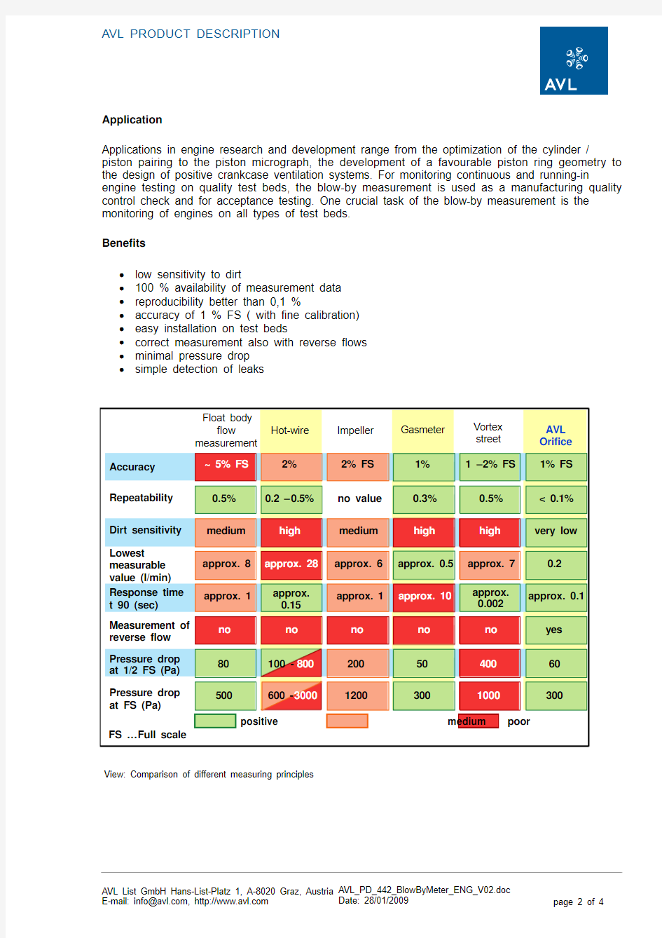
View: Comparison of different measuring principles
Technical Insight
The control and data evaluation unit is located in a
cabinet (splash- proof, IP 55) which is directly
connected with the orifice measuring pipe. The
measurement pipe as well as the control and data
evaluation unit are mounted on one console. The
device can easily be connected by analogue or serial (
RS232C) ports to the test bed system, whereby the
range of the blow-by amount is shown on the test bed
computer or an alternative remote indication (optional).
View: AVL Blow By Meter with two steadying vessels,
installed on a mounting plate
The AVL Blow By Meter determines the flow rate using
the orifice measurement principle.
A differential pressure transducer measures the
different gas pressures in front of and after the orifice
and the volume of gas flowing through the orifice can be
calculated from this difference.
Following areas of measurement are available:
measurement range : 0,2
to 10 l/min 1,5
to 75 l/min
3 to 150 l/min
6 to 300 l/min
12 to 600 l/min
24 to 1200 l/min
48 to 2400 l/min
View: Different orifices
Orifice principle
Technical Data
Measuring range : 0.2…2400 l/min (different orifice pipes)
Accuracy: better than ± 1 % FS with optional fine linearization
better than ± 1,5 % FS standard linearization
Outlets: analogue ± 10 V matching ± 100 % FS
RS232C conforming to AK generic communication protocol Power supply: 24 V DC
Power consumption: 35 W
Protection class: IP 55
Temperature range: -10...55 °C
Dimension 3...150 l/min: approx. 330 x 350 x 75 mm (w x h x d)
Scope of Supply
Each consisting of:
1 Orifice measuring pipe
1 Electronics
2 Measurement tube clamps
1 Power supply cable (24 V DC), length 15m
1 Signal cable, length 15m
1 Cable BBY RS232, length 15m
1 Operating manual 442
Options/Extensions
The AVL Blow By Meter can be expanded with following accessories:
?different orifice measuring pipes
?appropriate steadying vessels
?orifice heating
?different remote indications
?absolute pressure sensor for the crank case
?negative pressure application
?AVL function tester