AP438中文资料
PWM Fan Speed Controller
Features
- Built-in 30Khz OSC provide 0%~100% PWM output
- Over Temperature Protector(OTP) flag. (AP439 only).
- Open collect output(OTP & PWM pins). - SIP-4L package for AP438.
- SIP-5L, SOP-8L package for AP439.
Applications
- PC Power. - DC Fan
General Descriptions
The AP438/9 series’s PWM output has built-in NPN power transistor that controls the Fan current & Fan speed. AP439 built-in over temperature alarm flag.
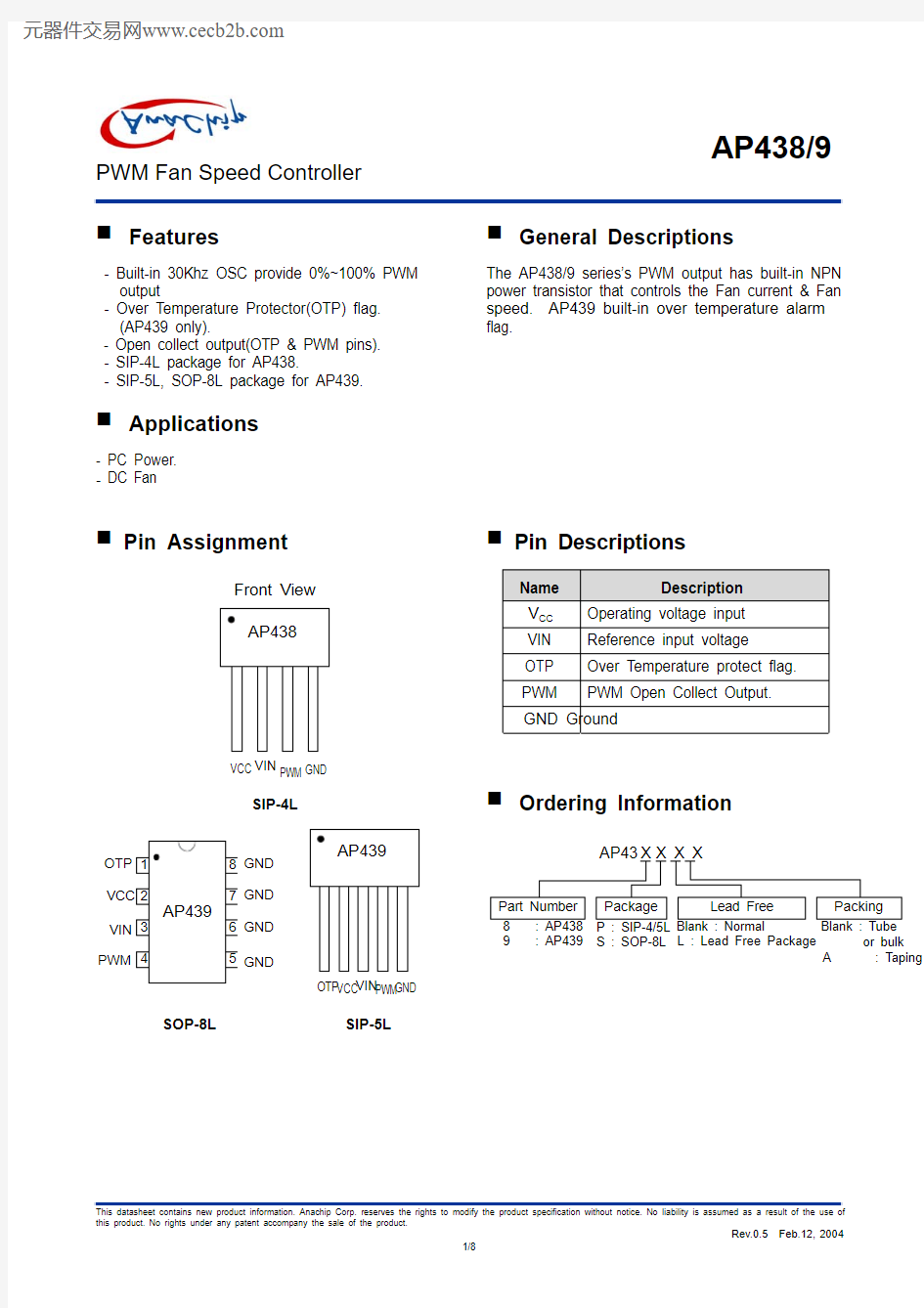
Pin Assignment
VCC
VIN Front View GND
PWM
VIN
SOP-8L SIP-5L
SIP-4L
GND
OTP GND VIN GND
GND
PWM
Pin Descriptions
Name Description
V CC Operating voltage input VIN Reference input voltage OTP Over Temperature protect flag. PWM PWM Open Collect Output.
GND Ground
Ordering Information
S : SOP-8L 9 : AP439
L : Lead Free Package
or bulk
A : Taping
PWM Fan Speed Controller
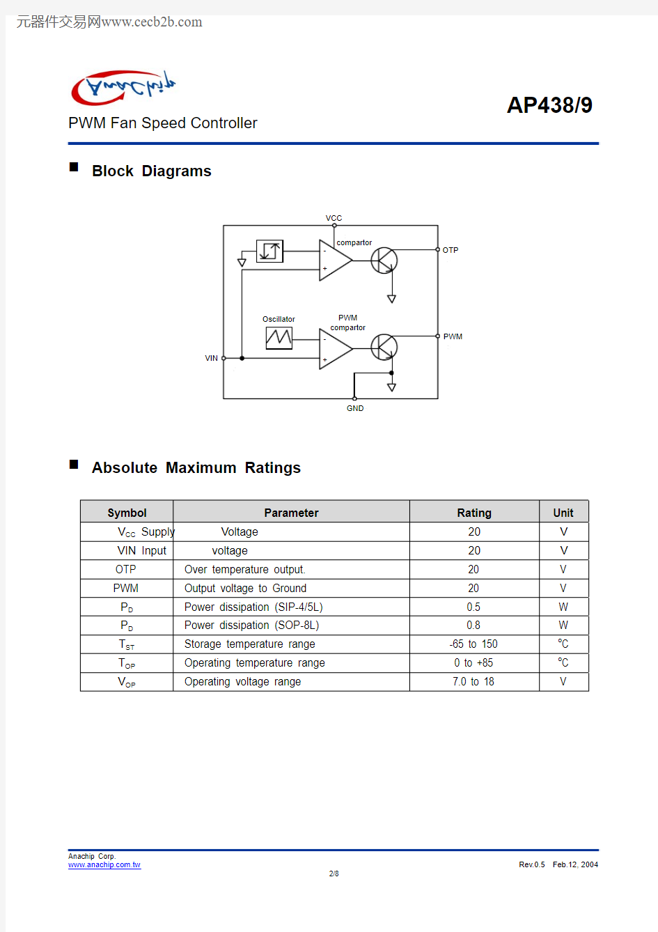
Block Diagrams
OTP
PWM
VIN
GND
Absolute Maximum Ratings
Symbol Parameter Rating Unit
Voltage 20 V V CC Supply
VIN Input
voltage 20 V OTP Over temperature output. 20 V
PWM Output voltage to Ground 20 V
P D Power dissipation (SIP-4/5L) 0.5 W
P D Power dissipation (SOP-8L) 0.8 W
T ST Storage temperature range -65 to 150 o C
T OP Operating temperature range 0 to +85 o C
V OP Operating voltage range 7.0 to 18 V
PWM Fan Speed Controller
Electrical Characteristics
Unless otherwise specified, guaranteed for Tj=25O
C , V CC =12V .
Symbol Parameter Conditions Min. Typ. Max. Units
V CC Supply Voltage 7.0 - 18
V I IN Input Bias Current(V IN Pin) V IN =
2.0V, 0.5 2 7 uA V IN Input Voltage Range 0 VCC-0.5 V DUTY PWM duty cycle range 0 100 % V IN(OTP) OTP Detect Voltage
3.3 3.4 3.5 V V IN(Release) OTP release Voltage 2.65 2.75 2.85 V V IN(HS) OTP detect Voltage Hysteresis 450 650 850 mV V IN(PWM0) Max Input voltage of 0% PWM 0.75 0.8 0.85 V V IN(PWM100) Min Input voltage of 100% PWM 2.80 2.85 2.90 V
I S Supply Current Output floating 2.5 mA
V PWM(ON) PWM transistor ON voltage
I PWM =500mA
continued
1.1 1.3 V I PWM Max. sink current 500 mA V OTP(L) OTP low level voltage I OTP =20mA 0.3 0.6 V I OTP
Max. sink current
20 mA F OSC OSC Frequency
0O C Application Circuit PWM Fan Speed Controller Typical Characteristics PWM Fan Speed Controller Marking Information (1) SIP4/5L (2) SOP-8L SOP-8L ( Top View ) Logo ~ Part Number PWM Fan Speed Controller Package Information (1) Package Type: SIP-4L ( unit: mm / [inch] ) 0.004] 0.1 3.65±±0.001] 0.03±±0.03±0.001] ±0.001] [0.150±1.27[0.0500.11.42±[0.056±0.001] [0.015± 1.25±0.049] ±1.03±[0.041±0.11.55±° °7~°30.1±0.004] ± PWM Fan Speed Controller Package Information (Continued) (2) Package Type: SIP-5L ( unit: mm / [inch] ) 0.001] [0.0150.030.38±±0.001] [0.0370.030.95±±[0.1440.13.65±±0.003] [0.0190.10.48±± 0.001] [0.015±° °3~[0.5630.314.3±±[0.0610.11.55±±0.003]0.1±±°5~2° °3~2 PWM Fan Speed Controller Package Information (Continued) (3) Package Type: SOP-8L Dimensions In Millimeters Dimensions In Inches Symbol Min. Nom. Max. Min. Nom. Max. A 1.40 1.60 1.75 0.055 0.063 0.069 A1 0.10 - 0.25 0.040 - 0.100 A2 1.30 1.45 1.50 0.051 0.057 0.059 B 0.33 0.41 0.51 0.013 0.016 0.020 0.008 0.010 C 0.19 0.20 0.25 0.0075 D 4.80 5.05 5.30 0.189 0.199 0.209 E 3.70 3.90 4.10 0.146 0.154 0.161 e - 1.27 - - 0.050 - H 5.79 5.99 6.20 0.228 0.236 0.244 L 0.38 0.71 1.27 0.015 0.028 0.050 y - - 0.10 - - 0.004 θ0O - 8O0O - 8O