KBP005M中文资料
KBP005M thru KBP10M, 3N246 thru 3N252
Document Number 8853103-Dec-04
Vishay Semiconductors
https://www.360docs.net/doc/bd16828438.html,
1
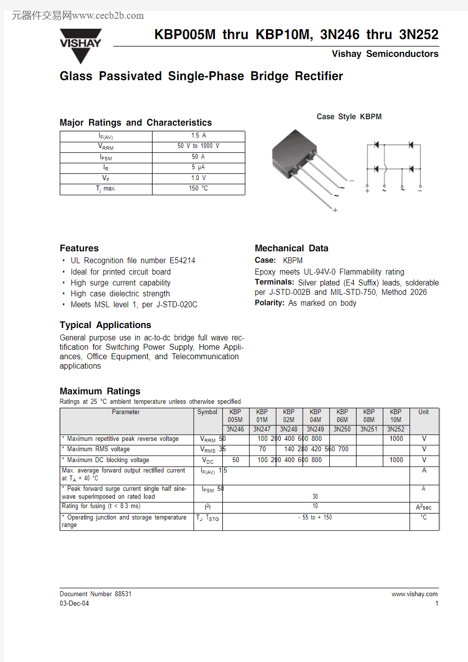
Glass Passivated Single-Phase Bridge Rectifier
Major Ratings and Characteristics
I F(AV) 1.5 A V RRM 50 V to 1000 V
I FSM 50 A I R 5 μA V F 1.0 V T j max.
150 °C
Features
?UL Recognition file number E54214 ?Ideal for printed circuit board ?High surge current capability ?High case dielectric strength
?
Meets MSL level 1, per J-STD-020C
Typical Applications
General purpose use in ac-to-dc bridge full wave rec-tification for Switching Power Supply, Home Appli-ances, Office Equipment, and Telecommunication applications
Mechanical Data
Case: KBPM
Epoxy meets UL-94V-0 Flammability rating
Terminals: Silver plated (E4 Suffix) leads, solderable per J-STD-002B and MIL-STD-750, Method 2026Polarity: As marked on body
Maximum Ratings
Ratings at 25 °C ambient temperature unless otherwise specified.
Parameter
Symbol
KBP 005M KBP 01M KBP 02M KBP 04M KBP 06M KBP 08M KBP 10M Unit
3N246
3N247
3N248
3N249
3N250
3N251
3N252
* Maximum repetitive peak reverse voltage V RRM 50 100 200 400 600 800
1000 V * Maximum RMS voltage V RMS 35 70 140 280 420 560 700 V * Maximum DC blocking voltage
V DC 50 100 200 400 600 800 1000 V
Max. average forward output rectified current at T A = 40 °C
I F(AV) 1.5 A * Peak forward surge current single half sine-wave superimposed on rated load I FSM 50 30 A
Rating for fusing (t < 8.3 ms)
I 2t 10 A 2sec * Operating junction and storage temperature range
T J , T STG
- 55 to + 150
°C
https://www.360docs.net/doc/bd16828438.html, 2
Document Number 88531
03-Dec-04
KBP005M thru KBP10M, 3N246 thru 3N252
Vishay Semiconductors
Electrical Characteristics
Ratings at 25 °C ambient temperature unless otherwise specified.
Thermal Characteristics
Ratings at 25 °C ambient temperature unless otherwise specified.
Notes:
(1) Thermal resistance from junction to ambient and from junction to lead mounted on P.C.B. with, 0.47 x 0.47" (12 x12 mm) copper pads. * JEDEC registered values
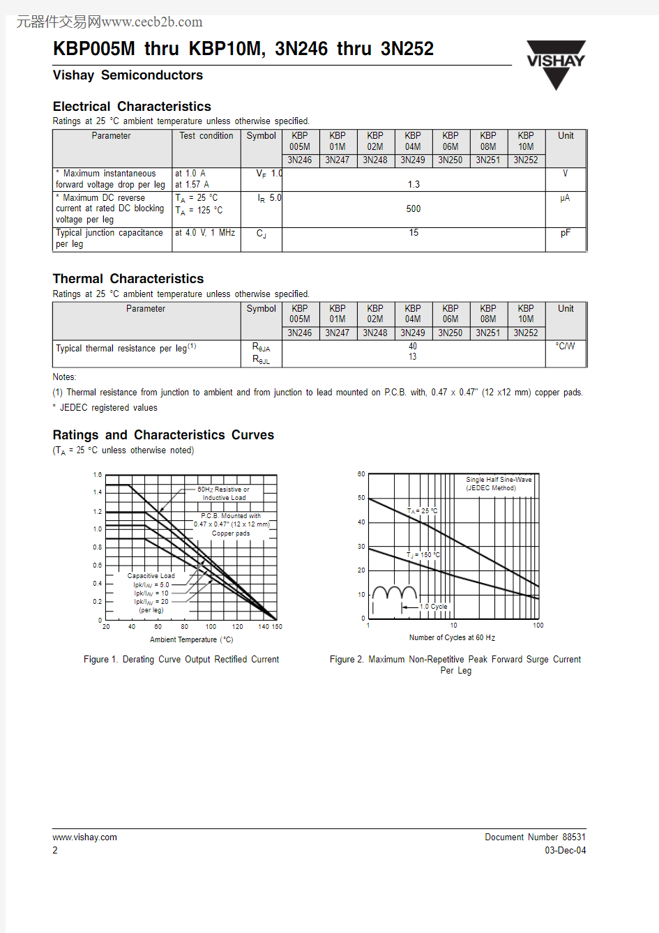
Ratings and Characteristics Curves
(T A = 25 °C unless otherwise noted)
Parameter
T est condition
Symbol
KBP 005M KBP 01M KBP 02M KBP 04M KBP 06M KBP 08M KBP 10M Unit
3N246
3N247
3N248
3N249
3N250
3N251
3N252
* Maximum instantaneous forward voltage drop per leg
at 1.0 A at 1.57 A
V F 1.0
1.3V * Maximum DC reverse
current at rated DC blocking voltage per leg
T A = 25 °C T A = 125 °C I R 5.0
500μA Typical junction capacitance per leg
at 4.0 V , 1 MHz C J
15
pF
Parameter
Symbol
KBP 005M KBP 01M KBP 02M KBP 04M KBP 06M KBP 08M KBP 10M Unit
3N246
3N247
3N248
3N249 3N250
3N251
3N252
Typical thermal resistance per leg (1) R θJA R θJL
40 13
°C/W Figure 1. Derating Curve Output Rectified Current
Figure 2. Maximum Non-Repetitive Peak Forward Surge Current
Per Leg
KBP005M thru KBP10M, 3N246 thru 3N252
Document Number 8853103-Dec-04
Vishay Semiconductors
https://www.360docs.net/doc/bd16828438.html,
3
Package outline dimensions in inches (millimeters)
Figure 4. Typical Reverse Leakage Characteristics Per Leg