TL431数据手册
UNISONIC TECHNOLOGIES CO., LTD
TL431
LINEAR INTEGRATED CIRCUIT
PROGRAMMABLE PRECISION REFERENCE
DESCRIPTION
The UTC TL431 is a three-terminal adjustable regulator with a guaranteed thermal stability over applicable temperature ranges. The output voltage may be set to any value between V REF (approximately 2.5V) and 36V with two external resistors. It provides very wide applications, including shunt regulator, series regulator, switching regulator, voltage reference and others.
FEATURES
* Programmable output Voltage to 36V. * Low dynamic output impedance 0.2?. * Sink current capability of 1.0 to 100mA.
* Equivalent full-range temperature coefficient of 50ppm/ °C
typical for operation over full rated operating temperature range.
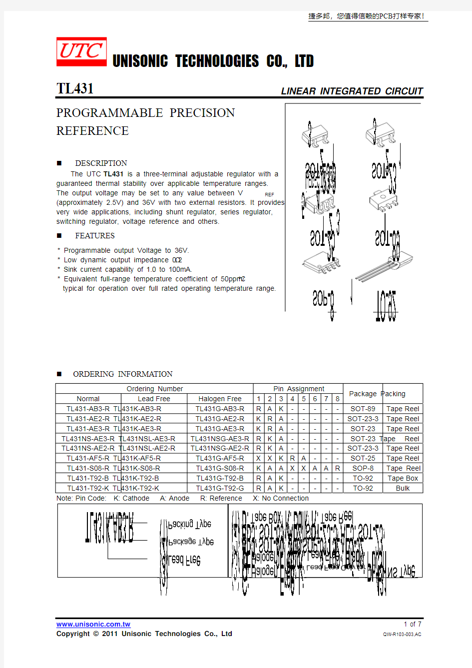
ORDERING INFORMATION
Ordering Number Pin Assignment
Normal Lead Free Halogen Free 12345678 Package Packing
TL431-AB3-R TL431K-AB3-R TL431G-AB3-R R A K ----- SOT-89 Tape Reel TL431-AE2-R TL431K-AE2-R TL431G-AE2-R K R A ----- SOT-23-3 Tape Reel TL431-AE3-R TL431K-AE3-R TL431G-AE3-R K R A ----- SOT-23 Tape Reel TL431NS-AE3-R TL431NSL-AE3-R TL431NSG-AE3-R R K A ----- SOT-23 Tape Reel TL431NS-AE2-R TL431NSL-AE2-R TL431NSG-AE2-R R K A ----- SOT-23-3 Tape Reel TL431-AF5-R TL431K-AF5-R TL431G-AF5-R X X K R A --- SOT-25 Tape Reel TL431-S08-R TL431K-S08-R TL431G-S08-R K A A X X A A R SOP-8 Tape Reel TL431-T92-B TL431K-T92-B TL431G-T92-B R A K ----- TO-92 Tape
Box TL431-T92-K TL431K-T92-K TL431G-T92-G R A K ----- TO-92 Bulk
捷多邦,您值得信赖的PCB打样专家!
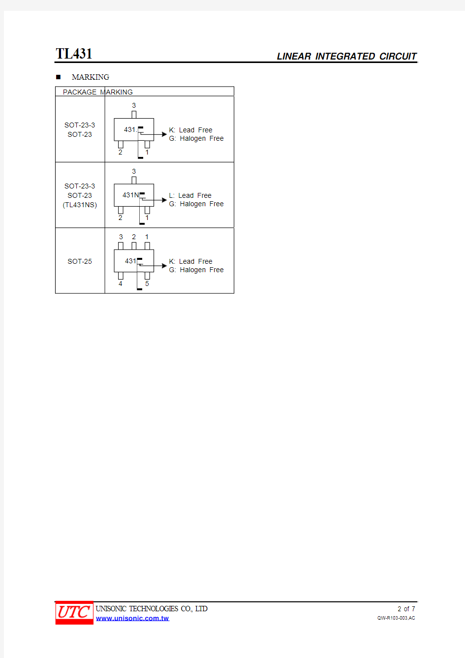
MARKING
431.
431N
431
BLOCK DIAGRAM
CATHODE (K)
ANODE(A)
REFERENCE (R)
ABSOLUTE MAXIMUM RATINGS (Operating temperature range applies unless otherwise specified)
PARAMETER SYMBOL RATINGS UNIT
Cathode Voltage V KA 37 V Cathode Current Range(Continuous) I KA -100 ~ +150 mA Reference Input Current Range I REF -0.05 ~ +10 mA
TO-92 770 mW
SOT-89 800 mW
Power Dissipation SOT-23/SOT-23-3/SOT-25P D 300 mW
Operating Junction T J +150 °C Operating Ambient T OPR -40 ~ +85 °C Storage Temperature T STG -65 ~ +150 °C
Note: Absolute maximum ratings are those values beyond which the device could be permanently damaged
Absolute maximum ratings are stress ratings only and functional device operation is not implied.
RECOMMENDED OPERATING CONDITIONS
PARAMETER SYMBOL MIN TYP MAX UNIT
Cathode Voltage V KA V REF 36 V Cathode Current I KA 1 100 mA
ELECTRICAL CHARACTERISTICS (T C = 25°C, unless otherwise specified.)
TEST CIRCUIT
V KA
V KA=V REF×(1+R1/R2)+I REF×
R1
For V KA
=V REF
For V KA≥V REF For I KA(OFF)
APPLICATION CIRCUIT
V OUT=(1+R1/R2)×V REF
V OUT=(1+R1/R2)×V REF
Minimum V OUT=V REF+5V V OUT=(1+R1/R2)×V REF
Shutdown Regulator Output Control of a Three
-Terminal Fixed Regulator
Higher-current Shunt Regulator
I OUT=V REF/R S I OUT =V REF/R CL
Constant-current Sink Current Limiting or Current Source
■ TYPICAL CHARACTERISTICS
-11023
400
200
600
800
-2Cathode Voltage (V)
C a t h o d e C u r r e n t (μA
)
1
2
3
4
5
6
7
01234567
Time (μs)
I n p u t a n d O u t p u t V o l t a g e (V )
Pulse Response
C h a n g
e
I n R e f e
r e n
c e I n p u t V o l t a g e (m V )
Change in Reference Input Voltage vs.
Cathode Current vs. Cathode Voltage
0510********
3540
-1-1
Cathode Voltage (V)
-2
-1
1
2
3
-75-50-250255075100125Cathode Voltage (V)C a t h o d e C u r r e n t (m A )
Cathode Current vs. Cathode Voltage
150
-5-10-15-20-25-30-35-40
Frequency, f (Hz)
020
40
60Frequency Response
1K
10K
100K
1M
10M
10
3050-40-20
2550100125150750.8
1.6
2.4
3.0Temperature, ()
Deviation of Reference Voltage