UR132-26-AF5-5-R中文资料

UNISONIC TECHNOLOGIES CO., LTD
UR132 LINEAR INTEGRATED CIRCUIT
200mA LOW DROPOUT LINEAR VOLTAGE REGULATOR
DESCRIPTION
The UTC UR132 is a 200mA fixed output voltage low dropout linear regulator. Wide range of available output voltage fits most of applications. Built-in output current-limiting most thermal-limiting provide maximal protection against any fault conditions.
FEATURES
* Guaranteed 200mA output current * Input voltage range up to 12V * Extremely tight load regulation * Fast transient response
* Current-limiting and thermal-limiting
* Three-terminal adjustable or fixed voltage.
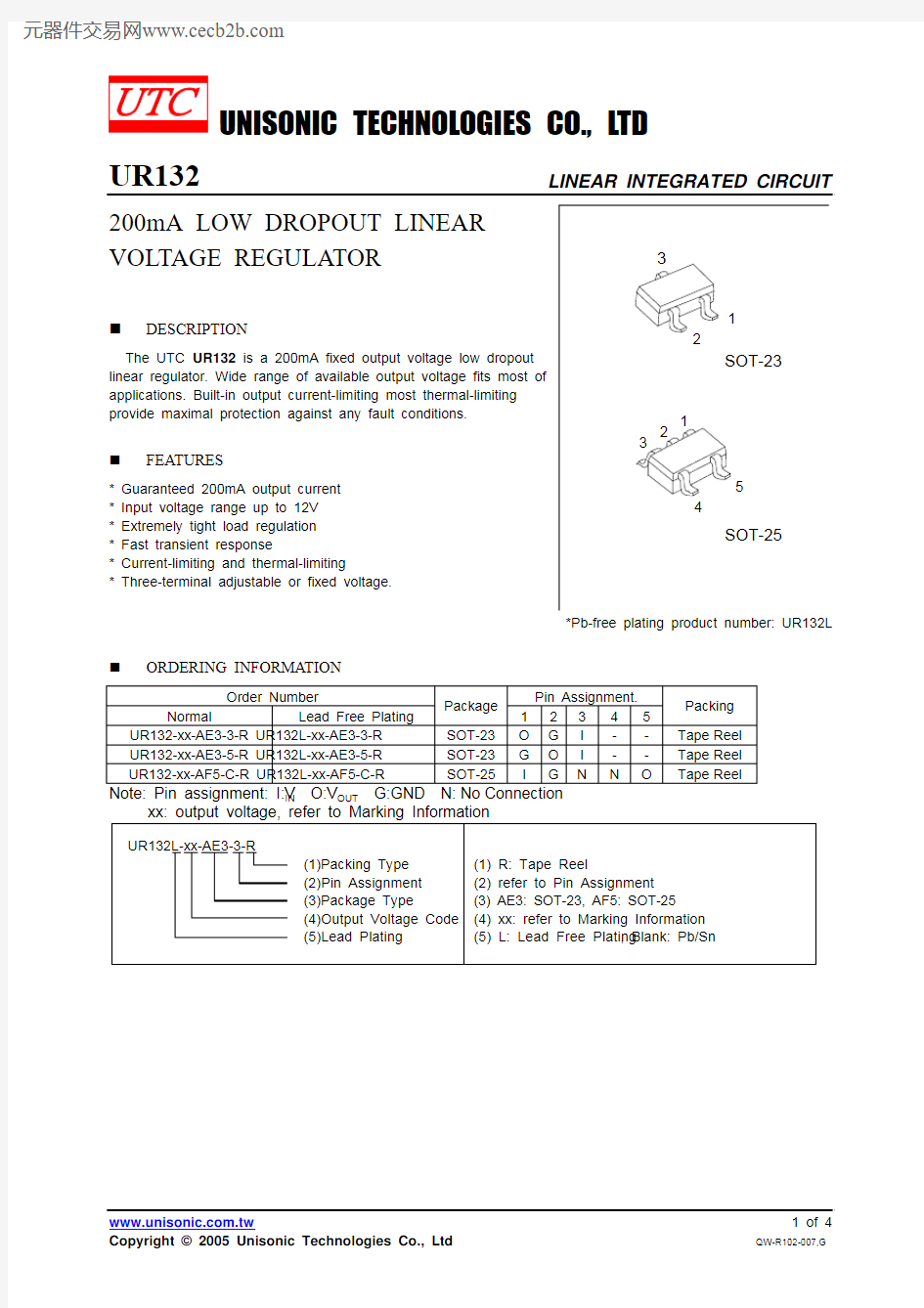
*Pb-free plating product number: UR132L
ORDERING INFORMATION
Order Number
Pin Assignment.
Normal Lead Free Plating
Package
12345
Packing UR132-xx-AE3-3-R UR132L-xx-AE3-3-R SOT-23O G I --Tape Reel
UR132-xx-AE3-5-R UR132L-xx-AE3-5-R SOT-23G O I --Tape Reel UR132-xx-AF5-C-R UR132L-xx-AF5-C-R SOT-25
I G N N O
Tape Reel
Note: Pin assignment: I:V IN O:V OUT G:GND N: No Connection
MARKING INFORMATION
BLOCK DIAGRAM
V OUT
V IN
ABSOLUTE MAXIMUM RATINGS
PARAMETER SYMBOL RATING UNIT
Input Voltage V IN -0.3~12 V Power Dissipation P D 300 mW Junction Temperature T J +125 °C Operation Temperature T OPR -20~+125 °C Storage Temperature T STG -40~+150 °C
Note: 1.Absolute maximum ratings are those values beyond which the device could be permanently damaged.
Absolute maximum ratings are stress ratings only and functional device operation is not implied.
2.The device is guaranteed to meet performance specification within 0 ~ +70 operating temperature range and assured by design from -20 ~ +125 .
ELECTRICAL CHARACTERISTICS (Ta=25°C, C IN =1μF, C OUT =10μF, unless otherwise specified)
FOR V OUT <3.3V (V OUT ±2%)
PARAMETER SYMBOL TEST CONDITIONS MIN TYP. MAX UNIT
Output Voltage V OUT I L =2mA, V IN -V OUT =
2V V OUT ×0.98 V OUT V OUT ×1.02V
Output Voltage Temperature Coefficient T C V O 50 150 PPM/°C
Line Regulation
△V OUT I L =2mA,
V IN -V OUT =2V~V IN =9V 0.5 %V OUT Load Regulation (note 2)
△V OUT I L =2mA~200mA,
V IN -V OUT =2V 10 30 mV Current Limit (note 3) I L V IN -V OUT =2V, V OUT =0V 300 mA
Dropout Voltage (note 4,5) V D 1.5 V
Standby current I STN-BY I L =0, V IN =9V 3.0 mA
FOR ADJ and V OUT ≧3.3V (V OUT ±2%)
PARAMETER SYMBOL TEST CONDITIONS MIN TYP. MAX UNIT
Output Voltage V OUT I L =2mA, V IN -V OUT =
2V V OUT ×0.98 V OUT V OUT ×1.02V Adjustable (R1=120?,R2=200?,V OUT =3.3V) Reference Voltage V REF V IN -V OUT =2V, I L =
2mA 1.238 1.250 1.262 V Output Voltage Temperature Coefficient T C V O 50 150 PPM/°C
Line Regulation
△V OUT I L =2mA,
V IN -V OUT =2V~V IN =12V 0.5 %V OUT Load Regulation (note 2)
△V OUT I L =2mA~200mA,
V IN -V OUT =2V
10 30 mV Current Limit (note 3) I L V IN -V OUT =2V, V OUT =
0V 300 mA Dropout Voltage (note 4,5) V D 1.3 V Standby current I STN-BY I L =0, V IN =12V 5.0 mA Note 1: Guaranteed by design.
Note 2: Regulation is measured at constant junction temperature, using pulsed on time. Note 3: Current limit is measured at constant junction temperature, using pulsed on time.
Note 4: Dropout is measured at constant junction temperature, using pulsed on time, and the criterion is V OUT inside
target value ±2%.
Note 5: Dropout test is skipped at the condition of V IN <3V.
TYPICAL APPLICATION CIRCUIT
The part may oscillate without the capacitor, a 10μF (or larger) capacitor is recommended between V OUT and GND for stability. Any type of capacitor can be used, but not Aluminum electrolytic when operating below -20°C. The capacitance may be increased without limit. Besides, another 1μF capacitor (or larger) should be placed between V IN to GND.
UR132 ADJUSTABLE
V OUT
V IN
Cr:10uF to improve ripple rejection V OUT =V REF (1+R2/R1)+I ADJ *R2