Decentralized Nonlinear Control of Wind Turbine
IEEE TRANSACTIONS ON POWER SYSTEMS, VOL. 23, NO. 2, MAY 2008
613
Decentralized Nonlinear Control of Wind Turbine With Doubly Fed Induction Generator
Feng Wu, Xiao-Ping Zhang, Senior Member, IEEE, Ping Ju, Member, IEEE, and Michael J. H. Sterling
Abstract—In this paper, a novel nonlinear control design method for the wind turbine (WT) with doubly fed induction generator (DFIG) using differential geometry theory is proposed. The WT with DFIG is represented by a third-order model where electromagnetic transients of the stator are neglected. Then the model is exactly linearized using the coordinate transformation in differential geometry theory. Since the relative degree of the model of the WT with DFIG is equal to the order of the original system model, the linearized model can be transformed into the Bronovsky norm form. The linear quadratic regulator (LQR) design method is introduced to design the optimal control for the linearized system, and the nonlinear control for the WT with DFIG obtained by the inverse coordinate transformation only depends on the parameters of the WT with DFIG. Hence, the nonlinear control can be considered as a decentralized control, which is a desirable feature for a WT with DFIG. To illustrate the effectiveness of the nonlinear controller proposed, simulations on a single machine in?nite bus (SMIB) system and a four-machine system are performed. Compared to the conventional PI control, the proposed nonlinear control can improve the transient stability of the power systems and enhance the system damping. Index Terms—Control systems, differential geometry, doubly fed induction generator, nonlinear systems, transient stability, wind power generation.
I. INTRODUCTION
W
ITH the growing integration of wind energy into power grids, the impact of wind generators on power system stability, especially in the aspect of transient stability, is of increasing concern. In the development of wind turbine (WT) techniques, WT with doubly fed induction generator (DFIG) is becoming the dominant type of WT system used in wind farms [1], because it has the characteristics of low investment and ?exible control. A decoupling control technique for the active power and reactive power proposed in [2] has been widely used in control of the WT with DFIG [3]–[5]. The decoupling control technique was based on conventional PID controllers. PID controllers are well accepted in the engineering ?eld for their reliability and simplicity. With these features, the PID control has been widely used in excitation control and steam valve control of power systems. However, the parameters of the PID controllers are usually tuned with the approximately linearized model. In this situation,
Manuscript received June 12, 2007; revised October 14, 2007. Paper no. TPWRS-00433-2007. F. Wu, X.-P. Zhang, and M. J. H. Sterling are with the Department of Electronic, Electrical, and Computer Engineering, University of Birmingham, Birmingham B15 2TT, U.K. (e-mail: wfcn77@https://www.360docs.net/doc/d614387090.html,; X.P.Zhang@bham.ac. uk). P. Ju is with the College of Electrical Engineering, HoHai University, Nanjing 210098, China (e-mail: pju@https://www.360docs.net/doc/d614387090.html,). Digital Object Identi?er 10.1109/TPWRS.2008.920073
the dynamic control performance may not be guaranteed during the transients of the WT with DFIG, especially under large disturbances in power systems. Hence, new methods for the design of controllers for the WT with DFIG system should be investigated in order to achieve better control performance in terms of transient stability of power systems. Differential geometry is a branch of mathematics that studies the geometry of curves, surfaces, and manifolds. During the past decades, differential geometry has been proven to be successful in the study of the nonlinear system. Based on the branch of the exact linearization via feedback, the nonlinear control design method using differential geometry theory has been developed [6], [7]. In the design, the model of the system to be controlled is exactly linearized by coordinate transformation using differential geometry theory. Then the optimal control law is obtained for the linearized system using linear optimal control principles. Finally the nonlinear control law is derived from the linear optimal control law by inverse coordinate transformation using differential geometry theory. In the past, nonlinear control design methods using differential geometry theory have been used in power system stability control problems. A nonlinear control design method using differential geometry theory has been applied successfully in excitation control design of synchronous generators for multimachine systems [8] where both small signal stability and transient stability of the power systems were improved. A nonlinear rocontrol apbust control based on the combination of the proach and the exact linearization approach using differential geometry theory has been presented in [9] for excitation control of synchronous generators. The robustness of the controller to the uncertainty of the network structure and parameters, and to the disturbance was improved, and the transient stability control of power systems was enhanced. A nonlinear coordinated control of excitation and governor systems for a hydraulic power plant using differential geometry theory has been proposed in [10], and better performances of the hydraulic generator under large disturbance were achieved. A nonlinear control design method using differential geometry theory has been used in the dc link voltage control of PWM ac/dc converters [11] where the dc voltage was regulated effectively. A nonlinear control for PWM back to back converters using differential geometry theory, which incorporates the power balance of the input and output of the converters, the current transients of the load, has been proposed in [12] while the dynamics of mechanical motion of the load were not considered. The responses of the voltage to the load change were improved and the capacitance of the dc electrolytic capacitor was considerably reduced. The control objective in both [11] and [12] was to regulate the dc voltage. A feedback control
0885-8950/$25.00 ? 2008 IEEE
Authorized licensed use limited to: Tsinghua University Library. Downloaded on April 26,2010 at 02:55:41 UTC from IEEE Xplore. Restrictions apply.
614
IEEE TRANSACTIONS ON POWER SYSTEMS, VOL. 23, NO. 2, MAY 2008
Dynamic Equations: (1)
(2)
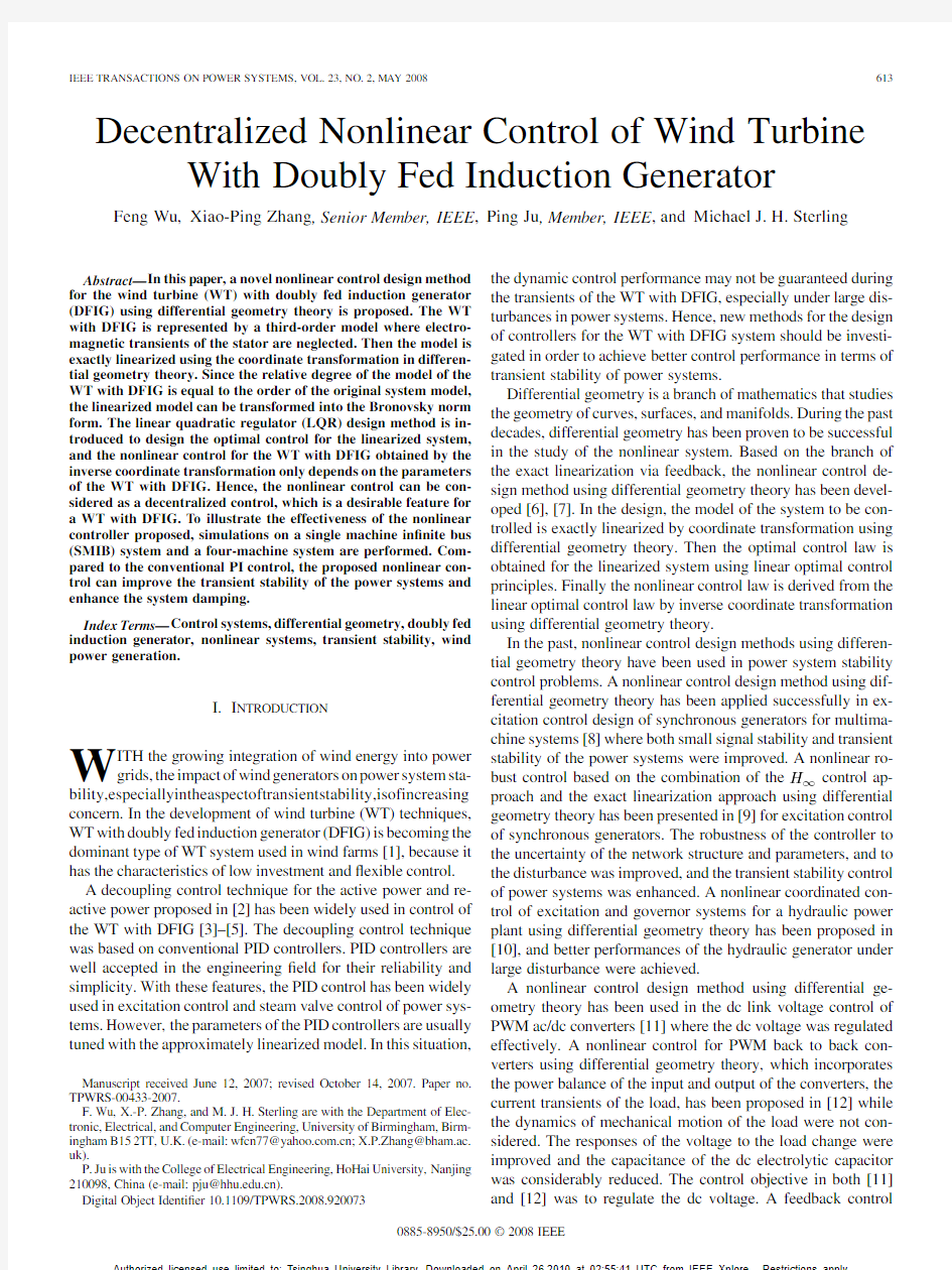
Fig. 1. Equivalent circuit of DFIG.
(3) technique using differential geometry theory has been proposed in the control of the full scale back to back converters of a synchronous generator based wind generation system [13] while the electromechanical dynamics of the wind generation system have not been considered. The control objective in [13] was to improve the fault-ride through ability of the wind generation system. With the continuous integration of wind generation systems into power systems, it will be of great importance to propose novel control methods in improving the transient stability of power systems. As far as we know, transient stability control of power systems with the electromechanical dynamics of wind generation systems using differential geometry theory has not been investigated yet. In this paper, a nonlinear control method for a WT with DFIG using differential geometry theory will be investigated in the transient stability control of power systems where the electromechanical dynamics of DFIG are considered. Transient stability control performance of the nonlinear control will be examined in terms of critical clearing time (CCT). The paper is arranged as follows. In Section II, a third-order model of the WT with DFIG for stability studies is presented at ?rst. A nonlinear control design method using differential geometry theory is introduced in Section III, and then in Section IV, the method is applied to the control of the WT with DFIG where the WT with DFIG is integrated into the power system. Based on the relative degree analysis, the nonlinear model of the DFIG is exactly linearized, and the linear optimal control design method is applied to obtain the control law. In Section V, simulations are performed on a single machine in?nite bus system (SMIB) and a four-machine system to verify the effectiveness of the proposed nonlinear controller for the WT with DFIG in the transient stability control, while conclusions are drawn in Section VI. where
Electrical Equations: (4) (5) (6) (7) where is the rotor slip; is the total inertia constant of the is the output active power of the turbine and the generator; stator of the DFIG; is the mechanical power of the WT; is the stator self-inductance; is the rotor self-inductance; is the mutual inductance; is the synchronous angle speed; is the stator reactance; is the stator leakage reactance; is the rotor leakage reactance; is the stator transient reactance; and are the and axis voltages behind the transient is the rotor circuit time constant; reactance, respectively; and are the and axis stator currents, respectively; and are the and axis stator terminal voltages, respectively; and are the and axis rotor voltages, respectively; is the reactive power of the stator of the DFIG. Equation (1)–(3) shows the third-order DFIG model and the voltage equations and the ?ux linkage equations of the DFIG are based on the motor convention. In the case of transient stability studies, it is common to reduce the ?fth-order model to such a third-order model [17], [18]. From (2) and (3), the model of the WT with DFIG is a system reference frame. The inputs are with two inputs in the and , respectively. III. NONLINEAR CONTROL DESIGN METHOD A. Exact Linearization In the conventional linear control design method, the model of the nonlinear system is linearized near a chosen operating point using the ?rst-order Taylor’s series approximation. The accuracy of the approximate linearized model is acceptable only when the system is operating near the point chosen during design. Under large disturbances, the system operating point may be far away from the design point chosen. In this situation,
II. MODEL OF WT WITH DFIG The WT system consists of a drive train and DFIG. The drive train of the WT system is represented with a one-mass model [14], while the DFIG is modeled by a second order model where the electromagnetic transients of the stator are neglected [15]–[18]. The equivalent circuit of DFIG is shown in Fig. 1. Hence, the model of the WT with DFIG used in this paper is a third-order model as follows:
Authorized licensed use limited to: Tsinghua University Library. Downloaded on April 26,2010 at 02:55:41 UTC from IEEE Xplore. Restrictions apply.
WU et al.: DECENTRALIZED NONLINEAR CONTROL OF WIND TURBINE WITH DOUBLY FED INDUCTION GENERATOR
615
the control capability of PID controllers may be greatly weakened in terms of large disturbance transient stability control. The exact linearization method linearizes the nonlinear model in the global state space or in a large enough region of state space by choosing suitable coordinate transformation. Designing the nonlinear controller based on the exact linearized model, the robust control performance can be guaranteed at any point where the system would operate. In order to simplify the introduction, without loss of generality, a system with two inputs and two outputs is taken as an example to illustrate the principle of the exact linearization. The two inputs and two outputs system can be written as
is a nonlinear vector function, which new state variables; is called a diffeomorphism between two coordinate spaces, satis?es
(10) B. Nonlinear Control Design , When relative degrees of the nonlinear system, equals the order of the model , (9) can be transformed into the Bronovsky norm form as follows:
(8) is the vector of the state variables; is the order where , is the th of the nonlinear system; is the number of control variables or the control variable; output variables; and are the n-dimensional vector is the th output variable; ?elds in the state space; is the scalar function of . as in [7], the origChoosing the similar mapping inal system in (8) can be transformed into the following form: (11) From the th and th equations in (12), we have
(12) where we see the equation at the bottom of the page. With (10) and (12), the corresponding control for the original system can be derived as follows:
(13) where
(9) ( ) to where is the relative degree from output function the nonlinear system; is the relative degree from output function to the nonlinear system; denotes the Lie with respect to ; is the vector of the derivative of
Applying linear optimal principles [19] to the system described by (11), the linear optimal control law can be obtained as follows: (14)
Authorized licensed use limited to: Tsinghua University Library. Downloaded on April 26,2010 at 02:55:41 UTC from IEEE Xplore. Restrictions apply.
616
IEEE TRANSACTIONS ON POWER SYSTEMS, VOL. 23, NO. 2, MAY 2008
where is the optimal vector of the control variables for the is the optimal feedback gain matrix and linearized system; is given by
(15) can be found by solving the following Riccati algewhere braic equation:
It can be seen that the system (17) is a two-input two-output nonlinear system. The relative degree of the model of the WT with DFIG can be calculated as follows. For when when then For when .
(16) Substituting (14) into (13), the control law for the original system can be obtained. IV. NONLINEAR CONTROL DESIGN FOR THE WT WITH DFIG A. Model Exact Linearization of the WT With DFIG The model of WT with DFIG, (1)–(3), is written as a standard af?ne nonlinear system as follows:
then Hence, the relative degree of the model of the WT with DFIG, , is 3, which equals to the order of the model. Now we choose the mapping for the coordinate transformation as follows: (21a)
(21b) (21c) Since the mechanical dynamics of the WT system is much slower than the electromagnetic dynamics of the WT system, it is reasonable to assume that the input mechanical power is constant during the transients of the DFIG under a system disturbance. Applying the mapping relationships in (21), the model of the WT with DFIG can be exactly linearized as follows: (22a) (22b) (22c) Substituting (2) and (3) into (22), we have (23a)
(17) where
Choosing the output variables: (18) (19) where is the terminal voltage of the WT with DFIG; is the control reference of the terminal voltage of the WT with DFIG, and the control reference is normally chosen as 1 p.u. reference frame with the Aligning the axis of the becomes zero, while direction of the terminal voltage, is equal to the magnitude of the terminal voltage. Based on (6) and (19), we have (23c) (23b)
B. Nonlinear Control Design for the WT With DFIG Equation (23) can be written as (24a) (24b) (24c)
(20)
Authorized licensed use limited to: Tsinghua University Library. Downloaded on April 26,2010 at 02:55:41 UTC from IEEE Xplore. Restrictions apply.
WU et al.: DECENTRALIZED NONLINEAR CONTROL OF WIND TURBINE WITH DOUBLY FED INDUCTION GENERATOR
617
According to the linear quadratic regulator (LQR) method in the linear control theory [19], the optimal control law of the system shown in (24) can be obtained by
Fig. 2. Con?guration of the SMIB system.
(25) (26) are the optimal feedback gain coef?cients; where is the initial mechanical power, which equals to the active power output of the DFIG stator at the initial condition. From (25) and (26), it can be seen that the active power and the terminal voltage are controlled independently via and , respectively. Choosing the weighting matrix in the Riccati equation as identity matrix, the optimal feedback coef?cients can be ob. tained: Using (26), the nonlinear control law for the WT with DFIG is given by
V. DYNAMIC SIMULATIONS The nonlinear control law, as given in (27), was implemented in MATLAB while the parameters of the WT with DFIG is given in the Appendix. Simulations were performed on an SMIB system and a four-machine system to verify the effectiveness and control performances of the nonlinear controller in improving the transient stability, the system damping and the fault ride-through capability of the WT with DFIG. A. Simulations on SMIB System The con?guration of the SMIB system is illustrated in Fig. 2. The SMIB system consists of an in?nite bus, a wind farm (WF) and an induction motor (IM) load, the details can be found in SimPowerSystems of MATLAB v7.1. To make the comparison more accurately, particle swarm optimization was applied to optimize the parameters of the PI controllers of the WT with DFIG. The optimization aims to shift all the eigenvalues as far to the left of the left hand side of the complex plane as possible, so as to achieve better damping characteristic. The details of the optimization and the optimized parameters can be found in [20]. The speed of the wind in the WF is kept constant at 12 m/s. The WF comprises six WTs. A three phase ground fault with , and the ground resistance of 10 was applied at B2 at s. Under this disturbance, the the fault was cleared at terminal voltage of the WT with DFIG dropped to 0.8 p.u. The simulations were carried out to compare the damping of the WT with DFIG using the PI controller, optimized PI controller and nonlinear controller. The details about the PI controller can be found in the SimPowerSystems Demo of MATLAB v7.1. The dynamics of the active power, reactive power, terminal voltage and the dc link voltage of the WT with DFIG using the nonlinear controller, PI controllers and optimized PI controllers are illustrated in Fig. 3. It can be seen that applying the nonlinear control, the system is stable and the damping of the WT system has been improved. The oscillations of the terminal voltage decayed very quickly after the fault was cleared. The peak value of the dc link voltage is 1400 V, which is lower than 1450 V with the PI control used. The improvement is bene?cial to the operation of the converters since this will reduce the stress to the converters. During the transient process, the minimum active power of the WT with DFIG with the proposed nonlinear controller is 0 MW, while the minimum active power of the WT with DFIG using the MW where the WT absorbed conventional PI controller is the active power. This reveals that the WT with DFIG using the conventional PI controller may lead to a worse transient stability problem of the power system. It should also be pointed out that under the large disturbance, the terminal voltage decreased signi?cantly, the WT with DFIG generated more reactive power to
(27a)
(27b) From (27), it can be seen that the nonlinear control law is only related to its own parameters. Hence, the nonlinear control can be considered as a decentralized control, which is a desirable feature of the controller for a WT with DFIG. Under disturbances, the active power and the terminal voltage of the WT with DFIG system may deviate far from the normal and , operating values, which may cause the rotor voltage calculated by (27), exceed the voltage capacity of the feedback and should be limited. In this paper, converter. Hence, for the WT with DFIG, if the calculated rotor voltage exceeds and are scaled proportionally as follows: If the limit, , then set and . The relationship between the active powers of the rotor and stator of the DFIG is implicitly described by the electrical equations of the DFIG. The sum of the rotor reactive power, the stator reactive power and the reactive power exchange between the DFIG and the grid is balanced by the reactive power generated by the dc link. The nonlinear controller proposed in (27) is used to regulate the voltage injections of the rotor side converter to control the slip and the stator terminal voltage to their control settings. While the conventional PI controller is used to regulate the voltage injections of the grid side converter to control the voltage of the dc link and the reactive power exchange between the DFIG and the grid to their control settings.
Authorized licensed use limited to: Tsinghua University Library. Downloaded on April 26,2010 at 02:55:41 UTC from IEEE Xplore. Restrictions apply.
618
IEEE TRANSACTIONS ON POWER SYSTEMS, VOL. 23, NO. 2, MAY 2008
B. Fault Ride-Through Capability Analysis The drop in the terminal voltage of WT with DFIG is increasing with the decreasing of the ground resistance of the three phase to ground fault. Smaller is the ground resistance, larger is the drop in the terminal voltage, and the disturbance is more serious. In order to study the fault ride-through capability of the WT with DFIG with the optimized PI controller and the nonlinear controller, simulations were performed under the fault, which is as same as the fault used in Section V-A, with the ground resistance decreasing step by step. When the ground resistance of the fault was decreased to 2.3 , the WT with DFIG with the optimized PI controller was tripped because of the over-voltage in the dc link in the feed-back converters, while the WT with DFIG with the nonlinear controller can still operate and is kept connected with the power system. The dynamics of the WT with DFIG with the optimized PI control and the nonlinear control under the fault with ground resistance of 2.3 are shown in Fig. 4. It can been seen that under the disturbance, the terminal voltage of the dc link of the WT with DFIG using the optimized PI control increased quickly for the accumulation of the active power in the capacitor, and reached the maximum dc voltage limit of 1900 V, and subsequently the dc over-voltage protection was triggered to trip the WT while the output active power and reactive power of the WT with DFIG with the optimized PI controller dropped to zero. However, under the disturbance, the WT with DFIG with the nonlinear control generated more reactive power to support the terminal voltage so that the generator was able to output more active power, hence less active power accumulated in the capacitor and the dc power of the dc link did not reach the dc voltage limit. In this situation, the dc over-voltage was not trigged to trip the WT where the WT was able to recover to the initial equilibrium point. Hence, the WT with DIFG with nonlinear control kept the WT being connected with the grid and recovered to the initial operation point. The simulations were performed with the ground resistance decreased further. When the ground resistance decreased to 2.1 , the WT with DFIG with the nonlinear controller tripped from the power system. It can be concluded that the fault ride-through capability of the WT with DFIG can be improved with the nonlinear controller proposed. C. Simulations on Multimachine System The four-machine system used in the simulations is shown in Fig. 5. The system was divided into two areas, in each of which there were two machines. To investigate the impact of the WT with different controllers such as the optimized PI controller and nonlinear controller on the transient stability performance of the power system, the four-machine system was modi?ed by replacing generator G3 with a wind farm (WF), which is the same as the WF in Fig. 2. The power ?ow of the four-machine system is also shown in Fig. 5. The parameters of the generators, transformers and lines of the four-machine system can be found in SimPowerSystems of MATLAB v7.1. Case 1: A three phase to ground fault was applied at bus 7 . The CCT was calculated under different conditions at such as the original four-machine system, the modi?ed four-machine system with the WT using the PI control (PI), optimized PI
Fig. 3. Dynamics of the WT with DFIG.
restore the terminal voltage, and after the fault, the output reactive power of the WT with DFIG with the nonlinear controller was higher than the initial output. After the fault was cleared, the system became stable at a new equilibrium where the reactive power output at this point is higher than that at the initial equilibrium before the system fault. It can also be concluded that under the large disturbance the improvement in the damping of the WT with DFIG with the optimized PI controllers is not as large as that under the small disturbance [20]. For the convenience of demonstration, only WTs with the optimized PI controller and nonlinear controller are compared in the subsequently part of the paper.
Authorized licensed use limited to: Tsinghua University Library. Downloaded on April 26,2010 at 02:55:41 UTC from IEEE Xplore. Restrictions apply.
WU et al.: DECENTRALIZED NONLINEAR CONTROL OF WIND TURBINE WITH DOUBLY FED INDUCTION GENERATOR
619
TABLE I CCT OF THE SIMULATED SYSTEM UNDER DIFFERENT CONDITIONS
From Table I, it can be seen that in comparison to the original four-machine system, the multimachine system with the WT with DFIG using either the PI controller, or the optimized PI control, or the nonlinear controller can actually enhance the transient stability margin of the system in terms of CCT. Furthermore, for the four-machine systems with the WT with DFIG, the CCT using the nonlinear controller is higher than those using the PI controller and the optimized PI controller. The transient stability control bene?t of the four-machine system with the WT using the nonlinear controller is signi?cant. Case 2: A three phase to ground fault was applied in the middle of the transmission line 1 at , and the fault was cleared after 0.2s. From (27), it can be seen that there are only some simple mathematical operations in the nonlinear control law. Hence, the computational requirement of the nonlinear control is comparable to that of the PI control. The simulation program for the multimachine was run on a Pentium 4 2.20-GHz PC with 1 GB of RAM. It takes 35 s to simulate 45 s dynamics of the multimachine when the nonlinear control is applied. When the PI control is applied, it takes 45 s to complete the simulation. Dynamics of the terminal voltage, dc link voltage, and the output active power of the WT with DFIG are shown in Fig. 6(a)–(c), respectively. It can be seen that using the nonlinear controller, the damping of the WT with DFIG was improved and the oscillations decayed very quickly. The damping of G4, which is located in the same area as the WF, was signi?cantly affected. The dynamics of the terminal voltage of G4 is shown in Fig. 6(d). It can also be seen that the damping of the terminal voltage of G4 was much improved with the proposed nonlinear controller.
Fig. 4. Fault ride-through capability of WT with DFIG.
VI. CONCLUSION In this paper a nonlinear controller for a WT with DFIG based on differential geometry theory has been proposed where the electromechanical dynamics have been considered. Based on the relative degree analysis, the linearization via state feedback design method has been employed in the nonlinear control design for the WT with DFIG. The nonlinear control law obtained only depends on the own parameters of the WT with DFIG. Hence, the nonlinear control can be considered as a decentralized control, which is a desirable feature for a WT with DFIG. The dynamic simulation results on the SMIB system have shown that the damping and the fault ride-through capability have been improved using the proposed nonlinear controller. The results of CCT analysis and simulations on the four-machine system have demonstrated that both the transient
Fig. 5. Con?guration of the four-machine system.
control (OPI) and nonlinear control (NC). The results are shown in Table I.
Authorized licensed use limited to: Tsinghua University Library. Downloaded on April 26,2010 at 02:55:41 UTC from IEEE Xplore. Restrictions apply.
620
IEEE TRANSACTIONS ON POWER SYSTEMS, VOL. 23, NO. 2, MAY 2008
Wind Turbine: DFIG: pu, Converter:
s, pu, pu
s, pu,
pu/rad pu
pu REFERENCES
Fig. 6. Dynamics of the four-machine system.
stability margin and the system damping have been improved using the nonlinear control proposed. The transient stability control bene?t with the nonlinear control is signi?cant.
[1] P. B. Eriksen, T. Ackermann, H. Abildgaard, P. Smith, W. Winter, and J. M. Rodriguez Garcia, “System operation with high wind penetration,” IEEE Power Energy Mag., vol. 3, no. 6, pp. 65–74, Nov. 2005. [2] M. Yamamoto and O. Motoyoshi, “Active and reactive power control for doubly-fed wound rotor induction generator,” IEEE Trans. Power Electron., vol. 6, no. 4, pp. 624–629, Oct. 1991. [3] R. Pena, J. C. Clare, and G. M. Asher, “Doubly fed induction generator using back-to-back PWM converters and its application to variablespeed wind-energy generation,” Proc. Inst. Elect. Eng., Elect. Power, vol. 143, no. 3, pp. 231–241, May 1996. [4] F. M. Hughes, O. Anaya-Lara, N. Jenkins, and G. Strbac, “Control of DFIG-based wind generation for power network support,” IEEE Trans. Power Syst., vol. 20, no. 4, pp. 1958–1966, Nov. 2005. [5] J. B. Ekanayake, L. Holdsworth, X. G. Wu, and N. Jenkins, “Dynamic modeling of doubly fed induction generator wind turbine,” IEEE Trans. Power Syst., vol. 18, no. 2, pp. 803–809, May 2003. [6] D. Cheng, T. J. Tarn, and A. Isidori, “Global external linearization of nonlinear system via feedback,” IEEE Trans. Autom. Control, vol. 30, no. 8, pp. 808–811, Aug. 1985. [7] Q. Lu, Y. Sun, and S. Mei, Nonlinear Control System And Power System Dynamics. Norwell, MA: Kluwer, 2001. [8] G. Guo, Y. Wang, and D. J. Hill, “Nonlinear output stabilization control for multimachine power system,” IEEE Trans. Circuits Syst., vol. 47, no. 1, pt. Part I, pp. 46–53, Jan. 2000. [9] C. Sun, Z. Zhao, Y. Sun, and Q. Lu, “Design of nonlinear robust excitation control for multimachine power systems,” Proc. Inst. Elect. Eng., Gen., Transm., Distrib., vol. 143, no. 3, pp. 253–257, May 1996. [10] M. J. Jin, W. Hu, F. Liu, S. W. Mei, and Q. Lu, “Nonlinear co-ordinated control of excitation and governor for hydraulic power plant,” Proc. Inst. Elect. Eng., Gen., Transm., Distrib., vol. 152, no. 4, pp. 544–548, Jul. 2005. [11] J. Jung, S. Lim, and K. Nam, “A feedback linearizing control scheme for a PWM converter-inverter having a very small DC-Link capacitor,” IEEE Trans. Ind. Appl., vol. 35, no. 5, pp. 1124–1131, Sep. 1999. [12] D. C. Lee, G. M. Lee, and K. D. Lee, “DC-bus voltage control of threephase AC/DC PWM converters using feedback linearization,” IEEE Trans. Ind. Appl., vol. 36, no. 3, pp. 826–833, May 2000. [13] A. Mullane, G. Lightbody, and R. Yacamini, “Wind-turbine fault ridethrough enhancement,” IEEE Trans. Power Syst., vol. 20, no. 4, pp. 1929–1937, Nov. 2005. [14] Y. Lei, A. Mullane, G. Lightbody, and R. Yacamini, “Modeling of the wind turbine with a doubly fed induction generator for grid integration studies,” IEEE Trans. Energy Convers., vol. 21, no. 1, pp. 257–264, Mar. 2006. [15] F. Mei and B. C. Pal, “Modelling and small-signal analysis of a grid connected doubly-fed induction generator,” in Proc. IEEE Power Eng. Soc. General Meeting 2005, San Francisco, CA, 2005. [16] P. Kundur, Power System Stability and Control.. New York: McGraw-Hill, 1994, pp. 279–306. [17] J. B. Ekanayake, L. Holdsworth, and N. Jenkins, “Comparison of 5th order and 3rd order machine models for doubly fed induction generator (DFIG) wind turbines,” Elect. Power Syst. Res., vol. 67, no. 3, pp. 207–215, Dec. 2003. [18] P. Ledesma and J. Usaola, “Doubly fed induction generator model for transient stability analysis,” IEEE Trans. Energy Convers., vol. 20, no. 2, pp. 388–397, Jun. 2005. [19] H. Kwakernaak and R. Sivan, Linear Optimal Control System. New York: Wiley-Interscience, 1972. [20] F. Wu, X. P. Zhang, K. Godfrey, and P. Ju, “Small signal stability analysis and optimal control of a wind turbine with doubly fed induction generator,” Proc. Inst. Elect. Eng., Gen., Transm., Distrib., vol. 1, no. 5, pp. 751–760, Sep. 2007. Feng Wu received the B.Eng. and M.Sc. degrees from HoHai University, Nanjing, China, in 1998 and 2002, respectively. He is now pursuing the Ph.D. degree at the University of Birmingham, Birmingham, U.K. His research interest is wind turbine modeling and control.
APPENDIX PARAMETERS OF WIND TURBINE SYSTEM Per Unit System: MW, V
Authorized licensed use limited to: Tsinghua University Library. Downloaded on April 26,2010 at 02:55:41 UTC from IEEE Xplore. Restrictions apply.
WU et al.: DECENTRALIZED NONLINEAR CONTROL OF WIND TURBINE WITH DOUBLY FED INDUCTION GENERATOR
621
Xiao-Ping Zhang (M’95–SM’06) received the B.Eng., M.Sc. and Ph.D. degrees in electrical engineering from Southeast University, Nanjing, China, in 1988, 1990, 1993, respectively. He worked at NARI, Ministry of Electric Power, China, on EMS/DMS advanced application software research and development between 1993 and 1998. He was visiting the University of Manchester Institute of Science and Technology, Manchester, U.K., from 1998 to 1999. He was a Lecturer and then an Associate Professor at the University of Warwick, Coventry, U.K., until early 2007. Currently, he is a Reader at the University of Birmingham, Birmingham, UK. He is also Director of the Institute for Energy Research and Policy. He is a coauthor of the monograph “Flexible AC Transmission Systems: Modelling and Control” published in 2006. Dr. Zhang is a member of CIGRE. He was an Alexander-von-Humboldt Research Fellow with the University of Dortmund, Dortmund, Germany, from 1999 to 2000.
He is now Professor of Electrical Engineering in the College of Electrical Engineering at HoHai University, Nanjing. Dr. Ju was an Alexander-von-Humboldt Fellow at the University of Dortmund, Dortmund, Germany.
Ping Ju (M’95) received the B.Eng. and M.Sc. degrees in electrical engineering from Southeast University, Nanjing, China, in 1982 and 1985, respectively. In 1988, he received the Ph.D. degree in electrical engineering from Zhejiang University, Hangzhou, China.
Michael J. H. Sterling received the B.Eng. degree with First Class Honours in electronic and electrical engineering at the University of Shef?eld, Shef?eld, U.K., and the Ph.D. degree in computer control in 1971. In 1971, he joined the Department of Control Engineering, University of Shef?eld, as a Lecturer, being promoted to Senior Lecturer in 1978. In 1980, he was appointed as Professor of engineering at the University of Durham, Durham, U.K. In 1989, he was appointed Vice-Chancellor and Principal of Brunel University, London, U.K. He is currently Vice-Chancellor at the University of Birmingham, Birmingham, U.K. Prof. Sterling is a Fellow of the Institute of Measurement and Control, the IEE, and the Royal Academy of Engineering. Professor Sterling has served on the IEE Council, is a former Chairman of the Russell Group, and is also a past President of the IEE and the Institute of Measurement and Control.
Authorized licensed use limited to: Tsinghua University Library. Downloaded on April 26,2010 at 02:55:41 UTC from IEEE Xplore. Restrictions apply.
家装用尺寸一览表
家装用尺寸一览表 Revised by Hanlin on 10 January 2021
家装用尺寸一览表 ▌标准入户门洞0.9m*2m, ▌房间门洞0.9m*2m, ▌厨房门洞0.8m*2m, ▌卫生间门洞0.7m*2m ▌客厅:长沙发:240*90*75cm长方形茶几:130*70*45cm电视柜:200*50*180cm电视离沙发:3m电视高度与电视柜高差:40到120cm走道宽度:100至120cm ▌厨房:橱柜操作台:台面高80cm左右面积90*46(最小20最大60)cm吊柜:离台面60cm左右高度在145cm到150cm餐桌:餐桌高:750—790mm。餐椅高;450—500mm。圆桌直径:二人500mm.二人800mm,四人900mm,五人1100mm,六人1100-1250mm,八人1300mm,十人l500mm,十二人1800mm。方餐桌尺寸:二人700×850(mm),四人1350×850(mm),八人2250×850(mm) ▌卫生间:浴缸长度:一般有三种1220、1520、1680mm;宽:720mm,高:450mm。坐便:750×350(mm)。冲洗器:690×350(mm)。盟洗盆:550×410(mm)。淋浴器高:2100mm。化妆台:长:1350mm;宽450mm。 ▌卧室:标准双人床尺寸:150*190、150*200厘米,被套的尺寸应配180*215和200*230之间的。加大双人床尺寸:180*200厘米,被套一般为200*230或220*240。床头柜宽:400毫米-600毫米,深:350毫米-450毫米高:500毫米-700毫米。衣柜:柜门尺寸,单
2017最完整家装尺寸大全
家具设计的基本尺寸(单位:cm) 衣橱:深度:一般60~65;推拉门:70,衣橱门宽度:40~65 推拉门:75~150,高度:190~240 矮柜:深度:35~45,柜门宽度:30-60 电视柜:深度:45-60,高度:60-70 单人床:宽度:90,105,120;长度:180,186,200,210 双人床:宽度:135,150,180;长度180,186,200,210 圆床:直径:186,212.5,242.4(常用) 室内门:宽度:80-95,医院120;高度:190,200,210,220,240 厕所、厨房门:宽度:80,90;高度:190,200,210 窗帘盒:高度:12-18;深度:单层布12;双层布16-18(实际尺寸) 沙发:单人式:长度:80-95,深度:85-90;坐垫高:35-42;背高:70-90 双人式:长度:126-150;深度:80-90 三人式:长度:175-196;深度:80-90 四人式:长度:232-252;深度80-90 茶几:小型,长方形:长度60-75,宽度45-60,高度38-50(38最佳) 中型,长方形:长度120-135;宽度38-50或者60-75 正方形:长度75-90,高度43-50 大型,长方形:长度150-180,宽度60-80,高度33-42(33最佳) 圆形:直径75,90,105,120;高度:33-42 方形:宽度90,105,120,135,150;高度33-42 书桌:固定式:深度45-70(60最佳),高度75 活动式:深度65-80,高度75-78 书桌下缘离地至少58;长度:最少90(150-180最佳) 餐桌:高度75-78(一般),西式高度68-72,一般方桌宽度120,90,75;长方桌宽度80,90,105,120;长度150,165,180,210,240 圆桌:直径90,120,135,150,180 书架:深度25-40(每一格),长度:60-120;下大上小型下方深度35-45,高度80-90活动未及顶高柜:深度45,高度180-200 木隔间墙厚:6-10;内角材排距:长度(45-60)*90
家装基本尺寸大全
家具设计的基本尺寸(单位:厘米) 衣橱:深度:一般60~65;推拉门:70,衣橱门宽度:40~65 推拉门:75~150,高度:190~240 矮柜:?深度:35~45,柜门宽度:30-60 电视柜:深度:45-60,高度:60-70 单人床:宽度:90,105,120;长度:180,186,200,210 双人床:宽度:135,150,180;长度180,186,200,210 圆床:?直径:186,,(常用) 室内门:宽度:80-95,医院120;高度:190,200,210,220,240 厕所、厨房门:宽度:80,90;高度:190,200,210 窗帘盒:高度:12-18;深度:单层布12;双层布16-18(实际尺寸) 沙发:单人式:长度:80-95,深度:85-90;坐垫高:35-42;背高:70-90双人式:长度:126-150;深度:80-90 三人式:长度:175-196;深度:80-90 四人式:长度:232-252;深度80-90 茶几:小型,长方形:长度60-75,宽度45-60,高度38-50(38最佳) 中型,长方形:长度120-135;宽度38-50或者60-75 正方形:?长度75-90,高度43-50 大型,长方形:长度150-180,宽度60-80,高度33-42(33最佳)
圆形:直径75,90,105,120;高度:33-42 方形:宽度90,105,120,135,150;高度33-42 书桌:固定式:深度45-70(60最佳),高度75 活动式:深度65-80,高度75-78 书桌下缘离地至少58;长度:最少90(150-180最佳) 餐桌:高度75-78(一般),西式高度68-72,一般方桌宽度120,90,75; 长方桌宽度80,90,105,120;长度150,165,180,210,240 圆桌:直径90,120,135,150,180 书架:深度25-40(每一格),长度:60-120;下大上小型下方深度35-45,高度80-90 活动未及顶高柜:深度45,高度180-200 木隔间墙厚:6-10;内角材排距:长度(45-60)*90 桌类家具高度尺寸:700mm、720mm、740mm、760mm四个规格; 椅凳类家具的座面高度:400mm、420mm、440mm三个规格。 桌椅高度差应控制在280至320mm范围内。
家装各种最佳尺寸标准大全!
提供全方位装修指南,装修设计知识、丰富设计案例! 家装各种最佳尺寸标准大全! 家装最实际的规格尺寸 标准红砖24*11.5*53; 标准入户门洞0.9米*2米, 房间门洞0.9米*2米, 厨房门洞0.8米*2米, 卫生间门洞0.7米*2米, 标准水泥50kg/袋。 厨房 1.吊柜和操作台之间的距离应该是多少? 60厘米。 从操作台到吊柜的底部,您应该确保这个距离。这样,在您可以方便烹饪的同时,还可以在吊柜里放一些小型家用电器。 2.在厨房两面相对的墙边都摆放各种家具和电器的情况下,中间应该留多大的距离才不会影响在厨房里做家务? 120厘米。 为了能方便地打开两边家具的柜门,就一定要保证至少留出这样的距离。 150厘米。 这样的距离就可以保证在两边柜门都打开的情况下,中间再站一个人。 3.要想舒服地坐在早餐桌的周围,凳子的合适高度应该是多少? 80厘米。 对于一张高110厘米的早餐桌来说,这是摆在它周围凳子的理想高度。因为在桌面和凳子之间还需要30厘米的空间来容下双腿。 4.吊柜应该装在多高的地方? 145至150厘米。
提供全方位装修指南,装修设计知识、丰富设计案例! 餐厅 1. 一个供六个人使用的餐桌有多大? 2. 120厘米。 这是对圆形餐桌的直径要求。 140*70厘米。 这是对长方形和椭圆形捉制的尺寸要求。 2.餐桌离墙应该有多远? 80厘米。 这个距离是包括把椅子拉出来,以及能使就餐的人方便活动的最小距离。 3.一张以对角线对墙的正方形桌子所占的面积要有多大? 180*180平方厘米。 这是一张边长90厘米,桌角离墙面最近距离为40厘米的正方形桌子所占的最小面积。 4.桌子的标准高度应是多少? 72厘米。 这是桌子的中等高度,而椅子是通常高度为45厘米。 5.一张供六个人使用的桌子摆起居室里要占多少面积? 300*300厘米。 需要为直径120厘米的桌子留出空地,同时还要为在桌子四周就餐的人留出活动空间。这个方案适合于那种大客厅,面积至少达到600*350厘米。 6.吊灯和桌面之间最合适的距离应该是多少? 70厘米。 这是能使桌面得到完整的、均匀照射的理想距离。 卫生间 1.卫生间里的用具要占多大地方? 马桶所占的一般面积: 37厘米×60厘米。
装修预留的尺寸标准
【精华】室内装修,必须预留的最佳尺寸标准大全 2014-08-29筑龙房地产筑龙房地产 阅读引语 强烈推荐大家存的一份装修预留尺寸标准!!非常实用!! 现在新房子的设计一般都会交给专门的设计师来做,但哪怕是专业设计师制作的设计图稿,没有实地接触的设计师可能还会存在一些设计尺寸上的死角。另 外,落实图稿的是施工队的工人,工人往往疏忽大意就会犯错。于是房子装修完了,总是小错误不断。因此小哥觉得大家有必要存一份尺寸标准,监工时要用起来 哦!且看且分享吧! PART1:【客 厅】 【面积:20平方米~40平方米】 客厅是居室的门面,可以说对家具尺寸的要求是最严格的,多大的沙发配多大的茶几,多远的距离适合摆放电视等等,别看都是一些小数字,却足以令你的客厅成为一个舒适协调的地方。
电视组合柜的最小尺寸? 【200×50×180厘米】 对于小户型的客厅,电视组合柜是非常实用的,这种类型的家具一般都是由大小不同的方格组成,上部比较适合摆放一些工艺品,柜体厚度至少要保持30厘米;而下部摆放电视的柜体厚度则至少要保持50厘米,同时在选购电视柜时也要考虑组合柜整体的高度和横宽与墙壁的面宽是否协调。 长沙发或是扶手沙发的椅背应该有多高? 【85至90厘米】 沙发是用来满足人们的放松与休息的需求,所以舒适度是最重要的,这样的高度可以将头完全放在*背上,让颈部得到充分放松。如果沙发的*背和扶手过低,建议增加一个*垫来获得舒适度,如果空间不是特别宽敞,沙发应该尽量靠墙摆放。 扶手沙发与电视机之间应该预留多大的距离?
【3米左右】 这里所指的是在一个29英寸的电视与扶手沙发或和长沙发之间最短的距离,此外,摆放电视机的柜面高度应该在40厘米到120厘米之间,这样才能让看者非常舒适。 与容纳三个人的沙发搭配,多大的茶几合适呢? 【120×70×45厘米或100×100×45厘米】 在沙发的体积很大或是两个长沙发摆在一起的情况下,矮茶几就是很好的选择,茶几的高度最好和沙发坐垫的位置持平。 目前市场上较为流行的是一种低矮的方几,材质多为实木或实木贴皮的,质感较好。 细节补充: 照明灯具距桌面的高度,白炽灯泡60瓦为100厘米,40瓦为65厘米,25瓦为50厘米,15瓦为30厘米;日光灯距桌面高度,40瓦为150厘米,30瓦为140厘米,20瓦为110厘米,8瓦为55厘米。 PART2:【餐 厅】 【面积:10平方米~20平方米】 用餐的地方是一家人团聚最多的地方,通常也是居室中较为拥挤的一个空间,因为有较多的餐椅需要放置,也是家人同时集中的地方,所以它的尺寸就更要精打细算才能使餐厅成为一个温馨的地方。
完整家装尺寸大全
家具设计地基本尺寸(单位:) 衣橱:深度:一般;推拉门:,衣橱门宽度: 推拉门:,高度: 矮柜:深度:,柜门宽度: 电视柜:深度:,高度: 单人床:宽度:,,;长度:,,, 双人床:宽度:,,;长度,,, 圆床:直径:,,(常用) 室内门:宽度:,医院;高度:,,,, 厕所、厨房门:宽度:,;高度:,, 窗帘盒:高度:;深度:单层布;双层布(实际尺寸) 沙发:单人式:长度:,深度:;坐垫高:;背高: 双人式:长度:;深度: 三人式:长度:;深度: 四人式:长度:;深度 茶几:小型,长方形:长度,宽度,高度(最佳) 中型,长方形:长度;宽度或者 正方形:长度,高度 大型,长方形:长度,宽度,高度(最佳) 圆形:直径,,,;高度: 方形:宽度,,,,;高度 书桌:固定式:深度(最佳),高度 活动式:深度,高度 书桌下缘离地至少;长度:最少(最佳) 餐桌:高度(一般),西式高度,一般方桌宽度,,;长方桌宽度,,,;长度,,,,圆桌:直径,,,, 书架:深度(每一格),长度:;下大上小型下方深度,高度 活动未及顶高柜:深度,高度 木隔间墙厚:;内角材排距:长度()* 室内常用尺寸 、墙面尺寸 ()踢脚板高;—. ()墙裙高:—. ()挂镜线高:—(画中心距地面高度). .餐厅
() 餐桌高:—. () 餐椅高;—. () 圆桌直径:二人.二人,四人,五人,六人,八人,十人,十二人. () 方餐桌尺寸:二人×(),四人×(),八人×(), () 餐桌转盘直径;—. 餐桌间距:(其中座椅占)应大于. () 主通道宽:—. 内部工作道宽:—. () 酒吧台高:—,宽. () 酒吧凳高;一. 在客厅 .长沙发与摆在它面前地茶几之间地正确距离是多少? 厘米 在一个(**高厘米)地长沙发面前摆放一个(**高厘米)地长方形茶几是非常舒适地.两者之间地理想距离应该是能允许你一个人通过地同时又便于使用,也就是说不用站起来就可以方便地拿到桌上地杯子或者杂志. b5E2R。 .一个能摆放电视机地大型组合柜地最小尺寸应该是多少? **高厘米 这种类型地家具一般都是由大小不同地方格组成,高处部分比较适合用来摆放书籍,柜体厚度至少保持厘米;而低处用于摆放电视地柜体厚度至少保持厘米.同时组合柜整体地高度和横宽还要考虑与墙壁地面积相协调..如果摆放可容纳三、四个人地沙发,那么应该选择多大地茶几来搭配呢? **高厘米 在沙发地体积很大或是两个长沙发摆在一起地情况下,矮茶几就是很好地选择,高度最好和沙发坐垫地位置持平. .在扶手沙发和电视机之间应该预留多大地距离? 米 这里所指地是在一个英寸地电视与扶手沙发或长沙发之间最短地距离.此外,摆放电视机地柜面高度应该在厘米到厘米之间,这样才能使观众保持正确地坐姿. .摆在沙发边上茶几地理想尺寸是多少? 方形:**高厘米. 椭圆形:*高厘米. 放在沙发边上地咖啡桌应该有一个不是特别大地桌面,但要选那种较高地类型,这样即使坐着地时候也能方便舒适地取到桌上地东西. p1Ean。 .两个面对面放着地沙发和摆放在中间地茶几一共需要占据多大地空间? 两个双人沙发(规格 **高厘米)和茶几(规格**高厘米)之间应相距厘米. .长沙发或是扶手沙发地地靠背应该有多高?
装修常用家具尺寸表
装修常用家具尺寸 在工地 1、标准红砖23*11*6;标准入户门洞0.9米*2米,房间门洞0.9米*2米,厨房门洞0.8米*2米,卫生间门洞0.7米*2米,标准水泥50kg/袋。 在厨房 1.吊柜和操作台之间的距离应该是多少? 60厘米。 从操作台到吊柜的底部,您应该确保这个距离。这样,在您可以方便烹饪的同时,还可以在吊柜里放一些小型家用电器。 2.在厨房两面相对的墙边都摆放各种家具和电器的情况下,中间应该留多大的距离才不会影响在厨房里做家务? 120厘米。 为了能方便地打开两边家具的柜门,就一定要保证至少留出这样的距离。 150厘米。 这样的距离就可以保证在两边柜门都打开的情况下,中间再站一个人。 3.要想舒服地坐在早餐桌的周围,凳子的合适高度应该是多少? 80厘米。 对于一张高110厘米的早餐桌来说,这是摆在它周围凳子的理想高度。因为在桌面和凳子之间还需要30厘米的空间来容下双腿。
4.吊柜应该装在多高的地方? 145至150厘米。 这个高度可以使您不用垫起脚尖就能打开吊柜的门。 在餐厅 1.一个供六个人使用的餐桌有多大? 120厘米。 这是对圆形餐桌的直径要求。 140*70厘米。 这是对长方形和椭圆形捉制的尺寸要求。 2.餐桌离墙应该有多远? 80厘米。 这个距离是包括把椅子拉出来,以及能使就餐的人方便活动的最小距离。 3.一张以对角线对墙的正方形桌子所占的面积要有多大? 180*180平方厘米 这是一张边长90厘米,桌角离墙面最近距离为40厘米的正方形桌子所占的最小面积。 4.桌子的标准高度应是多少? 72厘米。
这是桌子的中等高度,而椅子是通常高度为45厘米。 5.一张供六个人使用的桌子摆起居室里要占多少面积? 300*300厘米。 需要为直径120厘米的桌子留出空地,同时还要为在桌子四周就餐的人留出活动空间。这个方案适合于那种大客厅,面积至少达到600*350厘米。 6.吊灯和桌面之间最合适的距离应该是多少? 70厘米。 这是能使桌面得到完整的、均匀照射的理想距离。 在卫生间 1.卫生间里的用具要占多大地方? 马桶所占的一般面积:37厘米×60厘米 悬挂式或圆柱式盥洗池可能占用的面积:70厘米×60厘米 正方形淋浴间的面积:80厘米×80厘米 浴缸的标准面积:160厘米×70厘米 2.浴缸与对面的墙之间的距离要有多远? 100厘米。想要在周围活动的话这是个合理的距离。即使浴室很窄,也要在安装浴缸时留出走动的空间。总之浴缸和其他墙面或物品之间至少要有60厘米的距离。
家装尺寸数据大全
干货│家装尺寸数据大全,大家快掏 出小本本记好了! 一、那些在工地的数据 (3) 二、那些在客厅涉及的家装数据 (4) 三、那些在厨房涉及到的家装数据 (8) 四、那些在餐厅涉及到的家装数据 (9) 五、那些在卫生间涉及到的家装数据 (11)
装修从来不是一件一蹴而就的事 它是一项关乎未来几十年生活质量的细活儿 可以精确到一丝一毫 因此了解一些家具尺寸的数据是非常必要的常识 为了有效避免以下惨烈装修车祸现场 比如心爱的沙发多出一块经常绊倒人 又比如一眼看中的床卧室竟然放不下······
下面各位装修的宝宝赶紧来围观一起涨姿势 一、那些在工地的数据 1、标准红砖23*11*6; 2、标准入户门洞0.9米*2米, 3、房间门洞0.9米*2米, 4、厨房门洞0.8米*2米, 5、卫生间门洞0.7米*2米, 6、标准水泥50kg/袋。
二、那些在客厅涉及的家装数据 1.长沙发与摆放在它面前的茶几之间的正确距离是多少? 30厘米在一个(240*90*75高厘米)的长沙发面前摆放一个(130*70*45高厘米)的长方形茶几是非常舒适的。两者之间的理想距离应该是能允许你一个人通过的同时又便于使用,也就是说不用站起来就可以方便地拿到桌上的杯子或者杂志。 2.一个能摆放电视机的大型组合柜的最小尺寸应该是多少? 200*50*180厘米这种类型的家具一般都是由大小不同的方格组成,高处部分比较适合用来摆放书籍,柜体厚度至少保持30厘米;而低处用于摆放电视的柜体
厚度至少保持50厘米。同时组合柜整体的高度和横宽还要考虑与墙壁的面积相协调。 3.如果摆放可容纳三、四个人的沙发,那么应该选择多大的茶几来搭配呢?140*70*45高厘米。在沙发的体积很大或是两个长沙发摆在一起的情况下,矮茶几就是很好的选择,高度最好和沙发坐垫的位置持平。 4.在扶手沙发和电视机之间应该预留多大的距离? 3米。这里所指的是在一个25英寸的电视与扶手沙发或长沙发之间最短的距离。此外,摆放电视机的柜面高度应该在40厘米到120厘米之间,这样才能使观众保持正确的坐姿。
淘宝店铺装修尺寸大全(终极版)
1.商品图片的尺寸:宽500*高500像素,大小在120KB以内,要求JPG或GIF格式,到发布宝贝页面上上传图片。最好大于312*310px 2.店标图片的尺寸:宽100*高100像素,大小在80K以内,支持JPG或GIF格式,动态或静态的图片均可。上传步骤:“管理我的店铺”-“基本设置”-“店标”-“浏览”-“确定” 3.宝贝描述图片的尺寸:没有特殊要求,可根据需要宽500*高500像素,大小在100K以内,这样图片的打开速度较快。要求JPG或GIF格式,静态或动态均可。将图片上传到电子相册,再复制到商品页面中去。 4.公告栏图片的尺寸:宽不超过480像素,长度不限制,大小在120KB以内GIF或JPG格式,动态或者静态均可。上传“管理我的店铺”-“基本设置”-“公告栏”-“确定”。 5.宝贝分类图片尺寸:宽不超过165,长度不限制,大小在50KB以内,要求GIF或JPG格式,动态或者静态均可,先将图片上传到电子相册得到一个缩短网址后进入“管理我的店铺”-“基本设置”-“宝贝分类” 6.旺旺头像图片尺寸:宽120*高120像素,大小在100KB以内,格式为JPG或GIF,动态或者静态均可。 7.论坛头像图片尺寸:最大为宽120*高120像素,大小在100KB以内,GIF或者JPG格式,动态或者静态图片均可。上传方法“我的淘宝”-“个人空间”-“修改资料”-“上传新头像”。 8.论坛签名档图片尺寸:宽468*高60像素,大小在100KB以内,JPG或者GIF格式,动态或者静态均可,上传“我的淘宝”-“个人空间 淘宝店铺装修最佳尺寸 普通店铺 1.店标 大小:100*100px <=80k 代码:无(图片做好后直接上传) 格式:jpg、gif 设置:管理我的店铺—基本设置—店标—浏览—选择本地做好店标文件 2. 店铺公告尺寸:320*400 3.宝贝分类尺寸:88*88和88*30(宝贝分类含3个) 4.店铺介绍尺寸:600*450 5.计数器尺寸:137*94 6.论坛签名尺寸:468*60
2019最完整家装尺寸大全!
家里装修,最重要的是什么? 不是缤纷夺目的软装搭配设计,也不是酷炫十足的多功能变化装置,而是严格把控每一个细节尺寸,保证在装修完毕之后,根本的硬件设施合乎人体工程学的基本要求,让家里每个人住着舒适开心,这才是最重要的。这里,不仅整理出了完善的室内常见尺寸,更有一些独具风格的创意设计尺寸,让家装不再是难事。 室内常见家具的基本尺寸(单位:cm) 客厅篇 沙发: 单人式:长度:80-95,深度:85-90;坐垫高:35-42;背高:70-90 双人式:长度:126-150;深度:80-90 三人式:长度:175-196;深度:80-90 四人式:长度:232-252;深度80-90 茶几: 小型,长方形:长度60-75,宽度45-60,高度38-50(38最佳) 中型,长方形:长度120-135;宽度38-50或者60-75 正方形:长度75-90,高度43-50 大型,长方形:长度150-180,宽度60-80,高度33-42(33最佳) 圆形:直径75,90,105,120;高度:33-42 方形:宽度90,105,120,135,150;高度33-42 墙面尺寸: (1)踢脚板高:8—20 (2)墙裙高:80—150
(3)挂镜线高:160—180(画中心距地面高度) 厕所、厨房门:宽度:80,90;高度:190,200,210 窗帘盒:高度:12-18;深度:单层布12;双层布16-18(实际尺寸) 厨房餐厅篇 餐桌高:75—79 餐椅高:45—50 圆桌直径:二人50,二人80,四人90,五人110,六人110-125,八人130,十人l50,十二人180。 方餐桌尺寸:二人70×85,四人135×85,八人225×85 餐桌转盘直径:70—80 餐桌间距:(其中座椅占50)应大于50 主通道宽:120—130 内部工作道宽:60—90 酒吧台高:90—l05,宽50 酒吧凳高:60一75 卧室篇 衣橱:深度:一般60~65;推拉门:70,衣橱门宽度:40~65 推拉门:75~150,高度:190~240 矮柜:深度:35~45,柜门宽度:30-60 电视柜:深度:45-60,高度:60-70 单人床:宽度:90,105,120;长度:180,186,200,210 双人床:宽度:135,150,180;长度:180,186,200,210 圆床:直径:186,212.5,242.4(常用) 室内门:宽度:80-95,医院120;高度:190,200,210,220,240 书桌:固定式:深度45-70(60最佳),高度75 活动式:深度65-80,高度75-78 书桌下缘离地至少58;长度:最少90(150-180最佳) 圆桌:直径90,120,135,150,180 书架:深度25-40(每一格),长度:60-120;下大上小型下方深度35-45,高度80-90 木隔间墙厚:6-10;内角材排距:长度(45-60)*90 室内常用尺寸(单位:cm) 客厅篇 1.长沙发与茶几之间的距离 =30cm 在一个(240*90*75)的长沙发面前摆放一个(130*70*45)的长方形茶几是非常舒适的。是能允许一人通过的同时又便于使用的理想距离。 2.一个能摆放电视机的大型组合柜的最小尺寸=200*50*180 这种类型的家具一般都是由大小不同的方格组成,高处部分比较适合用来摆放书籍,柜体厚度至少保持30厘米;而低处用于摆放电视的柜体厚度至少保持50厘米。同时组合柜整体的高度和横宽还要考虑与墙壁的面积相协调。 3.如果摆放可容纳三、四个人的沙发,应该选择搭配的茶几大小=140*70*45
家装设计尺寸标准
家具设计标准尺寸 家具设计的基本尺寸(单位:厘米 衣橱:深度:一般60~65;推拉门:70,衣橱门宽度:40~65 推拉门:75~150,高度:190~240 矮柜:深度:35~45,柜门宽度:30-60 电视柜:深度:45-60,高度:60-70 单人床:宽度:90,105,120;长度:180,186,200,210 双人床:宽度:135,150,180;长度180,186,200,210 圆床:直径:186,212.5,242.4(常用) 室内门:宽度:80-95,医院120;高度:190,200,210,220,240 厕所、厨房门:宽度:80,90;高度:190,200,210 窗帘盒:高度:12-18;深度:单层布12;双层布16-18(实际尺寸) 沙发:单人式:长度:80-95,深度:85-90;坐垫高:35-42;背高:70-90 双人式:长度:126-150;深度:80-90 三人式:长度:175-196;深度:80-90 四人式:长度:232-252;深度80-90 茶几:小型,长方形:长度60-75,宽度45-60,高度38-50(38最佳 中型,长方形:长度120-135;宽度38-50或者60-75 正方形:长度75-90,高度43-50 大型,长方形:长度150-180,宽度60-80,高度33-42(33最佳) 圆形:直径75,90,105,120;高度:33-42 方形:宽度90,105,120,135,150;高度33-42 书桌:固定式:深度45-70(60最佳),高度75 活动式:深度65-80,高度75-78 书桌下缘离地至少58;长度:最少90(150-180最佳) 餐桌:高度75-78(一般),西式高度68-72,一般方桌宽度120,90,75; 长方桌宽度80,90,105,120;长度150,165,180,210,240 圆桌:直径90,120,135,150,180 书架:深度25-40(每一格),长度:60-120;下大上小型下方深度35-45,高度80-90 活动未及顶高柜:深度45,高度180-200 木隔间墙厚:6-10;内角材排距:长度(45-60)*90 室内家具尺寸标准大全 ●电视柜尺寸: 电视组合柜最小尺寸:2000×500×1800毫米。 电视组合柜厚度:上部至少要300毫米,下部摆放电视的柜体至少要500毫米。电视柜面高度:在400—1200毫米,另一说在400-520毫米,又一说600—700毫米。电视柜:深度450—600毫米,高度600-700毫米。●沙发尺寸:
家装应该知道的尺寸讲解
客厅尺寸篇(单位:mm) 01、沙发尺寸:一般深度800~900、坐位高350~420、背高700~900 单人式:长度:800-950,深度:850-900坐垫高:350-420;背高:70-90 双人式:长度:1260-1500;深度:800-900 三人式:长度:1750-1960;深度:800-900 四人式:长度:2320-2520;深度:800-900 02、茶几尺寸:茶几高度一般在330~420,但边角茶几有时稍高一些,为430~500 03、沙发和茶几之间的距离一般控制在300比较合适 04、一般电视机和沙发之间最短距离控制在3000 05、放置台式电视机的柜台高度,一般控制在400到1200之间 06、液晶电视机壁挂高度一般控制在电视机屏幕的中心点和观看电视时的视线平行,一般在1100,常规控制在1000-1500 餐厅尺寸篇(单位:mm) 一、餐桌尺寸 圆桌直径:二人500、三人800、四人900、五人1100、六人1200 (前几种规格圆桌人均占有弧长为600-800,以满负荷使用计算,一般固定其尺寸来使用) 八人1300-1400,十人1500-l600,十二人1800-2000 (此类推下去规格,人均占弧长控制在500-550,考虑非满负荷使用状况(餐桌转盘直径;700—800) 方桌尺寸: 此只探讨长条方桌,因正方方桌可通过长条方桌来推算其所需尺寸:一般短边控制在800-850, 长边则按人均占有计算:控制在550-700,接近700为佳。 二、餐桌一般高:750—790,餐椅一般高;450—500mm 三、酒吧台高一般:900—l050,宽500,酒吧凳高;600一750
家装尺寸常识
家居装修设计常规尺寸大全【人体工程学尺寸】 一、人体工程学尺寸参考【单位:cm】 1、体重:(男:68.9 女:56.7) 2、身高:(男:173.5 女:159.8) 3、座直臀至头顶的高度:(男: 90.7 女:84.8) 4、两肘间的宽度:(男:41.9 女:38.4) 5、肘下支撑物的高度:(男:24.1 女:23.4) 6、座姿大腿的高度:(男:14.5 女:13.7) 7、座姿膝盖至地面的高度:(男:54.4 女:49.8) 8、坐姿臀部至腿弯的长度:(男:49.0 女:48.0) 9、坐姿臀宽:(男:35.6 女:36.3) 10、活动空间(可蹲空间)男:1220~1470 女:1160~1320 【家装】 一、常用室内基本尺寸【单位:mm】 1、支撑墙体:厚度2400 2、室内隔墙断墙体:厚度1200 3、木隔间墙厚:60~100——内角材排距:长度(45~60)*90 4、窗帘盒:高度:120~180——深度:单层布120—双层布160~180 5、玄关:宽1000——墙厚2400 6、阳台:宽1400~1600——长3000~4000(一般与客厅的长度相同) 7、踏步:高1500~1600——长990~1150——宽250 扶手宽100——扶手间距200——中间的休息平台宽1000 8、踢脚板高:80~200 9、墙裙高:800~1500 10、挂镜线高:1600~1800(画中心距地面高度) 11、楼梯:850~1000 12、栏杆:高度:800~1100 13、房间内通道: 宽度:650(最小) 14、餐桌后通道:宽度:750 (其中座椅占500mm) 15、人肩宽520(400~450不能通过),可通行距离760~910 16、过道:宽度:900~1200
家装用尺寸一览表
家装用尺寸一览表标准化管理处编码[BBX968T-XBB8968-NNJ668-MM9N]
家装用尺寸一览表 ▌标准入户门洞*2m, ▌房间门洞*2m, ▌厨房门洞*2m, ▌卫生间门洞*2m ▌客厅:长沙发:240*90*75cm 长方形茶几:130*70*45cm电视柜:200*50*180cm 电视离沙发:3m 电视高度与电视柜高差:40到120cm 走道宽度:100至120cm ▌厨房:橱柜操作台:台面高80cm左右面积90*46(最小20最大60)cm 吊柜:离台面60cm左右高度在145cm到150cm餐桌:餐桌高:750—790mm。餐椅高;450— 500mm。圆桌直径:二人500mm.二人800mm,四人900mm,五人1100mm,六人1100-1250mm,八人1300mm,十人l500mm,十二人1800mm。方餐桌尺寸:二人700× 850(mm),四人1350×850(mm),八人2250×850(mm) ▌卫生间:浴缸长度:一般有三种1220、1520、1680mm;宽:720mm,高:450mm。坐便:750×350(mm)。冲洗器:690×350(mm)。盟洗盆:550×410(mm)。淋浴器高:2100mm。化妆台:长:1350mm;宽450 mm。 ▌卧室:标准双人床尺寸:150*190、150*200厘米,被套的尺寸应配180*215和200*230之间的。加大双人床尺寸:180*200厘米,被套一般为200*230或220*240。床头柜宽:400毫米-600毫米,深:350毫米-450毫米高:500毫米-700毫米。衣柜:柜门尺寸,单扇一门宽度不超过1200mm,高度不超过2400mm。挂衣区尺寸,上衣区高度在100cm-120cm,不低于90cm,宽度在40cm;长衣区是140cm-150cm指间,不低于130cm,宽度在40cm。裤架尺寸。柜子的深度一般在600-650mm之间,那么裤架的深度范围在490- 540mm,宽度不限。 ▌灯具:大吊灯最小高度:2400mm。壁灯高:1500—1800mm。反光灯槽最小直径:等于或大于灯管直径两倍。壁式床头灯高:1200—1400mm。照明开关高:1000mm。 ▌插座、开关:
最完整家装尺寸大全
最完整家装尺寸大全 最完整家装尺寸大全 最完整家装尺寸大全 衣橱:深度:一般60~65;推拉门:70,衣橱门宽度:40~65 推拉门:75~150,高度:190~240 矮柜:深度:35~45,柜门宽度:30-60 电视柜:深度:45-60,高度:60-70 单人床:宽度:90,105,120;长度:200,210 双人床:宽度:135,150,180;长度:200,210 圆床:直径:186,212.5,242.4(常用) 室内门:宽度:80-95,医院120;高度:190,200,210,220,240 厕所、厨房门:宽度:80,90;高度:190,200,210 窗帘盒:高度:12-18;深度:单层布12;双层布16-18(实际尺寸) 沙发:单人式:长度:80-95,深度:85-90;坐垫高:35-42; 背高:70-90 双人式:长度:126-150;深度:80-90 三人式:长度:175-196;深度:80-90 四人式:长度:232-252;深度80-90 茶几:小型,长方形:长度60-75,宽度45-60,高度38-50(38最佳)
中型,长方形:长度120-135;宽度38-50或者60-75 正方形:长度75-90,高度43-50 大型,长方形:长度150-180,宽度60-80,高度33-42(33最佳) 圆形:直径75,90,105,120;高度:33-42 方形:宽度90,105,120,135,150;高度33-42 书桌:固定式:深度45-70(60最佳),高度75 活动式:深度65-80,高度75-78 书桌下缘离地至少58;长度:最少90(150-180最佳) 餐桌:高度75-78(一般),西式高度68-72,一般方桌宽度120,90,75;长方桌宽度80,90,105,120;长度 150,165,180,210,240 圆桌:直径90,120,135,150,180 书架:深度25-40(每一格),长度:60-120;下大上小型下方深度35-45,高度80-90 活动未及顶高柜:深度45,高度180-200 木隔间墙厚:6-10;内角材排距:长度(45-60)*90 1 室内常用尺寸 1、墙面尺寸 (1)踢脚板高;80—200mm. (2)墙裙高:800—1500mm.
家装的标准尺寸大全
在工地 1、标准红砖23*11*6; 标准入户门洞0.9米*2米, 房间门洞0.9米*2米, 厨房门洞0.8米*2米, 卫生间门洞0.7米*2米, 标准水泥50kg/袋。 在厨房 1.吊柜和操作台之间的距离应该是多少? 60厘米。 从操作台到吊柜的底部,您应该确保这个距离。这样,在您可以方便烹饪的同时,还可以在吊柜里放一些小型家用电器。 2.在厨房两面相对的墙边都摆放各种家具和电器的情况下,中间应该留多大的距离才不会影响在厨房里做家务? 120厘米。 为了能方便地打开两边家具的柜门,就一定要保证至少留出这样的距离。 150厘米。 这样的距离就可以保证在两边柜门都打开的情况下,中间再站一个人。 3.要想舒服地坐在早餐桌的周围,凳子的合适高度应该是多少? 80厘米。 对于一张高110厘米的早餐桌来说,这是摆在它周围凳子的理想高度。因为在桌面和凳子之间还需要30厘米的空间来容下双腿。 4.吊柜应该装在多高的地方? 145至150厘米。 在餐厅 1.一个供六个人使用的餐桌有多大? 120厘米。
这是对圆形餐桌的直径要求。 140*70厘米。 这是对长方形和椭圆形捉制的尺寸要求。 2.餐桌离墙应该有多远? 80厘米。 这个距离是包括把椅子拉出来,以及能使就餐的人方便活动的最小距离。 3.一张以对角线对墙的正方形桌子所占的面积要有多大? 180*180平方厘米 这是一张边长90厘米,桌角离墙面最近距离为40厘米的正方形桌子所占的最小面积。 4.桌子的标准高度应是多少? 72厘米。 这是桌子的中等高度,而椅子是通常高度为45厘米。 5.一张供六个人使用的桌子摆起居室里要占多少面积? 300*300厘米。 需要为直径120厘米的桌子留出空地,同时还要为在桌子四周就餐的人留出活动空间。这个方案适合于那种大客厅,面积至少达到600*350厘米。 6.吊灯和桌面之间最合适的距离应该是多少? 70厘米。 这是能使桌面得到完整的、均匀照射的理想距离。 在卫生间 1.卫生间里的用具要占多大地方? 马桶所占的一般面积:37厘米×60厘米 悬挂式或圆柱式盥洗池可能占用的面积:70厘米×60厘米 正方形淋浴间的面积:80厘米×80厘米 浴缸的标准面积:160厘米×70厘米 2.浴缸与对面的墙之间的距离要有多远? 100厘米。想要在周围活动的话这是个合理的距离。即使浴室很窄,也要在安装浴缸时留出走动的空间。总之浴缸和其他墙面或物品之间至少要有60厘米的距离。 3.安装一个盥洗池,并能方便地使用,需要的空间是多大? 90厘米×105厘米。这个尺寸适用于中等大小的盥洗池,并能容下另一个人在旁边洗漱。4.两个洗手洁具之间应该预留多少距离? 20厘米。这个距离包括马桶和盥洗池之间,或者洁具和墙壁之间的距离。 5.相对摆放的澡盆和马桶之间应该保持多远距离? 60厘米。这是能从中间通过的最小距离,所以一个能相向摆放的澡盆和马桶的洗手间应该至少有180厘米宽。 6.要想在里侧墙边安装下一个浴缸的话,洗手间至少应该有多宽? 180厘米。这个距离对于传统浴缸来说是非常合适的。如果浴室比较窄的话,就要考虑安装小型的带座位的浴缸了。
家装用尺寸一览表
家装用尺寸一览表 ■标准入户门洞0.9m*2m, ■房间门洞0.9m*2m, ■厨房门洞0.8m*2m ■卫生间门洞0.7m*2m ■客厅:长沙发:240*90*75cm?长方形茶几:130*70*45cm 电视柜:200*50*180cm?? 电视离沙发:3m?电视高度与电视柜高差:40到120cm徒道宽度:100至120cm ■厨房:橱柜操作台:台面高80cm左右?面积90*46 (最小20最大60) cm?吊柜: 离台面60cm左右??高度在145cm到150cm餐桌:餐桌高:750—790mm餐椅高;450 —500mm圆桌直径:二人500mm二人800mm四人900mm五人1100mm六人1100-1250mm 八人1300mm十人1500mm 十二人1800mm方餐桌尺寸:二人700 x 850(mm),四人1350x 850(mm),八人2250X 850(mm) ■卫生间:浴缸长度:一般有三种1220、1520、1680mm宽:720mm高:450mm 坐便:750x 350(mm> 冲洗器:690x 350(mm> 盟洗盆:550x 410(mm)o 淋浴器高: 2100mm 化妆台:长:1350mm 宽450mm ? ■卧室:标准双人床尺寸:150*190、150*200厘米,被套的尺寸应配180*215和 200*230之间的。加大双人床尺寸:180*200厘米,被套一般为200*230或220*240。 床头柜宽:400毫米-600毫米,深:350毫米-450毫米高:500毫米-700毫米。衣柜:柜门尺寸,单扇一门宽度不超过1200mm高度不超过2400mm挂衣区尺寸,上衣区高度在100cm-120cm不低于90cm宽度在40cm长衣区是140cm-150cm指间,
家装各种最佳尺寸标准大全
家装各种最佳尺寸标准大全
在客厅 1.长沙发与摆在它面前的茶几之间的正确距离是多少?30厘米 2.一个能摆放电视机的大型组合柜的最小尺寸应该是多少?200*50*180高厘米 3.如果摆放可容纳三、四个人的沙发,那么应该选择多大的茶几来搭配呢?140*70*45高厘米 4.在扶手沙发和电视机之间应该预留多大的距离?3米 5.摆在沙发边上茶几的理想尺寸是多少?方形:70*70*60高厘米。椭圆形:70*60高厘米。 6.两个面对面放着的沙发和摆放在中间的茶几一共需要占据多大的空间? 两个双人沙发(规格 160*90*80高厘米)和茶几(规格100*60*45高厘米)之间应相距30厘米。 7.长沙发或是扶手沙发的的靠背应该有多高?85至90厘米。 8.如果客厅位于房间的中央,后面想要留出一个走道空间,这个走道应该有多宽?100至120厘米。 9.两个对角摆放的长沙发,它们之间的最小距离应该是多少?10厘米。 在餐厅 1.一个供六个人使用的餐桌有多大? 120厘米。这是对圆形餐桌的直径要求。 140*70厘米。这是对长方形和椭圆形捉制的尺寸要求。 2.餐桌离墙应该有多远?80厘米。 3.一张以对角线对墙的正方形桌子所占的面积要有多大?180*180平方厘米 4.桌子的标准高度应是多少?72厘米。 5.一张供六个人使用的桌子摆起居室里要占多少面积?300*300厘米。 6.吊灯和桌面之间最合适的距离应该是多少?70厘米。 在卧室 1、双人主卧室的最标准面积是多少?12平方米 2、如果把床斜放在角落里,要留出多大空间?360*360厘米 3、两张并排摆放的床之间的距离应该有多远?90厘米 4、如果衣柜被放在了与床相对的墙边,那么两件家具这间的距离应该是多少?90厘米 5、衣柜应该有多高?240厘米 6、要想容的下双人床、两个床头柜外加衣柜的侧面的话,一面墙应该有多大?420*420厘米 在厨房 1.吊柜和操作台之间的距离应该是多少?60厘米。 2.在厨房两面相对的墙边都摆放各种家具和电器的情况下,中间应该留多大的距离才不会影响在厨房里做家务?120厘米。 3.要想舒服地坐在早餐桌的周围,凳子的合适高度应该是多少?80厘米。 4.吊柜应该装在多高的地方?145至150厘米。
家装用尺寸一览表
家装用尺寸一览表 ▌标准入户门洞0.9m*2m, ▌房间门洞0.9m*2m, ▌厨房门洞0.8m*2m, ▌卫生间门洞0.7m*2m ▌客厅:长沙发:240*90*75cm 长方形茶几:130*70*45cm电视柜:200*50*180cm 电视离沙发:3m 电视高度与电视柜高差:40到120cm 走道宽度:100至120cm ▌厨房:橱柜操作台:台面高80cm左右面积90*46(最小20最大60)cm 吊柜:离台面60cm左右高度在145cm到150cm 餐桌:餐桌高:750—790mm。餐椅高;450—500mm。圆桌直径:二人500mm.二人800mm,四人900mm,五人1100mm,六人1100-1250mm,八人1300mm,十人l500mm,十二人1800mm。方餐桌尺寸:二人700×850(mm),四人1350×850(mm),八人2250×850(mm) ▌卫生间:浴缸长度:一般有三种1220、1520、1680mm;宽:720mm,高:450mm。坐便:750×350(mm)。冲洗器:690×350(mm)。盟洗盆:550×410(mm)。淋浴器高:2100mm。化妆台:长:1350mm;宽450 mm。
▌卧室:标准双人床尺寸:150*190、150*200厘米,被套的尺寸应配180*215和200*230之间的。加大双人床尺寸:180*200厘米,被套一般为200*230或220*240。床头柜宽:400毫米-600毫米,深:350毫米-450毫米高:500毫米-700毫米。衣柜:柜门尺寸,单扇一门宽度不超过1200mm,高度不超过2400mm。挂衣区尺寸,上衣区高度在100cm-120cm,不低于90cm,宽度在40cm;长衣区是 140cm-150cm指间,不低于130cm,宽度在40cm。裤架尺寸。柜子的深度一般在600-650mm之间,那么裤架的深度范围在490-540mm,宽度不限。 ▌灯具:大吊灯最小高度:2400mm。壁灯高:1500—1800mm。反光灯槽最小直径:等于或大于灯管直径两倍。壁式床头灯高:1200—1400mm。照明开关高:1000mm。 ▌插座、开关: 客厅: 1)除特殊要求以外一般低插300mm、增加插座要与原插座持平。总电箱1850mm 2)背景墙插座。在电视柜下面的200一250mm.在电视柜上面的450一500mm.在挂电视中的1100mm. 卧室