DESIGN ANALYSIS OF A SANDWICH HOOD STRUCTURE FOR PEDESTRIAN
DESIGN ANALYSIS OF A SANDWICH HOOD STRUCTURE FOR PEDESTRIAN PROTECTION
Qi Liu
Yong Xia
Qing Zhou
State Key Laboratory of Automotive Safety and Energy Department of Automotive Engineering, Tsinghua University, China
Jenne-Tai Wang
General Motors Research & Development, Warren, Michigan, USA
Paper Number 09-0356
ABSTRACT
Besides functioning as an engine compartment cover,
the hood of modern vehicles can also help manage
the impact energy of a pedestrian’s head in a
vehicle-pedestrian impact. However, a hood’s ability to absorb impact energy may be impeded by the
proximity of the hood to components packaged inside
the engine compartment, i.e., by its underhood
clearance. For example, for a given hood design, the
hood’s ability to absorb impact energy through
deformation can be significantly reduced when the
hood and engine block are in close proximity.
Therefore, a large underhood clearance would be
preferred for pedestrian protection. However, it could negatively affect driver visibility, as well as a vehicle’s aerodynamics and aesthetic appeal. This paper presents a sandwich hood design that has a potential to improve the hood’s ability to absorb the impact energy of a pedestrian’s head with a relatively small underhood clearance. Using nonlinear finite element and the EEVC headform impactor models, a design analysis was conducted with an underhood clearance target of 60 mm and 75 mm for the child head impact area and the adult head impact area, respectively. A set of design parameters of the sandwich hood was optimized. The analysis shows that out of the 12 impact points covering the main hood area, about half of the impact points achieved Head Injury Criterion (HIC) values less than 800 and the others yielded HIC values between 800 and 1000.
INTRODUCTION
The hood of modern vehicles can help manage the impact energy of a pedestrian’s head in a
vehicle-pedestrian impact. European Enhanced Vehicle-Safety Committee (EEVC) Working Group 10 (WG10), followed by Working Group 17 (WG17), has recommended component test procedures so as to perform the pedestrian protection verification tests for vehicles [1][2][3][4]. The pedestrian protection performance rating reported by European New Car
Assessment Program (EuroNCAP) [5] is one of the
consumer metrics taking advantage of the component
test procedures. The EuroNCAP pedestrian protection
rating is determined by four types of component tests:
adult headform and child headform impacting the hood, upper legform impacting the hood leading edge,
and the lower legform impacting the bumper. The
focus of this paper is on the first two, in which the
adult headform (AH) and the child headform (CH)
are used to impact with specified hood areas with an
impact angle of 65? and 50?, respectively, at an
impact speed of 40 km/h. The Head Injury Criterion
(HIC) calculated from the resultant acceleration is
adopted as the injury index with a threshold of 1000 by the EuroNCAP.
To meet the HIC threshold, the hood must be designed to manage the impact energy of a pedestrian’s head. However, a hood’s ability to absorb energy may be impeded by the proximity of the hood to components packaged inside the engine compartment, i.e., by its underhood clearance. For a given hood design, the hood’s ability to absorb energy through deformation will be significantly reduced when the hood and engine compartment components, like engine block, battery, etc., are in close proximity. Therefore, a large underhood clearance would be preferred for pedestrian protection. However, a large underhood clearance may negatively affect driver visibility, as well as a vehicle’s aerodynamics and styling.
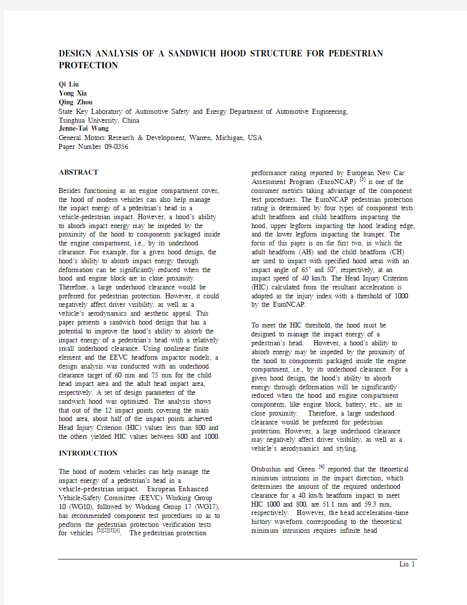
Otubushin and Green [6] reported that the theoretical minimum intrusions in the impact direction, which determines the amount of the required underhood clearance for a 40 km/h headform impact to meet HIC 1000 and 800, are 51.1 mm and 59.3 mm, respectively. However, the head acceleration-time history waveform corresponding to the theoretical minimum intrusions requires infinite head
acceleration at time zero as implied by Figure 1,
which is practically impossible to achieve.
Figure 1. Ideal acceleration waveform for the theoretical minimum intrusion [6].
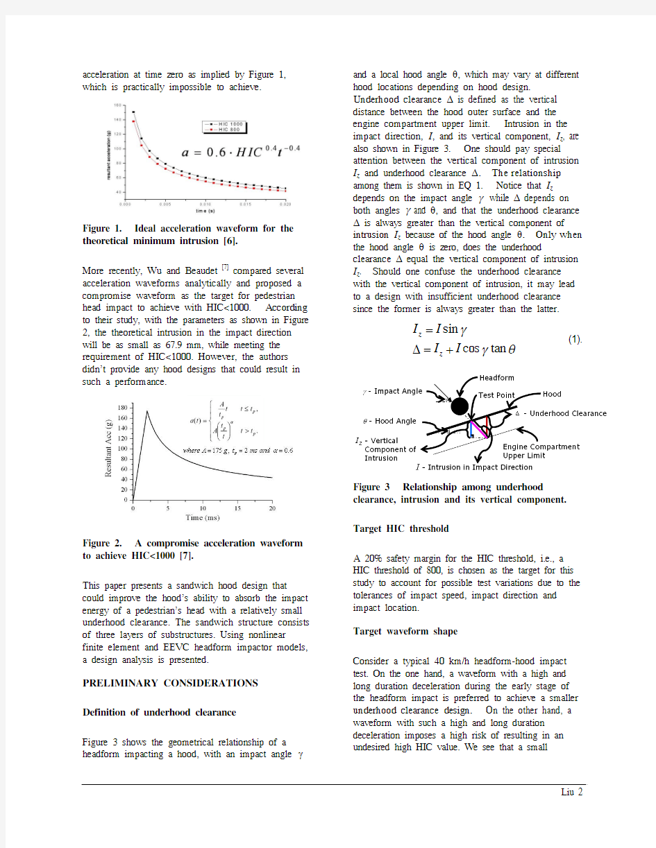
More recently, Wu and Beaudet [7] compared several
acceleration waveforms analytically and proposed a
compromise waveform as the target for pedestrian
head impact to achieve with HIC<1000. According
to their study, with the parameters as shown in Figure 2, the theoretical intrusion in the impact direction
will be as small as 67.9 mm, while meeting the
requirement of HIC<1000. However, the authors
didn’t provide any hood designs that could result in
such a performance.
Figure 2. A compromise acceleration waveform to achieve HIC<1000 [7].
This paper presents a sandwich hood design that could improve the hood’s ability to absorb the impact energy of a pedestrian’s head with a relatively small underhood clearance. The sandwich structure consists of three layers of substructures. Using nonlinear finite element and EEVC headform impactor models, a design analysis is presented.
PRELIMINARY CONSIDERATIONS Definition of underhood clearance
Figure 3 shows the geometrical relationship of a headform impacting a hood, with an impact angle γand a local hood angle θ, which may vary at different
hood locations depending on hood design.
Underhood clearance Δ is defined as the vertical
distance between the hood outer surface and the
engine compartment upper limit. Intrusion in the impact direction, I, and its vertical component, I z, are
also shown in Figure 3. One should pay special
attention between the vertical component of intrusion
I z and underhood clearance Δ. The relationship
among them is shown in EQ 1. Notice that I z
depends on the impact angle γ while Δ depends on both angles γ and θ, and that the underhood clearance Δ is always greater than the vertical component of intrusion I z because of the hood angle θ. Only when the hood angle θ is zero, does the underhood clearance Δ equal the vertical component of intrusion I z. Should one confuse the underhood clearance with the vertical component of intrusion, it may lead to a design with insufficient underhood clearance since the former is always greater than the latter.
sin
cos tan
z
z
I I
I I
γ
γθ
=
Δ=+
(1).
Figure 3 Relationship among underhood clearance, intrusion and its vertical component.
Target HIC threshold
A 20% safety margin for the HIC threshold, i.e., a HIC threshold of 800, is chosen as the target for this study to account for possible test variations due to the tolerances of impact speed, impact direction and impact location.
Target waveform shape
Consider a typical 40 km/h headform-hood impact test. On the one hand, a waveform with a high and long duration deceleration during the early stage of the headform impact is preferred to achieve a smaller underhood clearance design. On the other hand, a waveform with such a high and long duration deceleration imposes a high risk of resulting in an undesired high HIC value. We see that a small
underhood clearance and a low HIC value are two
competing performance requirements. Therefore, in
order to balance these competing performance
requirements an ideal headform deceleration pulse
should have a waveform with a sudden increase peaking at an appropriate level followed by a quick
decrease during the early stage of the impact.
Figure 4 depicts such a balanced waveform, which
offers an excellent HIC performance of 800 and a 68
mm intrusion in the impact direction. This waveform
is generated using a design tool, called the Dual
Asymmetrical Triangle Pulse Generator [8]. We use
it as the target waveform for our sandwich hood
structure.
Figure 4. Target waveform using the Dual Asymmetrical Triangle Pulse Generator [8]. MODEL DESCRIPTION
Sandwich hood
A late model mid-sized car, not designed to meet any pedestrian protection requirements, is selected as the study vehicle for the development of the sandwich hood structure. A finite element (FE) model of the sandwich hood, together with other necessary
front-end structures and components of the study
vehicle, was developed.
Figure 5 shows the exploded view of the sandwich
design and Figure 6 shows a sectional view of the
sandwich hood. The sandwich hood design consists
of three aluminum substructures: the outer hood as an
upper layer, the ripple plate as a middle layer, and the
support plate as a lower layer. The ripple plate has
two sections: the core ripple section in the central
area of the hood and the boarder section, in which the
ripple gradually diminishes toward the edge of the hood. The support plate is divided into two sections corresponding to CH and AH impact areas, namely CH section and AH section. The outer hood is bonded to the ripple plate with glue strips spread on the upper ridges of the main section of the ripple plate and glue spots in the outlier section of the ripple plate, as illustrated in Figure 7. The support plate is
bonded to the ripple plate with “finite rigid links”
(e.g., bolts, rivets or spotwelds), as shown in Figure
8.
Figure 5. Exploded view of the sandwich design for main hood area with color coded labels (upside-down view of the hood assembly).
Figure 6. Enlarged sectional view of sandwich hood assembly.
A design optimization analysis of the sandwich hood
structure was performed using nonlinear finite
element models. The final geometry parameters and material parameters of an optimized sandwich hood
are shown in Table 1 and Table 2. The total mass of
this sandwich hood design is 11.8 kg, about 27%
more than that of the original hood of the study
vehicle.
Figure 7. Glue distribution between the ripple plate and the outer hood (top view).
Figure 8 Rigid link distribution between the support plate and the ripple plate (bottom view).
Table 1.
Optimized geometry design parameters of the
sandwich hood assembly (unit: mm)
Component Dimension Outer hood thickness 1.05 Support plate thickness: CH / AH
1.2 / 1.8 Ripple plate thickness 0.5 Ripple upper ridge width 8 Ripple lower ridge width
20 Ripple height 6 Ripple interval
70
Table 2.
Material parameters of the sandwich hood
assembly M aterial model Density (kg/mm 3) Modulus (GPa) Yielding
strength
(MPa)
support
*MAT_024 2.6e-6 70 200
Glue *MAT_001 1.27e-6 0.03 /
Other components in the FE model
Besides the hood assembly, the FE model also includes other components shown in Figure 9 near the hood assembly that may be engaged in pedestrian head impacts, including the fenders, the front panel, the bumper stops, the towers, and the cowls, etc. These components constitute a more complete environment for pedestrian head impacts. The
lower part of the fenders, the towers and the cowls are all fixed to the vehicle reference frame in the model to provide the necessary boundary condition as shown in Figure 9. The hood assembly is constrained at the latch and hinge positions as a
conventional hood as shown in Figure 10. Specifically, the outer hood is fixed at the latch position and the ripple plate is rigidly linked to the original hinges in the model.
Figure 9. The FE model (hood assembly and underhood rigid wall excluded).
Figure 10. The hood assembly constraints at the latch and the two hinge positions.
Impact area definition
The wrap around distance (W AD) 1500 mm line [5] of the study vehicle is very close to the hood rear edge and leaves a rather small AH impact area as shown in Figure 11. To provide adequate AH impact area for
the purpose of this study, we artificially reduce the CH area and increase the AH area as shown in Figure 12. A base point (x=0 or xbase) is set at
W AD=1400 mm. Line x=0 separates CH area and AH area. Three impact points for AH and nine impact points for CH are selected as marked in Figure 13.
Figure 11. Baseline hood CH area definition according to EuroNCAP.
Figure 12. CH and AH area definition for analyses in this study.
Figure 13. CH and AH impact cases in the main hood area.
Target underhood clearance
An underhood clearance target of 60 mm and 75 mm
is selected for the CH area and the AH area,
respectively, as shown Figure 14 and Table 3. A
rigid wall of the same curvature as the outer hood at the specified vertical distance beneath the outer hood
is used in the FE model to represent underhood
components, such as an engine block.
Figure 14. Underhood clearance set for different impact areas.
Table 3.
Underhood clearance required for HIC<800
Headform requirement
Underhood
clearance
(mm)
CH 2.5 kg, 40 km/h, HIC<80060
AH 4.8 kg, 40 km/h, HIC<80075 SIMULATION RESULTS AND DISCUSSIONS
The results of all the 12 impact cases are summarized
in Table 4. As shown, HIC<1000 has been achieved
for all the impact points. Of these, all five impact
points along the centerline of the hood achieve
HIC<800. For the impact points away from the centerline of the hood, the HIC value becomes higher.
Rigid wall contact is observed from simulations at all
the four “ycenter” points and four “y+200” points.
No rigid wall contact occurs in any of the four
“y+400” cases. This means that at these “y+400”
impact points, the given underhood clearance is not
fully utilized, which implies that there is room for
further improvement for these impact points.
Table 4.
Simulation results
Area
Underhood
clearance
(mm)
Impact
point
HIC
y+400 y+200 ycenter AH 75 x+200
841
703*
764* CH 60
xbase 973 872* 751*
x-100 889 817* 776*
x-200 934 874* 788*
* Contacted with the underhood rigid wall.
Impact results in the CH area
Taking the three cases of “CH x-100” in Figure 15 as example, “CH x-100ycenter” and “CH x-100y+200”
cases have similar resultant acceleration waveform shapes. The latter has a higher first peak, probably
due to the effect of discontinuity of the scattered
lower links, while the former has the biggest
intrusion (represented by the Z_distance in Figure 15 (b)). “CH x-100y+400” case has a similar first peak
to that in “CH x-100ycenter” case.
(a)
(b)
Figure 15. Simulation results of “CH x-100” impact points.
Impact results in the AH area
The simulation results of AH at “x+200” points where the underhood clearance is set as 75 mm are shown in Figure 16. All the three cases achieve HIC below 900. Note that the first acceleration peaks for the three AH cases are lower than those of CH cases in the last sub-section. Actually, without considering CH, the hood can be optimized for AH to reach less underhood clearance required for HIC 800. However, such optimized hood will be too strong and may have too much active mass for CH impact,
causing high first peak of acceleration and generating HIC greater than 800. Therefore, the hood must be designed somewhat softer for satisfying CH impact, and yet the softened hood needs larger underhood clearance for AH impact.
(a)
(b)
Figure 16. Simulation results of “AH x+200” impact positions.
SUMMARY
A sandwich hood structure is proposed for improving the hood’s ability to absorb the impact energy of a pedestrian’s head with a relatively small underhood clearance. A design optimization analysis for the sandwich hood structure is performed using a study vehicle and FE models. The total mass of this
optimized sandwich hood design is about 27% more than that of the original hood of the study vehicle. An underhood clearance of 60 mm and 75 mm is achieved for the child headform impact area and the adult headform impact area, respectively. Of the 12 impact positions covering the main hood area, about half of the impact points meet the HIC<800 and the others achieve HIC from 800 to 1000. However, no attempt was made to assess manufacturability of the sandwich structure in this study. Further
developments to address all safety requirements, including performance in real-world crash events, are also necessary before implementing this feature in a production vehicle.
REFERENCES
[1]European Enhanced Vehicle Safety Committee
(EEVC) Working Group 17. Improved test
methods to evaluate pedestrian protection
afforded by passenger cars (December 1998 with September 2002 updates), 2003,
https://www.360docs.net/doc/dd16484971.html,/publicdocs/publicdocs.htm. [2]The European Parliament and the Council of the
European Union, Directive 2003/102/EC,
Official Journal of the European Union, L 321:
15-25.
[3]Commission of the European communities.
Proposal for a Regulation of the European
Parliament and of the Council on the protection
of pedestrians and other vulnerable road users.
2007,
http://ec.europa.eu/enterprise/automotive/pagesb
ackground/pedestrianprotection/index.htm. [4]Commission of the European communities.
Commission working document on the measures necessary to implement the proposed regulation
on pedestrian protection. 2008,
http://ec.europa.eu/enterprise/automotive/pagesb
ackground/pedestrianprotection/index.htm. [5]European New Car Assessment Programme
(EuroNCAP) Assessment Protocal and
Biomechanical Limites, Version 3, April 2001.
[6]Otubushin, A. and Green, J., “An Analytical
Assessment of Pedestrian Head Impact
Protection,” Proceedings of The 16th
International Technical Conference on the
Enhanced Safety of Vehicles (ESV), Windsor,
Ontario, Canada, May 31 - June 4, 1998.
[7]Wu, J. P. and Beaudet, B., “Optimization of head
impact waveform to minimize HIC,” SAE Paper No. 2007-01-0759.
[8]Cheng, C.-S. and Wang, J. T., “An Analytical
Study of Pedestrian Headform Impacts Using a
Dual Asymmetrical Triangle Function,” GM
R&D Publication No. R&D-9326, May 2002;
Conference Proceedings of Crashworthiness,
Occupant Protection and Biomechanics in
Transportation Systems, the 2002 ASME
International Congress, New Orleans, La.