BXCD4545_revG BXCD4545 Datasheet
BRIDGELUX BLUE POWER DIE
BXCD 45 mil x 45 mil
PRODUCT DATA SHEET DS-C15
The Bridgelux family of blue power die enables high performance and cost effective solutions to serve solid state lighting market. This next generation chip technology delivers improved efficiency and performance to enable increased light output for a variety of lighting, signaling and display applications.
Features
?High lumen output and efficiency
?Long operating life
?100% Tested and sorted by wavelength, power and forward voltage
?Lambertian emission pattern
?Compatible with Solder paste, solder preform or silver epoxy die attach
?Delivered on medium tack blue tape (20cm±10mm ×20 cm±10mm) Applications
?General Illumination
?Portable Lighting
?Architectural Lighting
?Directional Lighting
?Display Backlighting
?Digital Camera Flash
?Automotive Lighting
?White LEDs
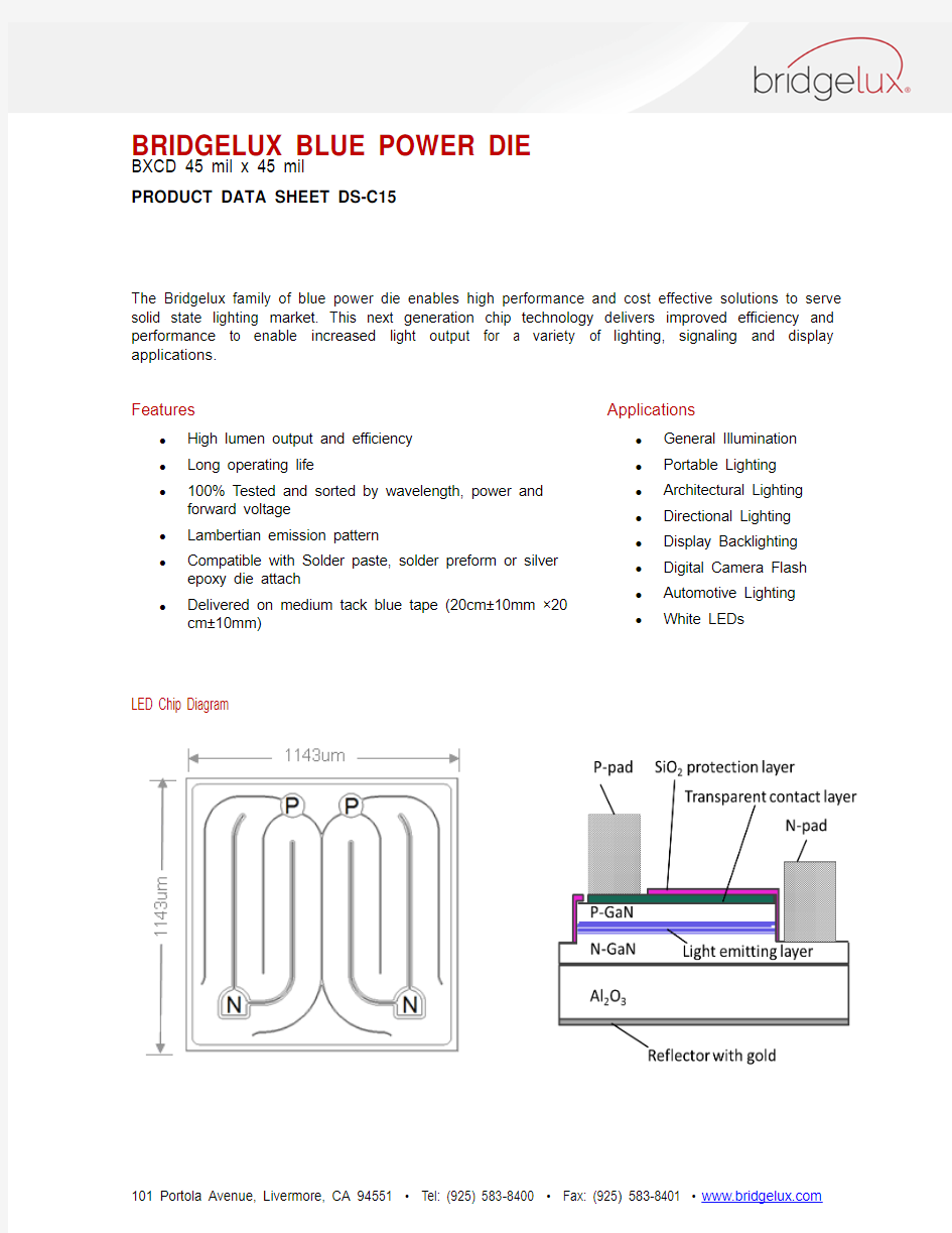
LED Chip Diagram
BRIDGELUX BLUE POWER DIE
BXCD 45 mil x 45 mil
Product Nomenclature
B X
C
D 4545 X X X – Y – Z
Where:
BXCD: Designates product family
4545: Designates die size (45 mil x 45 mil)
XXX: Designates dominant wavelength bin
Y: Designates radiometric power bin
Z: Designates forward voltage bin
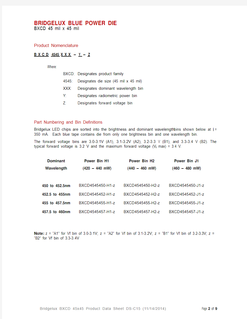
Part Numbering and Bin Definitions
Bridgelux LED chips are sorted into the brightness and dominant wavelength bins shown below at I f = 350 mA. Each blue tape contains die from only one brightness bin and one wavelength bin.
The forward voltage bins are 3.0-3.1V (A1), 3.1-3.2V (A2), 3.2-3.3 V (B1), and 3.3-3.4 V (B2). The typical forward voltage is 3.2 V and the maximum forward voltage (V f max) = 3.4 V.
Dominant Wavelength
Power Bin H1
(420 – 440 mW)
Power Bin H2
(440 – 460 mW)
Power Bin J1
(460 – 480 mW)
450 to 452.5nm BXCD4545450-H1-z BXCD4545450-H2-z BXCD4545450-J1-z 452.5 to 455nm BXCD4545452-H1-z BXCD4545452-H2-z BXCD4545452-J1-z 455 to 457.5nm BXCD4545455-H1-z BXCD4545455-H2-z BXCD4545455-J1-z 457.5 to 460nm BXCD4545457-H1-z BXCD4545457-H2-z BXCD4545457-J1-z
Note:z = “A1” for Vf bin of 3.0-3.1V; z = “A2” for Vf bin of 3.1-3.2V; z = “B1” for Vf bin of 3.2-3.3V; z = “B2” for Vf bin of 3.3-3.4V
BRIDGELUX Blue Power Die
BXCD 45 mil x 45 mil
Mechanical Dimensions
Absolute Maximum Ratings
Notes:
1. Maximum drive current depends on junction temperature, die attach methods/materials, and lifetime
requirements of the application.
2. Bridgelux LED chips are Class 1 ESD sensitive.
3. The typical spectra half-width of the BXCD4545 blue power die is < 25 nm.
4. Please consult the Bridgelux technical support team for information on how to optimize the light output of
our chips in your package.
5. Brightness values are measured in an integrating sphere using gold plated TO39 headers without
encapsulation.
6. Tapes should be stored in a vertical orientation, not horizontally stacked. Stacking of tapes can place
excessive pressure on the bond pads of the LED, resulting in reduced wire bonding strength.
BRIDGELUX BLUE POWER DIE
BXCD 45 mil x 45 mil
Environmental Compliance
Bridgelux is committed to providing environmentally friendly products to the solid state lighting market. Bridgelux BXCD4545 blue power die are compliant to the European Union directives on the restriction of hazardous substances in electronic equipment, namely the RoHS directive. Bridgelux will not intentionally add the following restricted materials to BXCD4545 die products: lead, mercury, cadmium, hexavalent chromium, polybrominated biphenyls (PBB) or polybrominated diphenyl ethers (PBDE).
Performance vs. Current
The following curves represent typical performance of the BXCD4545 blue power die. Actual performance will vary slightly for different power, dominant wavelength and Vf bins.
Figure 1: Relative Luminous Intensity vs. Forward Current (T j = 25°C)
Figure 2: Forward Current vs. Forward Voltage (T j = 25°C)
Performance vs. Junction Temperature
The following curves represent typical performance of the BXCD4545 blue power die. Actual performance will vary slightly for different power, dominant wavelength and Vf bins.
Figure 3: Forward Voltage Shift vs. Junction Temperature
Figure 4: Relative Light Intensity vs. Junction Temperature
Wavelength Shift
The following curves represent typical performance of the BXCD4545 blue power die. Actual performance will vary slightly for different power, dominant wavelength and Vf bins.
Figure 5: Wavelength Shift vs. Junction Temperature
Typical Radiation Pattern
Figure 7: Typical Radiation Pattern (350 mA Operation)
Current De-rating Curves
Figure 8: Current Derating Curve vs. Ambient Temperature (derating based on T j max 150°C)
About Bridgelux
Bridgelux is a leading developer and manufacturer of technologies and solutions transforming the $40 billion global lighting industry into a $100 billion market opportunity. Based in Livermore, California, Bridgelux is a pioneer in solid state lighting (SSL), expanding the market for light emitting diode (LED) technologies by driving down the cost of LED lighting systems. Bridgelux’s patented light source technology replaces traditional technologies (such as incandescent, halogen, fluorescent and high intensity discharge lighting) with integrated, solid state lighting solutions that enable lamp and luminaire manufacturers to provide high performance and energy-efficient white light for the rapidly growing interior and exterior lighting markets, including street lights, commercial lighting and consumer applications. Bridgelux is the only vertically integrated LED manufacturer and developer of solid-state light sources that designs its solutions specifically for the lighting industry.
For more information about the company, please visit https://www.360docs.net/doc/e517013296.html,
? 2014 Bridgelux, Inc. All rights reserved. Product specifications are subject to change without notice.