PPM-Encoder-V3-Manual

PPM encoder module Translates up to eight PWM (pulse width modulation) signals into one PPM (pulse position modulation) signal, allowing you to connect a PWM receiver to a PPM-compatible autopilot over one wire
Three-wire cable (12 cm)DF13 three-position to servo cable connects the encoder to the autopilot
Ten-wire cable (7 cm)DF13 ten-position to servo cable connects
the PWM receiver to the encoder
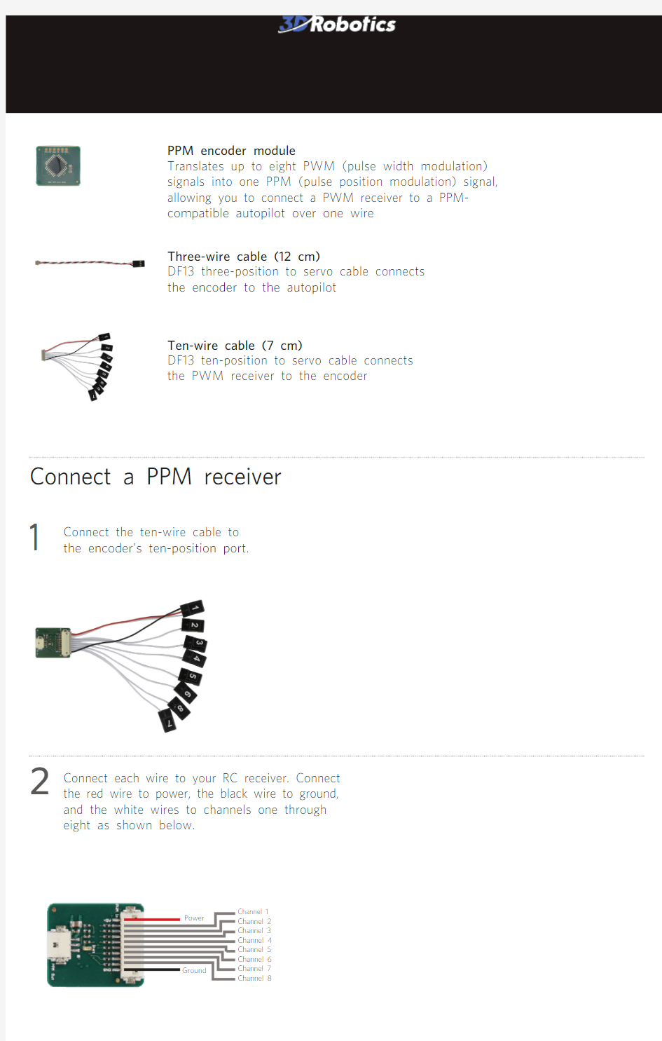
Connect the ten-wire cable to the encoder’s ten-position port.
Connect each wire to your RC receiver. Connect the red wire to power, the black wire to ground, and the white wires to channels one through
eight as shown below.Channel 1Channel 2Channel 3Channel 4Channel 5Channel 6Channel 7
Channel 8
Power
Ground PPM ENCODER
Connect a PPM receiver
12
signal (s) white wire power (+) red wire ground (-) black wire
Connect a PPM jumper (included with APM) to signal pins 2 and 3. Connect three-wire
cable to ground, power, and signal pins 1.
PPM jumper
Pixhawk ground (-) black wire power (+) red wire signal (s) white wire
Connect to RC pins.
Connect to signal, power,
and ground input pins 1.
signal (s) white wire power (+) red wire ground (-) black wire
Connect the three-wire cable to your autopilot’s input pins.4PX4
APM 2.6
Connect the three-wire cable to the encoder’s three-position port.
3
For customer support, contact us at help@https://www.360docs.net/doc/fa5997050.html,
or call our support line at +1 (858) 225-1414
Monday through Friday, from 8 am to 5 pm, PST.
PPM Encoder User Manual V1 | ?3D Robotics, Inc. | 13 January 2014Support
Specifications
? ATmega328p microcontroller, firmware upgrade enabled through AVRISP programmer ? 22 x 19 x 5.5 mm (without cables)? 1.45 g
Failsafe configuration
Failsafes can protect your vehicle from loss of radio signal.
To learn more about configuring failsafes with your PPM encoder, visit the APM Wiki page here .
Configuration
No configuration is necessary to use the PPM encoder out of the box, just connect and power to translate PWM into PPM over one wire. For information on reloading firmware onto the encoder, visit the APM Wiki page here .
The ATmega328p firmware can be downloaded here for planes and rovers and here for copters .
LED When powered, the LED indicates the status of the radio signal.
Slow to fast blinking blue: signal in good health, speed corresponds to throttle channel position
Very fast to constant blue: throttle channel lost or all channels lost